W ADCINC
Bạn đang xem bản rút gọn của tài liệu. Xem và tải ngay bản đầy đủ của tài liệu tại đây (228.03 KB, 18 trang )
4. Incremental ADC
Incremental ADC
ADCINC v1.0
Copyright © 2002-2003. Cypress MicroSystems Inc. All Rights Reserved.
CY8C29/27/24/22xxx Data Sheet
PSoC™ Blocks
Resources
Digital
Analog CT
API Memory (Bytes)
Analog SC
Flash
RAM
Pins (per
External I/O)
CY8C29/27/24/22xxx
1st Order Modulator
1
1
8
1
2nd Order Modulator
1
2
8
1
Features and Overview
• 6 to 14-bit resolution
• Synchronous 8-bit PWM Output
• Optional Differential Input
• Singned or Unsigned data format
• Sample rate up to 46.8ksps (6-bit resolution)
• Input range defined by internal and external reference options
• Internal or external clock
The ADCINC User Module implements an Incremental A/D with a selectable range of 6 to 14 bits and
signed or unsigned data formats. Input voltage ranges, including rail-to-rail, may be measured by
configuring the proper reference voltage and analog ground. The output is based on an input voltage
between -Vref and +Vref centered at AGND. The ADCINC programming interface allows the user to select
from 0 to 255 samples, where zero specifies continuous sampling.
Timing is implemented with an eight bit PWM giving the User a modulated pulse width that is sychrounous
to the input sample.
The ADCINC requres 2n iintegration cycles to generate a output with n bits of resoltion. Parameters
section prior to module placement.
Input
Decimator
System Bus
PWM
1:4
4
Row Bus
Data Clock
ADCINC Block Diagram
September 7, 2004
1
User Module Data Sheet
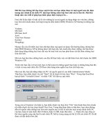
Functional Description
The ADCINC provides a first-order modulator formed from a single analog switched capacitor PSoC block,
one digital PSoC block, and the decimator, as shown in the following figure.
SC PSoC Block
φ1
FCAP
= 32
φ1*Reset
ACAP
= 16
φ1
Vin
φ2
Data Bus
Data
φ2
Ref +
Decimator
Ref -
Data
Latch
Analog Column Comparator Bus
÷4
Analog
Column Clock
φ1,φ2
CPU
Interrupt
φ1
φ2
8-Bit
PWM
Generator
Source
Clock
Row Bus
Schematic of the ADCINC with First-Order Modulator
SC PSoC Block
FCAP
= 32
Vin
Ref +
φ1
ACAP
=8
SC PSoC Block
φ1
φ2
φ1*Reset
φ1
ACAP
= 16
φ1
φ2
φ1*Reset
Data
Bus
Data
φ2
Ref +
Ref -
Ref -
Analog
Column Clock
Source
Clock
FCAP
= 32
÷4
φ1,φ2
φ1
φ2
Generator
φ2
Decimator
Analog Column Comparator Bus
Data
Latch
8-Bit
PWM
CPU
Interrupt
Row Bus
Schematic of the ADCINC with Second-Order Modulator
The range of the ADCINC is set at ±VRef, where VRef is set by the user in the Global Resources window of
PSoC Designer. For fixed scale, VRef is set to ±VBandgap ,, ±1.6 VBandgap. For adjustable scale, VRef is set
to ±Port 2[6]. For supply ratiometric scale, VRef is set to ±VDD/2.
The analog block is configured as a resettable integrator. Depending on the output polarity, the reference
control is configured so that the reference voltage is either added or subtracted from the input and placed
in the integrator. This reference control attempts to pull the integrator output back towards AGND. If the
integrator is operated 2Bits) times and the output voltage comparator is positive "n" of those times, the
residual voltage (Vresid) at the output is:
2
September 7, 2004
Incremental ADC
V resid = 2
Bits
⋅ V in – n ⋅ V ref + ( 2
Bits
– n ) ⋅ V ref
Equation 1
Bits – 1
V resid
n–2
- V ref + ------------V in = ------------------------Bits – 1
Bits
2
2
Equation 2
This equation states that the range of this ADC is +/- VRef, the resolution (LSB) is VRef/2Bits-1, and the
voltage on the output at the end of the computation is defined as the residue. Since Vresid is always less
than VRef, Vresid/2Bits less than half a LSB and can be ignored.
To make the integrator function as an incremental ADC, the following digital resources are utilized:
•
•
A PWM to count the proper number of integration cycles.
A decimator, configured in the incremental mode, to accumulate the number of cycles that the output
comparator is positive.
CAUTION When placing this module, it is imperative that it is configured with the same source clock for
both the analog and digital blocks. Failure to do so will cause it to operate incorrectly.
The PWM is set up to generate an interrupt every 256 counts or 64 integration cycles. This defines one
integrate cycle. The decimator counter is set up to accumulate 2Bits/64 of these time cycles. The
accumulated value is sampled at the start and finish of the integrate time. A single cycles is added to reset
the integrator and process the answer.
PWM Output
Reset
Integrator
Timer Cycles
PWM Interrupts
R
1
2
3
Read Decimator Count
(d0)
4
5
6
2#bits-6-1 2#bits-6
R
1
2
3
Read Decimator Count (d1)
Process ADC Value(d1-d0)
Timing for ADCINC
Immediately at the start of timer cycle #1, the decimator value is read and stored. At the start of the reset
cycle the decimator value is read again. These difference of these two values are used to calculate the
answer.. Also during rest the integrator is reset to remove any accumulated residue.The flag variable is set
signifying that new data is available.
Because the ACDINC control is interrupt based and the sample time is relatively long, it is unreasonable to
expect the processor to wait while a sample is being processed. The primary communication between the
ADC routine and the main program is a data-available flag that may be polled. APIs are available to check
the data flag and retrieve data.
The data handler was designed to be poll based. If an interrupt-based data handler is desired, applicationspecific data handler code can be added to the interrupt routine _ADCINC_ADConversion_ISR, located in
the assembly file ANDINCINT.asm. The point to insert code is clearly marked.
September 7, 2004
3
User Module Data Sheet
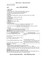
The frequency domain magnitude plot below normalizes the frequency so the 14-bit sampe rate, Fnom =
1.0. The -3 dB point occurs at .443 ∞ Fnom and zeros of the function occur at each integer multiple of FS.
Since the ADCINCPWM is fset for a resolution of 14 bits, actually samples 16385 times faster than the
nominal output rate, the Nyquist limit is 8,192 higher, 13 octaves above Fnom, which significantly reduces
the reqirements for an anti-alias filter. The Nyquist limit is 12 octives for 13 bits of resolution, 11 octives for
12 bits of resolution, and so on.
.
0
-10
-20
-30
-40
-50
-60
-70
-80
-90
0.01
0.1
1
10
100
1000
10000
Frequency Domain Magnitude Plot
DC and AC Electrical Characteristics
CY8C29/27/24/22xxx Preliminary Specifications
The following values are indicative of expected performance and based on initial characterization data.
Unless otherwise specified below TA = 25°C, Vdd = 5.0V, Power HIGH, Op-Amp bias LOW, output
referenced to 2.5V external Analog Ground on P2[4] with 1.25 external Vref on P2[6].
2nd-Order Modulator DC and AC 5.0V Electrical Characteristics
Parameter
Typical
Limit
Units
---
Vss to Vdd
V
3
---
pF
1/(C*clk)
---
Ω
Resolution
---
8
Bits
Sample Rate
---
.125 to 31.25
ksps
SNR
46
---
dB
Conditions and Notes
Input
Input Voltage Range
Input
Capacitance1
Input Impedance
Ref Mux = Vdd/2 ± Vdd/2
DC Accuracy
4
September 7, 2004
Incremental ADC
2nd-Order Modulator DC and AC 5.0V Electrical Characteristics
Parameter
Typical
Limit
Units
DNL
0.1
---
LSB
INL
0.5
---
LSB
Offset Error
10
---
mV
Including Reference Gain Error
3.0
--
% FSR
Excluding Reference Gain Error2
0.1
--
% FSR
Low Power
180
---
uA
Med Power
840
---
uA
High Power
3450
---
uA
---
0.032 to 8.0
MHz
Conditions and Notes
Column Clock 2 MHz
Gain Error
Operating Current
Data Clock
Input to digital blocks and analog column clock
1st-Order Modulator DC and AC 5.0V Electrical Characteristics, CY8C29/27/24/22xxxFamily of PSoC Devices
Parameter
Typical
Limit
Units
Input Voltage Range
---
Vss to Vdd
Input Capacitance1
3
---
pF
1/(C*clk)
---
Ω
Conditions and Notes
Input
Input Impedance
Ref Mux = Vdd/2 ± Vdd/2
Resolution
---
8
Bits
Sample Rate
---
.125 to 31.25
ksps
SNR
44
---
dB
DNL
0.6
---
LSB
INL
0.7
---
LSB
5
---
mV
3.0
--
% FSR
0.1
--
% FSR
Low Power
50
---
uA
Med Power
500
---
uA
High Power
1900
---
uA
---
0.032 to 8.0
MHz
DC Accuracy
Offset Error
Column Clock 2 MHz
Gain Error
Including Reference Gain Error
Excluding Reference Gain
Error2
Operating Current
Data Clock
September 7, 2004
Input to digital blocks and analog column clock
5
User Module Data Sheet
The following values are indicative of expected performance and based on initial characterization data.
Unless otherwise specified below, TA = 25°C, Vdd = 3.3V, Power HIGH, Op-Amp bias LOW, output
referenced to 1.64V external Analog Ground on P2[4] with 1.25 external Vref on P2[6].
2nd-Order Modulator DC and AC 3.3V Electrical Characteristics, CY8C29/27/24/22xxx Family of PSoC
Devices
Parameter
Typical
Limit
Units
Input Voltage Range
---
Vss to Vdd
V
Input Capacitance1
3
---
pF
1/(C*clk)
---
Ω
Resolution
---
8
Bits
Sample Rate
---
.125 to 31.25
ksps
SNR
46
---
dB
DNL
0.1
---
LSB
INL
0.5
---
LSB
Offset Error
10
---
mV
3.0
--
% FSR
0.3
--
% FSR
Low Power
130
---
uA
Med Power
840
---
uA
High Power
3370
---
uA
---
0.032 to 8.0
MHz
Conditions and Notes
Input
Input Impedance
Ref Mux = Vdd/2 ± Vdd/2
DC Accuracy
Column Clock 2 MHz
Gain Error
Including Reference Gain Error
Excluding Reference Gain
Error2
Operating Current
Data Clock
Input to digital blocks and analog column clock
1st-Order Modulator DC and AC 3.3V Electrical Characteristics, CY8C29/27/24/22xxx Family of PSoC Devices
Parameter
Typical
Limit
Units
Input Voltage Range
---
Vss to Vdd
V
Input Capacitance1
3
---
pF
1/(C*clk)
---
Ω
Resolution
---
8
Bits
Sample Rate
---
.125 to 31.25
ksps
SNR
44
---
dB
DNL
0.6
---
LSB
INL
0.8
---
LSB
6
---
mV
Conditions and Notes
Input
Input Impedance
Ref Mux = Vdd/2 ± Vdd/2
DC Accuracy
Offset Error
6
Column Clock 2 MHz
September 7, 2004
Incremental ADC
1st-Order Modulator DC and AC 3.3V Electrical Characteristics, CY8C29/27/24/22xxx Family of PSoC Devices
Parameter
Typical
Limit
Units
Including Reference Gain Error
3.0
--
% FSR
Excluding Reference Gain Error2
0.3
--
% FSR
Low Power
50
---
uA
Med Power
500
---
uA
High Power
1900
---
uA
---
0.032 to 8.0
MHz
Conditions and Notes
Gain Error
Operating Current
Data Clock
Input to digital blocks and analog column clock
Electrical Characteristics Notes
1. Includes I/O pin.
2. Reference Gain Error measured by comparing the external reference to VRefHigh and VRefLow routed through the
test mux and back out to a pin.
Placement
The first-order modulator design requires two PSoC blocks, one digital and one analog. No inherent
limitations govern placement of the analog block; the only considerations are input and clock availability.
The digital block, however, must be able to feed the hardware decimator. In the CY8C27xxx family the
qualified digital blocks are DBB01, DBB02, DDB05 and DCB06. In the CY8C29/24/22xxx device families
any of the digital blocks can be used. As noted later, both blocks must utilize the same source clock.
Placement for second-order modulator design differs from the first-order design in that there is a second
switched capacitor PSoC block. Both analog blocks must lie in the same column so they can share the
column comparator bus. The digital block is subject to the same restrictions for both first- and secondorder modulators.
Although there are a number of placements possible for the analog and digital blocks, the ADCINC also
utilizes the PSoC device’s only hardware decimator. Only one ADCINC instance may be placed for a given
configuration. With dynamic re-configuration it is possible to load more than one configuration as long as
the blocks do not overlap. Though both instances will appear to work, only the output of the one most
recently loaded would be correct.
Parameters and Resources
Once a ADCINPWM instance is placed, nine parameters must be configured for proper operation: the
Resolution, DataFormat, DataClock, PosInput Signal Multiplexer selection, NegInput Multipler selection,
NegInput gain, Clock Pase, Pulse Width, and PWM Output
Resolution
Valid resolution options are from 6 to 14 bits.
DataFormat
May be selected to be signed or unsigned format.
September 7, 2004
7
User Module Data Sheet
Data Clock
The Data Clock determines the sample rate. This clock goes to both PSoC blocks of the first-order
modulator design and to all three PSoC block of the second-order design.
CAUTION It is imperative that the same clock is selected for both the digital block and the analog column clock or this user module will not function correctly.
The Data Clock should not be set to less than 250 kHz when the CPU is running at 24 MHz. Otherwise, it
may be set as low as 125 kHz. The Data Clock may not exceed the CPU clock, it must always be equal to
or less than CPU Clock. The PWM is set to provide an interrupt every 256 counts of the Data Clock.The
counter integrates the signal for 2Bits-6 of these cycles. An additional cycle is required to reset the
integrator and process the data. The sample rate is defined as follows.
DataClock SampleRate = --------------------------------------Bits – 6
256 ⋅ 2
+1
Equation 3
The maximum DataClock that can be used is 8MHz. This is due to limitations of the Swtiched Cap blocks.
The maximum sample rate for each of the various bit rates can be calculated using an 8MHz clock rate
and are illustrated in the table below.
Resolution
Maximum Sample Rate
6-bit
31.1ksps
7-bit
15.6ksps
8-bit
7.8ksps
9-bit
3.9ksps
10-bit
1.95ksps
11-bit
976sps
12-bit
488sps
13-bit
244sps
14-bit
122sps
The sample window determines the normal mode frequencies the ADC will reject. It is defined as follows.
Bits
2
SampleWindow = ---------------------------DataClock
Equation 4
To reject a higher frequency and its harmonics, select the sample window such that it is an even multiple
of the frequency-to-reject.
PosInput
The main input to the ADC. PSoC Designer allows the user to select any legal input.
NegInput
Allows for the creation of a differential input for the ADC. This input can be weighted through the use of the
NegInput Gain parameter. If a single input as opposed to a differential input is desired then set the
8
September 7, 2004
Incremental ADC
NegInput Gain parameter value to “Disconnected”. For the NegInput parameter PSoC Designer allows the
user to select any legal input.
NegInput Gain
Allows different weighting value for the negative input. If single input is desired, set this value to
“Disconnected”
Clock Phase
The selection of the Clock Phase is used to synchronize the output of one analog PSoC block to the input
of another. The switched capacitor analog PSoC blocks use a two-phase clock (f1, f2) to acquire and
transfer signals. Normally, the input to the ADCINC is sampled on f1. A problem arises in that many of the
user modules auto-zero their output during f1 and only provide a valid output during f2. If such a module's
output is fed to the ADCINC’s input, it will acquire an auto-zeroed output instead of a valid signal. The
Clock Phase selection allows the phases to be swapped, so that the input signal is acquired during f2.
PulseWidth
Allows PWM pulsewidth to set from a value 1 to 255 counts. If no value is set then the User Module will
automatically set the PWM pulsewidth to 1 when the GetSamples function is called.
PWM output
The Output parameter may be disabled or routed to one of four global output signals.
Interrupt Generation Control
The following parameter is only accessible when the Enable Interrupt Generation Control check box in
PSoC Designer is checked. This is available under Project >> Settings... >> Device Editor.
IntDispatchMode
The IntDispatchMode parameter is used to specify how an interrupt request is handled for interrupts
shared by multiple user modules existing in the same block but in different overlays. Selecting
“ActiveStatus” causes firmware to test which overlay is active before servicing the shared interrupt
request. This test occurs every time the shared interrupt is requested. This adds latency and also
produces a nondeterministic procedure of servicing shared interrupt requests, but does not require any
RAM. Selecting “OffsetPreCalc” causes firmware to calculate the source of a shared interrupt request only
when an overlay is initially loaded. This calculation decreases interrupt latency and produces a
deterministic procedure for servicing shared interrupt requests, but at the expense of a byte of RAM.
Application Programming Interface
The Application Programming Interface (API) routines are provided as part of the user module to allow the
designer to deal with the module at a higher level. This section specifies the interface to each function
together with related constants provided by the “include” files.
Note
In this, as in all user module APIs, the values of the A and X register may be altered by calling an
API function. It is the responsibility of the calling function to preserve the values of A and X prior to
the call if those values are required after the call. This “registers are volatile” policy was selected
for efficiency reasons and has been in force since version 1.0 of PSoC Designer. The C compiler
automatically takes care of this requirement. Assembly language programmers must ensure their
code observes the policy, too. Though some user module API function may leave A and X
unchanged, there is no guarantee they will do so in the future.
September 7, 2004
9
User Module Data Sheet
Each time a user module is placed, it is assigned an instance name. By default, PSoC Designer assigns
the ADCINC_1 to the first instance of this user module in a given project. It can be changed to any unique
value that follows the syntactic rules for identifiers. The assigned instance name becomes the prefix of
every global function name, variable and constant symbol. In the following descriptions the instance name
has been shortened to ADCINC for simplicity.
ADCINC_Start
Description:
Performs all required initialization for this user module and sets the power level for the switched capacitor PSoC block. The PWM is started
C Prototype:
void ADCINC_Start (BYTE bPowerSetting)
Assembly:
mov
A, bPowerSetting
call ADCINC_Start
Parameters:
bPowerSetting: One byte that specifies the power level. Following reset and configuration, the analog
PSoC block assigned to ADCINC is powered down. Symbolic names provided in C and assembly, and
their associated values, are given in the following table.
Symbolic Name
Value
ADCINC_OFF
0
ADCINC_LOWPOWER
1
ADCINC_MEDPOWER
2
ADCINC_HIGHPOWER
3
Return Value:
None
Side Effects:
The A and X registers may be modified by this or future implementations of this function. The same is
true for all RAM page pointer registers in the Large Memory Model (CY8C29xxx). When necessary, it
is the calling function's responsibility to preserve the values across calls to fastcall16 functions.
ADCINC_SetPower
Description:
Sets the power level for the switched capacitor PSoC block.
C Prototype:
void ADCINC_SetPower (BYTE bPowerSetting)
Assembly:
mov
A, bPowerSetting
call ADCINC_SetPower
Parameters:
bPowerSetting: Same as the bPowerSetting parameter used for the Start entry point.
Return Value:
None
10
September 7, 2004
Incremental ADC
Side Effects:
The A and X registers may be modified by this or future implementations of this function. The same is
true for all RAM page pointer registers in the Large Memory Model (CY8C29xxx). When necessary, it
is the calling function's responsibility to preserve the values across calls to fastcall16 functions.
ADCINC_Stop
Description:
Sets the power level on the switched capacitor PSoC block to OFF.
C Prototype:
void ADCINC_Stop (void)
Assembly:
call ADCINC_Stop
Parameters:
None
Return Value:
None
Side Effects:
The A and X registers may be modified by this or future implementations of this function. The same is
true for all RAM page pointer registers in the Large Memory Model (CY8C29xxx). When necessary, it
is the calling function's responsibility to preserve the values across calls to fastcall16 functions.
ADCINC_GetSamples
Description:
Runs the ADC for the specified number of samples
C Prototype:
void ADCINC_GetSamples (BYTE bNumSamples)
Assembly:
mov
A, bNumSamples
call ADCINC_GetSamples
Parameters:
bNumSamples: 8-bit value that sets the number of samples to be converted. As a value of ‘0’ causes
the ADC to run continuously.
Return Value:
None
Side Effects:
The A and X registers may be modified by this or future implementations of this function. The same is
true for all RAM page pointer registers in the Large Memory Model (CY8C29xxx). When necessary, it
is the calling function's responsibility to preserve the values across calls to fastcall16 functions. Currently, only the CUR_PP page pointer register is modified.
ADCINC_StopADC
Description:
Immediately stops the ADC. PWM continues to run.
C Prototype:
void ADCINC_StopADC (void)
September 7, 2004
11
User Module Data Sheet
Assembly:
call ADCINC_StopADC
Parameters:
None
Return Value:
None
Side Effects:
The A and X registers may be modified by this or future implementations of this function. The same is
true for all RAM page pointer registers in the Large Memory Model (CY8C29xxx). When necessary, it
is the calling function's responsibility to preserve the values across calls to fastcall16 functions.
ADCINC_fIsDataAvailable
Description:
Checks the availability of sampled data.
C Prototype:
BYTE ADCINC_bfIsDataAvailable(void)
Assembly:
call ADCINC_bfIsDataAvailable
Parameters:
None
Return Value:
Returns a non-zero value if data has been converted and is ready to read.
Side Effects:
The A and X registers may be modified by this or future implementations of this function. The same is
true for all RAM page pointer registers in the Large Memory Model (CY8C29xxx). When necessary, it
is the calling function's responsibility to preserve the values across calls to fastcall16 functions. Currently, only the CUR_PP page pointer register is modified.
ADCINC_iGetData
Description:
Returns converted data as a signed integer. ADCINC_bfIsDataAvailable() should be called to verify
that the data sample is ready.
C Prototype:
INT
ADCINC_iGetData(void)
Assembly:
call ADCINC_iGetData
Parameters:
None
; Data will be in A and X upon return
Return Value:
Returns the converted data sample in 16-bit 2’s complement format.
Side Effects:
The A and X registers may be modified by this or future implementations of this function. The same is
true for all RAM page pointer registers in the Large Memory Model (CY8C29xxx). When necessary, it
is the calling function's responsibility to preserve the values across calls to fastcall16 functions. Currently, only the CUR_PP page pointer register is modified.
12
September 7, 2004
Incremental ADC
ADCINC_wGetData
Description:
Returns converted data as an unsigned integer. ADCINC_bfIsDataAvailable() should be called to verify that the data sample is ready.
C Prototype:
WORD ADCINC_wGetData(void)
Assembly:
call ADCINC_wGetData
Parameters:
None
; Data will be in A and X upon return
Return Value:
Returns the converted 16-bit unsigned data sample.
Side Effects:
The A and X registers may be modified by this or future implementations of this function. The same is
true for all RAM page pointer registers in the Large Memory Model (CY8C29xxx). When necessary, it
is the calling function's responsibility to preserve the values across calls to fastcall16 functions. Currently, only the CUR_PP page pointer register is modified.
ADCINC_cGetData
Description:
Returns converted data as a signed char. ADCINC_bfIsDataAvailable() should be called to verify that
the data sample is ready.
C Prototype:
CHAR ADCINC_cGetData(void)
Assembly:
call ADCINC_cGetData
Parameters:
None
; Data will be in A upon return
Return Value:
Returns the converted data sample in 8-bit 2’s complement format.
Side Effects:
The A and X registers may be modified by this or future implementations of this function. The same is
true for all RAM page pointer registers in the Large Memory Model (CY8C29xxx). When necessary, it
is the calling function's responsibility to preserve the values across calls to fastcall16 functions. Currently, only the CUR_PP page pointer register is modified.
ADCINC_bGetData
Description:
Returns converted data as an unsigned char. ADCINC_bfIsDataAvailable() should be called to verify
that the data sample is ready.
C Prototype:
BYTE ADCINC_bGetData(void)
Assembly:
call ADCINC_bGetData
September 7, 2004
; Data will be in A upon return
13
User Module Data Sheet
Parameters:
None
Return Value:
Returns the converted 8-bit unsigned data sample.
Side Effects:
The A and X registers may be modified by this or future implementations of this function. The same is
true for all RAM page pointer registers in the Large Memory Model (CY8C29xxx). When necessary, it
is the calling function's responsibility to preserve the values across calls to fastcall16 functions. Currently, only the CUR_PP page pointer register is modified.
ADCINC_iClearFlagGetData
Description:
Clears the data ready flag and gets converted data as signed integer. Checks to see that dataflag is
still reset. If not the data is retrieved again. This makes sure that the ADC interrupt routine did not
updata the answer while it was being collected.
C Prototype:
INT
ADCINC_cClearFlagGetData(void)
Assembly:
call ADCINC_cClearFlagGetData
; Data will be in A and X upon return
Parameters:
None
Return Value:
Returns the converted data sample in 16-bit 2’s complement format.
Side Effects:
The global variable ADCINC_bfStatus is set to zero. The A and X registers may be modified by this or
future implementations of this function. The same is true for all RAM page pointer registers in the
Large Memory Model (CY8C29xxx). When necessary, it is the calling function's responsibility to preserve the values across calls to fastcall16 functions. Currently, only the CUR_PP page pointer register
is modified.
ADCINC_wClearFlagGetData
Description:
Clears the data ready flag and gets converted data as unsigned integer. Checks to see that dataflag is
still reset. If not the data is retrieved again. This makes sure that the ADC interrupt routine did not
updata the answer while it was being collected.
C Prototype:
WORD ADCINC_cClearFlagGetData(void)
Assembly:
call ADCINC_cClearFlagGetData
; Data will be in A and X upon return
Parameters:
None
Return Value:
Returns the converted 16-bit unsigned data sample.
Side Effects:
The global variable ADCINC_bfStatus is set to zero. The A and X registers may be modified by this or
future implementations of this function. The same is true for all RAM page pointer registers in the
14
September 7, 2004
Incremental ADC
Large Memory Model (CY8C29xxx). When necessary, it is the calling function's responsibility to preserve the values across calls to fastcall16 functions. Currently, only the CUR_PP page pointer register
is modified.
ADCINC_cClearFlagGetData
Description:
Clears the data ready flag and gets converted data as signed char. Checks to see that dataflag is still
reset. If not the data is retrieved again. This makes sure that the ADC interrupt routine did not updata
the answer while it was being collected.
C Prototype:
CHAR ADCINC_cClearFlagGetData(void)
Assembly:
call ADCINC_cClearFlagGetData
; Data will be in A upon return
Parameters:
None
Return Value:
Returns the converted data sample in 8-bit 2’s complement format.
Side Effects:
The global variable ADCINC_bfStatus is set to zero. The A and X registers may be modified by this or
future implementations of this function. The same is true for all RAM page pointer registers in the
Large Memory Model (CY8C29xxx). When necessary, it is the calling function's responsibility to preserve the values across calls to fastcall16 functions. Currently, only the CUR_PP page pointer register
is modified.
ADCINC_bClearFlagGetData
Description:
Clears the data ready flag and gets converted data as an unsigned char. Checks to see that dataflag is
still reset. If not the data is retrieved again. This makes sure that the ADC interrupt routine did not
updata the answer while it was being collected.
C Prototype:
BYTE ADCINC_bClearFlagGetData(void)
Assembly:
call ADCINC_bClearFlagGetData
; Data will be in A upon return
Parameters:
None
Return Value:
Returns the converted 8-bit unsigned data sample.
Side Effects:
The global variable ADCINC_bfStatus is set to zero. The A and X registers may be modified by this or
future implementations of this function. The same is true for all RAM page pointer registers in the
Large Memory Model (CY8C29xxx). When necessary, it is the calling function's responsibility to preserve the values across calls to fastcall16 functions. Currently, only the CUR_PP page pointer register
is modified.
September 7, 2004
15
User Module Data Sheet
ADCINC_bClearFlag
Description:
Retruns the contents of the data available variable and resets the flag.
C Prototype:
BYTE ADCINC_bfClearFlag(void)
Assembly:
call ADCINC_bfClearFlag
Parameters:
None
Return Value:
The returns the value of the status register.
Side Effect:
The global variable ADCINC_bfStatus is set to zero.The A and X registers may be modified by this or
future implementations of this function. The same is true for all RAM page pointer registers in the
Large Memory Model (CY8C29xxx). When necessary, it is the calling function's responsibility to preserve the values across calls to fastcall16 functions. Currently, only the CUR_PP page pointer register
is modified.
ADCINC_WritePulseWidth
Description:
Changes the pulse width of the PWM.
C Prototype:
void ADCINC_WritePulseWidth(BYTE bPulseWidth)
Assembly:
mov
A, bPulseWidth
call ADCINC_WritePulseWidth
Parameters:
bPulseWidth:This sets the width of the PWM. This value must not be zero of the ADC will stop functioning
Return Value:
None.
Side Effects:
The A and X registers may be modified by this or future implementations of this function. The same is
true for all RAM page pointer registers in the Large Memory Model (CY8C29xxx). When necessary, it
is the calling function's responsibility to preserve the values across calls to fastcall16 functions.
Sample Firmware Source Code
The sample code below polls the Flag register and sends the data to a routine that will shift the data out
one of the I/O pins.
;;; Sample Code for the ADCINC
;;; Continuously Sample and Output Data to a pin.
;;;
;;; The user must provide the function to shift the data out.
;;;
include "m8c.inc"
; part specific constants and macros
include "PSoCAPI.inc"
; PSoC API definitions for all User Modules
16
September 7, 2004
Incremental ADC
export _main
_main:
M8C_EnableGInt
; enable global interrupts
mov a,ADCINC_HIGHPOWER
; set Power
call ADCINC_Start
mov a,00h
; set ADC to continuous sampling
call ADCINC_GetSamples
loop1:
wait:
call ADCINC_fIsDataAvailable ; poll flag
jz wait
call ADCINC_iClearFlagGetData ; reset flag and retrieve data
;; call shift_it_out
; (user provided)send data to output pin
jmp loop1
The same project written in C is as follows.
//-----------------------------------------------------------------------// Sample C Code for the ADCINC
// Continuously Sample input voltage
//
//-----------------------------------------------------------------------#include <m8c.h>
// part specific constants and macros
#include "PSoCAPI.h"
// PSoC API definitions for all User Modules
INT iData;
void main()
{
M8C_EnableGInt;
// Enable Global Interrupts
ADCINC_Start(ADCINCPWM_HIGHPOWER);
// Apply power to the SC Block
ADCINC_GetSamples(0);
// Have ADC run continuously
for(;;){
while(ADCINC_fIsDataAvailable() == 0);
// Loop until value ready
ADCINC_iClearFlagGetData();
// Clear ADC flag and get data
// Add user code here to use or display result
}
}
Configuration Registers
Registers used by the “ADC” Analog Switched Capacitor PSoC Block
Register
7
6
5
4
3
2
1
0
CR0
1
0
0
1
0
0
0
0
0
0
0
0
CR1
PosInputSource
NegInputGain
CR2
0
1
AZ
0
CR3
1
1
1
FSW0
0
0
NegInputSource
The ADC is a switched capacitor PSoC block. It is configured to make an analog modulator. To build the
modulator, the block is configured to be an integrator with reference feedback that converts the input value
into a digital pulse stream. The input multiplexer determines what signal is digitized.
InputSource field selects the input signal digitized by the converter. This parameter is set in the Device
Editor.
The AZ and FSW0 are used by the TMR interrupt handler and various APIs to reset the integrator.
September 7, 2004
17
User Module Data Sheet
Registers used by the PWM Digital PSoC Block
Register
7
6
5
4
3
2
1
0
Function
0
0
1
1
0
0
0
1
Input
0
0
0
1
Output
0
0
0
0
0
0
DR0
DR1
0
0
Timer Down Count Value (Never Accessed by the API)
1
1
1
1
DR2
CR0
Clock
1
1
1
1
0
0
0
Enable
PulseWidth
0
0
1
0
The PWM is a digital PSoC block configured to have a timer with a period of 256 counts. At the interrupt,
the decimator is read and the ADC value is calculated.
Clock selects the input clock from one of 16 sources. This parameter is set in the Device Editor. Note, the
source chosen must also be used to control the analog clock for the column in with the ADC block resides.
Enable empowers the PWM when set. It is modified and controlled by the ADCINC API.
Decimation Control Registers
Bit
7
6
5
4
3
2
1
0
DEC_CR0
0
0
0
0
ICLKS0
0
DCol
DCLKS0
DEC_CR1
1
1
0
0
ICLKS1
DEC_DH
High Byte Output of Decimator
DEC_DL
Low Byte Output of Decimator
18
DCLKS1
September 7, 2004