ASHRAE62 1
Bạn đang xem bản rút gọn của tài liệu. Xem và tải ngay bản đầy đủ của tài liệu tại đây (1017.26 KB, 82 trang )
ANSI/ASHRAE Standard 62.1-2004
(Includes ANSI/ASHRAE Addenda listed in Appendix H)
ASHRAE STANDARD
Ventilation
for Acceptable
Indoor Air Quality
See Appendix H for approval dates by the ASHRAE Standards Committee, the ASHRAE Board of Directors, and
the American National Standards Institute.
This standard is under continuous maintenance by a Standing Standard Project Committee (SSPC) for which the
Standards Committee has established a documented program for regular publication of addenda or revisions,
including procedures for timely, documented, consensus action on requests for change to any part of the standard. The change submittal form, instructions, and deadlines may be obtained in electronic form from the ASHRAE
Web site, , or in paper form from the Manager of Standards. The latest edition of an ASHRAE
Standard may be purchased from ASHRAE Customer Service, 1791 Tullie Circle, NE, Atlanta, GA 30329-2305. Email: Fax: 404-321-5478. Telephone: 404-636-8400 (worldwide), or toll free 1-800-527-4723
(for orders in U.S. and Canada).
© Copyright 2004 ASHRAE, Inc.
ISSN 1041-2336
American Society of Heating, Refrigerating
and Air-Conditioning Engineers, Inc.
1791 Tullie Circle NE, Atlanta, GA 30329
www.ashrae.org
ASHRAE Standing Standard Project Committee 62.1
Cognizant TC: TC 5.12, Ventilation Requirements and Infiltration
SPLS Liaison: Frederick H. Kohloss
David S. Butler, Sr., Chair
Dennis A. Stanke, Vice-Chair
Andrew K. Persily, Chair (1999-2002)
Leon E. Alevantis
Michael G. Apte
Michael Beaton
Lynn G. Bellenger
Hoy R. Bohanon, Jr.
James D. Bowman
Dale J. Cagwin
James L. Coggins
P. Ole Fanger
Elissa Feldman
Francis J. Fisher, Jr.
Francis Michael Gallo
William J. Groah
Jack L. Halliwell
Scott Douglas Hanson
Roger L. Hedrick
Thomas P. Houston
Eli P. Howard, III
Ralph T. Joeckel
Donald G. Koch
Hal Levin
Michael F. Mamayek
Carl A. Marbery
Bernice A. Mattsson
John K. McFarland
Richard A. Morris
Christopher O. Muller
Guillermo A. Navas
Francis J. Offermann, III
Bjarne W. Olesen
John E. Osborn
R. Dean Rassmussen
Walter L. Raynaud
Lisa J. Rogers
Robert S. Rushing
Lawrence J. Schoen
Christopher S. Smith
Jan Sundell
Terry Lee Sutherland
Daniel D. Thayer
Wayne Thomann
John A. Tiffany
James A. Tshudy
Dilip Y. Vyavaharkar
David R. Warden
Michael W. Woodford
ASHRAE STANDARDS COMMITTEE 2003-2004
Van D. Baxter, Chair
Davor Novosel, Vice-Chair
Donald B. Bivens
Dean S. Borges
Paul W. Cabot
Charles W. Coward, Jr.
Hugh F. Crowther
Brian P. Dougherty
Hakim Elmahdy
Matt R. Hargan
Richard D. Hermans
John F. Hogan
Frank E. Jakob
Stephen D. Kennedy
David E. Knebel
Frederick H. Kohloss
Merle F. McBride
Mark P. Modera
Cyrus H. Nasseri
Stephen V. Santoro
Gideon Shavit
David R. Tree
James E. Woods
Ross D. Montgomery, ExO
Kent W. Peterson, CO
Claire B. Ramspeck, Manager of Standards
SPECIAL NOTE
This American National Standard (ANS) is a national voluntary consensus standard developed under the auspices of the American
Society of Heating, Refrigerating and Air-Conditioning Engineers (ASHRAE). Consensus is defined by the American National Standards
Institute (ANSI), of which ASHRAE is a member and which has approved this standard as an ANS, as “substantial agreement reached
by directly and materially affected interest categories. This signifies the concurrence of more than a simple majority, but not necessarily
unanimity. Consensus requires that all views and objections be considered, and that an effort be made toward their resolution.”
Compliance with this standard is voluntary until and unless a legal jurisdiction makes compliance mandatory through legislation.
ASHRAE obtains consensus through participation of its national and international members, associated societies, and public
review.
ASHRAE Standards are prepared by a Project Committee appointed specifically for the purpose of writing the Standard. The
Project Committee Chair and Vice-Chair must be members of ASHRAE; while other committee members may or may not be ASHRAE
members, all must be technically qualified in the subject area of the Standard. Every effort is made to balance the concerned interests
on all Project Committees.
The Manager of Standards of ASHRAE should be contacted for:
a. interpretation of the contents of this Standard,
b. participation in the next review of the Standard,
c. offering constructive criticism for improving the Standard,
d. permission to reprint portions of the Standard.
DISCLAIMER
ASHRAE uses its best efforts to promulgate Standards and Guidelines for the benefit of the public in light of available
information and accepted industry practices. However, ASHRAE does not guarantee, certify, or assure the safety or
performance of any products, components, or systems tested, installed, or operated in accordance with ASHRAE’s Standards
or Guidelines or that any tests conducted under its Standards or Guidelines will be nonhazardous or free from risk.
ASHRAE INDUSTRIAL ADVERTISING POLICY ON STANDARDS
ASHRAE Standards and Guidelines are established to assist industry and the public by offering a uniform method of
testing for rating purposes, by suggesting safe practices in designing and installing equipment, by providing proper definitions
of this equipment, and by providing other information that may serve to guide the industry. The creation of ASHRAE Standards
and Guidelines is determined by the need for them, and conformance to them is completely voluntary.
In referring to this Standard or Guideline and in marking of equipment and in advertising, no claim shall be made, either
stated or implied, that the product has been approved by ASHRAE.
CONTENTS
ANSI/ASHRAE Standard 62.1-2004,
Ventilation for Acceptable Indoor Air Quality
SECTION
PAGE
Foreword ................................................................................................................................................................... 2
1 Purpose .......................................................................................................................................................... 3
2 Scope ............................................................................................................................................................. 3
3 Definitions....................................................................................................................................................... 3
4 Outdoor Air Quality ......................................................................................................................................... 4
5 Systems and Equipment................................................................................................................................. 5
6 Procedures ................................................................................................................................................... 10
7 Construction and System Start-Up............................................................................................................... 17
8 Operations and Maintenance ....................................................................................................................... 18
9 References ................................................................................................................................................... 19
Appendix A: Multiple-Zone Systems................................................................................................................. 20
Appendix B: Summary of Selected Air Quality Guidelines ............................................................................... 22
Appendix C: Rationale for Minimum Physiological Requirements
for Respiration Air Based on CO2 Concentration ................................................................... 34
Appendix D: Acceptable Mass Balance Equations for Use with Indoor Air Quality Procedure......................... 36
Appendix E: Ventilation Rates for Health Care Facilities, Residential Buildings, and Vehicles......................... 38
Appendix F: Separation of Exhaust Outlets and Outdoor Air Intakes .............................................................. 39
Appendix G: Application and Compliance......................................................................................................... 41
Appendix H: Addenda Description Information................................................................................................. 43
NOTE
When addenda, interpretations, or errata to this standard have been approved, they can be downloaded
free of charge from the ASHRAE Web site at .
© Copyright 2004 American Society of Heating,
Refrigerating and Air-Conditioning Engineers, Inc.
1791 Tullie Circle NE
Atlanta, GA 30329
www.ashrae.org
All rights reserved.
(This foreword is not part of this standard. It is merely
informative and does not contain requirements necessary
for conformance to the standard. It has not been processed according to the ANSI requirements for a standard and may contain material that has not been subject
to public review or a consensus process. Unresolved
objectors on informative material are not offered the
right to appeal at ASHRAE or ANSI.)
•
FOREWORD
ANSI/ASHRAE Standard 62.1-2004 is the latest edition of
Standard 62, which has been given the new designation of
62.1 to distinguish it from ANSI/ASHRAE Standard 62.22004, Ventilation and Acceptable Indoor Air Quality in LowRise Residential Buildings. The 2004 edition combines Standard 62-2001 and the seventeen approved and published
addenda to the 2001 edition, thereby providing an easy-to-use
consolidated standard. Specific information on the contents of
each addendum and its approval dates are included in informative Appendix H at the end of this standard.
First published in 1973, Standard 62.1 is now updated on
a regular basis using ASHRAE's continuous maintenance procedures. According to these procedures, Standard 62.1 is continuously revised—potentially several times a year--by
addenda that are publicly reviewed, approved by ASHRAE
and ANSI, and published on the ASHRAE web site. Because
the standard changes as new addenda are published, users are
encouraged to sign up for the free internet list server for this
standard, which provides notice of all public reviews and
approved and published addenda and errata. Users who prefer not to subscribe to the list server may periodically review
the ASHRAE web site to ensure that they have all of the published addenda.
Standard 62.1 has undergone some key changes over the
years to reflect the benefits of experience and ongoing
research about air quality. While the purpose of the standard
has remained consistent—“to specify minimum ventilation
rates and indoor air quality that will be acceptable to human
occupants and are intended to minimize the potential for
adverse health effects”—the means of achieving this goal have
evolved. In its first edition the standard adopted a prescriptive
approach to ventilation by specifying both minimum and recommended outdoor air flow rates to obtain acceptable indoor
air quality for a variety of indoor spaces. In the 1981 edition
of the standard an alternative procedure, the Indoor Air Quality (IAQ) Procedure, was introduced. This performance-based
procedure allowed the use of any amount of outdoor air
deemed necessary if the designer can show that the levels of
indoor air contaminants are held below recommended limits.
Today the standard still retains the two procedures for ventilation design, the IAQ Procedure and the Ventilation Rate Procedure.
Since 2001, the last time the standard was published in its
entirely, it has been updated and revised in a number of significant ways:
•
•
2
The IAQ Procedure is modified by converting the material in the standard into requirements that are stated in
mandatory and enforceable language. (Addendum 62h)
The Ventilation Rate Procedure is revised to reflect
recent information regarding ventilation impacts on
•
•
•
•
•
•
•
•
indoor air quality and to clarify the adjustments necessary for space air distribution and system efficiency of
multi-zone recirculating systems. The breathing zone
ventilation rate now includes both an area-related component and an occupant-density-related component,
which are added together to determine the required ventilation for the space. (Addendum 62n)
The Minimum Ventilation Rate table is revised to apply
only to no-smoking spaces by deleting smoking lounges
from the list of occupancy categories. Also, some rates
are lowered based upon their application to no-smoking
spaces only. For smoking-permitted spaces, additional
(but unspecified) ventilation in excess of the rates listed
in the table is required. (Addendum 62o)
A new informative appendix, Appendix G, is added.
Entitled “Application and Compliance,” Appendix G
provides guidance on when the standard applies to new
and existing buildings. It also contains a code-intended
language version that could be adopted, with or without
modification, by jurisdictions that have not adopted a
building code.(Addendum 62k)
Requirements concerning indoor air humidity and the
building envelope are added and other requirements are
clarified to avoid potential indoor air quality problems.
Building pressurization is required to minimize infiltration of moist indoor air. (Addendum 62x)
Requirements are added to ensure that air distribution
systems are capable of delivering outdoor air to the
occupied spaces. (Addendum 62v)
A requirement is added for particle filtration when outdoor air particulate levels are deemed harmfully high by
cognizant authorities. (Addendum 62r)
Air is classified with respect to contaminant and odor
intensity, and limits are placed on the recirculation of
lower-quality air into spaces containing air of higher
quality. (Addendum 62y)
Air cleaning requirements are added for ozone in outdoor air. Gaseous air cleaning is required when the second-highest daily maximum one-hour average
concentration exceeds 0.160 ppm (313 µg/m3). (Addendum 62z)
Informative Appendix B, is updated and clarified.
Renamed to “Summary of Selected Air Quality Guidelines,” Appendix B provides resources for designers
using the Indoor Air Quality Procedure. (Addendum
62ad)
The purpose and scope of the standard are revised to
clarify its relevance to new and existing buildings and
its coverage of laboratory and industrial spaces.
(Addendum 62af)
For more specific information on these changes and on
other revisions made to the standard by other addenda, refer
to informative Appendix H at the end of this standard.
Users of the standard are encouraged to use the continuous maintenance procedure to suggest changes for further
improvements. A form for submitting proposed changes to the
standard is included in the back of this edition. The project
committee for Standard 62.1 will take formal action on all
proposals received.
ANSI/ASHRAE STANDARD 62.1-2004
1.
occupant perception and acceptance of indoor air
quality, such as air temperature, humidity, noise,
lighting, and psychological stress;
(c) because of the range of susceptibility in the population; and
(d) because outdoor air brought into the building may
be unacceptable or may not be adequately cleaned.
PURPOSE
1.1 The purpose of this standard is to specify minimum ventilation rates and indoor air quality that will be acceptable to
human occupants and are intended to minimize the potential
for adverse health effects.
1.2 This standard is intended for regulatory application to
new buildings, additions to existing buildings, and those
changes to existing buildings that are identified in the body of
the standard.
1.3 This standard is intended to be used to guide the
improvement of indoor air quality in existing buildings.
2.
SCOPE
2.1 This standard applies to all indoor or enclosed spaces
that people may occupy, except where other applicable standards and requirements dictate larger amounts of ventilation
than this standard. Release of moisture in residential kitchens
and bathrooms, locker rooms, and swimming pools is
included in the scope of this standard.
2.2 Additional requirements for laboratory, industrial, and
other spaces may be dictated by workplace and other standards, as well as by the processes occurring within the space.
2.3 Although the standard may be applied to both new and
existing buildings, the provisions of this standard are not
intended to be applied retroactively when the standard is used
as a mandatory regulation or code.
2.4 This standard considers chemical, physical, and biological contaminants that can affect air quality. Thermal comfort
requirements are not included in this standard.
2.5 Acceptable indoor air quality may not be achieved in all
buildings meeting the requirements of this standard for one or
more of the following reasons:
(a) because of the diversity of sources and contaminants in indoor air;
(b) because of the many other factors that may affect
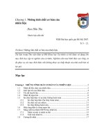
Figure 3.1
ANSI/ASHRAE STANDARD 62.1-2004
3.
DEFINITIONS (see Figure 3.1)
acceptable indoor air quality: air in which there are no known
contaminants at harmful concentrations as determined by
cognizant authorities and with which a substantial majority
(80% or more) of the people exposed do not express dissatisfaction.
air-cleaning system: a device or combination of devices
applied to reduce the concentration of airborne contaminants,
such as microorganisms, dusts, fumes, respirable particles,
other particulate matter, gases, and/or vapors in air.
air conditioning: the process of treating air to meet the
requirements of a conditioned space by controlling its temperature, humidity, cleanliness, and distribution.
air, ambient: the air surrounding a building; the source of
outdoor air brought into a building.
air, exhaust: air removed from a space and discharged to
outside the building by means of mechanical or natural ventilation systems.
air, indoor: the air in an enclosed occupiable space.
air, makeup: any combination of outdoor and transfer air
intended to replace exhaust air and exfiltration.
air, outdoor: ambient air that enters a building through a
ventilation system, through intentional openings for natural
ventilation, or by infiltration.
Ventilation system.
3
air, recirculated: air removed from a space and reused as
supply air.
walls from unconditioned spaces or the outdoors caused by
the same pressure differences that induce exfiltration.
air, return: air removed from a space to be then recirculated
or exhausted.
mechanical ventilation: ventilation provided by mechanically powered equipment, such as motor-driven fans and
blowers, but not by devices such as wind-driven turbine ventilators and mechanically operated windows.
air, supply: air delivered by mechanical or natural ventilation
to a space, composed of any combination of outdoor air, recirculated air, or transfer air.
air, transfer: air moved from one indoor space to another.
air, ventilation: that portion of supply air that is outdoor air
plus any recirculated air that has been treated for the purpose
of maintaining acceptable indoor air quality.
breathing zone: the region within an occupied space between
planes 3 and 72 in. (75 and 1800 mm) above the floor and more
than 2 ft (600 mm) from the walls or fixed air-conditioning
equipment.
cognizant authority: an agency or organization that has the
expertise and jurisdiction to establish and regulate concentration limits for airborne contaminants; or an agency or organization that is recognized as authoritative and has the scope and
expertise to establish guidelines, limit values, or concentrations levels for airborne contaminants.
concentration: the quantity of one constituent dispersed in a
defined amount of another.
conditioned space: that part of a building that is heated or
cooled, or both, for the comfort of occupants.
contaminant: an unwanted airborne constituent that may
reduce acceptability of the air.
energy recovery ventilation system: a device or combination
of devices applied to provide the outdoor air for ventilation in
which energy is transferred between the intake and exhaust
airstreams.
exfiltration: uncontrolled outward air leakage from conditioned spaces through unintentional openings in ceilings,
floors, and walls to unconditioned spaces or the outdoors
caused by pressure differences across these openings due to
wind, inside-outside temperature differences (stack effect),
and imbalances between supply and exhaust airflow rates.
industrial space: an indoor environment where the primary
activity is production or manufacturing processes. The
processes in these spaces may generate contaminants with
characteristics and in quantities dictating that principles of
worker safety and industrial hygiene be used to define
contaminant control strategies, including ventilation. Also,
the primary occupants of these spaces consist of the individuals involved in these processes.
infiltration: uncontrolled inward air leakage to conditioned
spaces through unintentional openings in ceilings, floors, and
4
microorganism: a microscopic organism, especially a bacterium, fungus, or a protozoan.
natural ventilation: ventilation provided by thermal, wind, or
diffusion effects through doors, windows, or other intentional
openings in the building.
net occupiable space: the floor area of an occupiable space
defined by the inside surfaces of its walls but excluding shafts,
column enclosures, and other permanently enclosed, inaccessible, and unoccupiable areas. Obstructions in the space such
as furnishings, display or storage racks, and other obstructions, whether temporary or permanent, may not be deducted
from the space area.
occupiable space: an enclosed space intended for human
activities, excluding those spaces intended primarily for other
purposes, such as storage rooms and equipment rooms, that
are only occupied occasionally and for short periods of time.
odor: a quality of gases, liquids, or particles that stimulates the
olfactory organ.
readily accessible: capable of being reached quickly for operation without requiring those for whom ready access is
required to climb over or remove obstacles or to resort to
portable ladders, chairs, or other climbing aids.
ventilation: the process of supplying air to or removing air
from a space for the purpose of controlling air contaminant
levels, humidity, or temperature within the space.
volume, space: the total volume of an occupiable space
enclosed by the building envelope, plus that of any spaces
permanently open to the occupiable space, such as a ceiling
attic used as a ceiling return plenum.
zone: one occupied space or several occupied spaces with
similar occupancy category (see Table 6-1), occupant density,
zone air distribution effectiveness (see Section 6.2.2.2), and
zone primary airflow (see Section 6.2.5.1) per unit area. Note:
A ventilation zone is not necessarily an independent thermal
control zone; however, spaces that can be combined for load
calculations can often be combined into a single zone for
ventilation calculations.
4.
OUTDOOR AIR QUALITY
Outdoor air quality shall be investigated in accordance
with Sections 4.1 and 4.2 prior to completion of ventilation
system design. The results of this investigation shall be documented in accordance with Section 4.3.
ANSI/ASHRAE STANDARD 62.1-2004
4.1 Regional Air Quality. The status of compliance with
national ambient air quality standards shall be determined for
the geographic area of the building site. In the United States,
compliance status shall be either in “attainment” or “nonattainment” with the National Ambient Air Quality Standards
(NAAQS)1 for each pollutant shown in Table 4-1. In the
United States, areas with no EPA compliance status designation shall be considered “attainment” areas.
4.2 Local Air Quality. An observational survey of the
building site and its immediate surroundings shall be conducted during hours the building is expected to be normally
occupied to identify local contaminants from surrounding
facilities that may be of concern if allowed to enter the building.
4.3 Documentation. Documentation of the outdoor air
quality investigation shall be reviewed with building owners
or their representative and shall include the following:
1.
Regional air quality compliance status. Note: Regional
outdoor air quality compliance status for the United States
is available from the U.S. Environmental Protection
Agency located under www.epa.gov.
2.
Local survey information, which may include the following:
(a)
(b)
(c)
(d)
(e)
(f)
(g)
(h)
Date of observations
Time of observations
Area surveyed
Description of nearby facilities
Observation of odors or irritants
Description of visible plumes or air contaminants
Description of nearby sources of vehicle exhaust
Direction of prevailing winds
3.
Conclusions regarding the acceptability of outdoor air quality based on consideration of information from investigation.
5.
SYSTEMS AND EQUIPMENT
5.1 Natural Ventilation. Use of natural ventilation systems
designed in accordance with this section shall be permitted in
lieu of or in conjunction with mechanical ventilation systems.
Exception to 5.1: An engineered natural ventilation system when approved by the authority having jurisdiction need not meet the requirements of 5.1.1 and
5.1.2.
5.1.1 Location and Size of Openings. Naturally ventilated spaces shall be permanently open to and within 8 m
(25 ft) of operable wall or roof openings to the outdoors,
the openable area of which is a minimum of 4% of the net
occupiable floor area. Where openings are covered with louvers or otherwise obstructed, openable area shall be based
on the free unobstructed area through the opening. Where
interior spaces without direct openings to the outdoors are
ventilated through adjoining rooms, the opening between
rooms shall be permanently unobstructed and have a free area
of not less than 8% of the area of the interior room nor less
than 25 ft2 (2.3 m2).
ANSI/ASHRAE STANDARD 62.1-2004
TABLE 4-1
National Primary Ambient-Air Quality Standards
for Outdoor Air as Set by the
U.S. Environmental Protection Agency
Contaminant
Sulfur dioxide
Particles (PM 10)
Long Term
Short Term
Concentration Averaging
Concentration Averaging
µg/m3
ppm
µg/m3
ppm
0.03
1 year
365a
0.14a
24 hours
1 year
a
—
24 hours
80
50
b
—
150
Carbon monoxide
40,000a
35a
1hour
Carbon monoxide
10,000a
9a
8 hours
Oxidants (ozone)
235c
0.12c
1 hour
Nitrogen dioxide
100
0.055
1 year
Lead
1.5
—
3 monthsd
a Not to be exceeded more than once per year.
b Arithmetic mean.
c Standard is attained when expected number of days per calendar year with maximal hourly average concentrations above 0.12 ppm (235 µg/m3) is equal to or less
than 1, as determined by Appendix H to subchapter C, 40 CFR 50.
d Three-month period is a calendar quarter.
5.1.2 Control and Accessibility. The means to open
required operable openings shall be readily accessible to
building occupants whenever the space is occupied.
5.2 Ventilation Air Distribution. Ventilating systems shall
be designed in accordance with the following:
5.2.1 Designing for Air Balancing. The ventilation air
distribution system shall be provided with means to adjust the
system to achieve at least the minimum ventilation airflow as
required by Section 6 under any load condition.
5.2.2 Plenum Systems. When the ceiling or floor plenum
is used both to recirculate return air and to distribute ventilation air to ceiling-mounted or floor-mounted terminal units,
the system shall be engineered such that each space is provided with its required minimum ventilation airflow. Note:
Direct connection of ventilation air ducts to ventilating terminal units is an alternate method of satisfying the intent of this
requirement.
5.2.3 Documentation. The design documents shall specify minimum requirements for air balance testing or reference
applicable national standards for measurement and balancing
airflow. The design documentation shall state assumptions
that were made in the design with respect to ventilation rates
and air distribution.
5.3 Exhaust Duct Location. Exhaust ducts that convey
potentially harmful contaminants shall be negatively pressurized relative to spaces through which they pass, so that
exhaust air cannot leak into occupied spaces; supply, return,
or outdoor air ducts; or plenums. Exception: Exhaust ducts
that are sealed in accordance with SMACNA Seal Class A.2
5.4 Ventilation System Controls. Mechanical ventilation
systems shall include controls, manual or automatic, that
enable the fan system to operate whenever the spaces served
are occupied. The system shall be designed to maintain the
minimum outdoor airflow as required by Section 6 under any
5
TABLE 5-1
Air Intake Minimum Separation Distance
Object
Minimum Distance, ft (m)
Significantly contaminated exhaust (Note 1)
15 (5)
Noxious or dangerous exhaust (Notes 2 and 3)
30 (10)
Vents, chimneys, and flues from combustion appliances and equipment (Note 4)
15 (5)
Garage entry, automobile loading area, or drive-in queue (Note 5)
15 (5)
Truck loading area or dock, bus parking/idling area (Note 5)
25 (7.5)
Driveway, street, or parking place (Note 5)
5 (1.5)
Thoroughfare with high traffic volume
25 (7.5)
Roof, landscaped grade, or other surface directly below intake (Notes 6 and 7)
1 (0.30)
Garbage storage/pick-up area, dumpsters
15 (5)
Cooling tower intake or basin
15 (5)
Cooling tower exhaust
25 (7.5)
Note 1: Significantly contaminated exhaust is exhaust air with significant contaminant concentration, significant sensory-irritation intensity,
or offensive odor.
Note 2: Laboratory fume hood exhaust air outlets shall be in compliance with NFPA 45-19913 and ANSI/AIHA Z9.5-1992.4
Note 3: Noxious or dangerous exhaust is exhaust air with highly objectionable fumes or gases and/or exhaust air with potentially dangerous
particles, bioaerosols, or gases at concentrations high enough to be considered harmful. Information on separation criteria for industrial environments can be found in the ACGIH Industrial Ventilation Manual 5 and in the ASHRAE Handbook—HVAC Applications.6
Note 4: Shorter separation distances are permitted when determined in accordance with (a) Chapter 7 of ANSI Z223.1/NFPA 54-20027 for
fuel gas burning appliances and equipment; (b) Chapter 6 of NFPA 31-20018 for oil burning appliances and equipment, or (c) Chapter 7 of
NFPA 211-20039 for other combustion appliances and equipment.
Note 5: Distance measured to closest place that vehicle exhaust is likely to be located.
Note 6: No minimum separation distance applies to surfaces that are sloped more than 45 degrees from horizontal or that are less than 1 in.
(3 cm) wide.
Note 7: Where snow accumulation is expected, distance listed shall be increased by the expected average snow depth.
load condition. Note: VAV systems with fixed outdoor air
damper positions must comply with this requirement at minimum supply airflow.
5.5 Airstream Surfaces. All airstream surfaces in equipment and ducts in the heating, ventilating, and air-conditioning system shall be designed and constructed in accordance
with the following requirements.
5.5.1 Resistance to Mold Growth. Material surfaces
shall be determined to be resistant to mold growth in accordance with a standardized test method, such as the “Mold
Growth and Humidity Test” in UL 181,10 ASTM C 1338,11 or
comparable test methods.
Exception to 5.5.1: Sheet metal surfaces and metal fastners.
Note: Even with this resistance, any airstream surface
that is continuously wetted is still subject to microbial growth.
5.5.2 Resistance to Erosion. Airstream surface materials
shall be evaluated in accordance with the “Erosion Test” in
UL 18110 and shall not break away, crack, peel, flake off, or
show evidence of delamination or continued erosion under
test conditions.
Exception to 5.5.2: Sheet metal surfaces and metal fasteners.
5.6 Outdoor Air Intakes. Ventilation system outdoor
intakes shall be designed in accordance with the following.
6
5.6.1 Location. Outdoor air intakes, including doors and
windows that are required as part of a natural ventilation system, shall be located such that the shortest distance from the
intake to any specific potential outdoor contaminant source
shall be equal to or greater than the separation distance listed
in Table 5-1. Exception: Other minimum separation distances are acceptable if it can be shown that an equivalent or
lesser rate of introduction of outdoor air contaminants will be
attained. Note: Appendix F presents an acceptable alternative
method of determining the minimum separation distance.
5.6.2 Rain Entrainment. Outdoor air intakes that are part
of the mechanical ventilation system shall be designed to
manage rain entrainment in accordance with any one of the
following:
(a) Limit water penetration through the intake to
0.07 oz/ft2⋅h (21.5 g/m2⋅h) of inlet area when
tested using the rain test apparatus described in
Section 58 of UL 1995.12
(b) Select louvers that limit water penetration to a
maximum of 0.01 oz/ft2 (3 g/m2) of louver free
area at the maximum intake velocity. This
water penetration rate shall be determined for a
minimum 15-minute test duration when subjected to a water flow rate of 0.25 gal/min (16
mL/s) as described under the Water Penetration
Test in AMCA 500-L-9913 or equivalent. Manage the water that penetrates the louver by providing a drainage area and/or moisture removal
devices.
ANSI/ASHRAE STANDARD 62.1-2004
(c) Select louvers that restrict wind-driven rain penetration to less than 2.36 oz/ft2⋅h (721 g/m2⋅h)
when subjected to a simulated rainfall of 3 in.
(75 mm) per hour and a 29 mph (13 m/s) wind
velocity at the design outdoor air intake rate with
the air velocity calculated based on the louver
face area. Note: This performance corresponds
to Class A (99% effectiveness) when rated
according to AMCA 511-9914 and tested per
AMCA 500-L-99.13
(d) Use rain hoods sized for no more than 500 fpm
(2.5 m/s) face velocity with a downward-facing
intake such that all intake air passes upward
through a horizontal plane that intersects the
solid surfaces of the hood before entering the
system.
(e) Manage the water that penetrates the intake
opening by providing a drainage area and/or
moisture removal devices.
5.6.3 Rain Intrusion. Air handling and distribution
equipment mounted outdoors shall be designed to prevent rain
intrusion into the airstream when tested at design airflow and
with no airflow, using the rain test apparatus described in Section 58 of UL 1995.12
5.6.4 Snow Entrainment. Where climate dictates, outdoor air intakes that are part of the mechanical ventilation system shall be designed to manage melted snow blown or drawn
into the system as follows:
(a) Suitable access doors to permit cleaning shall
be provided.
(b) Outdoor air ductwork or plenums shall pitch to
drains designed in accordance with the requirements of Section 5.11.
5.6.5 Bird Screens. Outdoor air intakes shall include a
screening device designed to prevent penetration by a 1/2 in.
(13 mm) diameter probe. The screening device material shall
be corrosion resistant. The screening device shall be located,
or other measures shall be taken, to prevent bird nesting
within the outdoor air intake. Note: Any horizontal surface
may be subject to bird nesting.
5.7 Local Capture of Contaminants. The discharge from
non-combustion equipment that captures the contaminants
generated by the equipment shall be ducted directly to the outdoors.
Exception: Equipment specifically designed for discharge
indoors in accordance with the manufacturer’s
recommendations.
5.8 Combustion Air. Fuel-burning appliances, both vented
and unvented, shall be provided with sufficient air for combustion and adequate removal of combustion products, in
accordance with manufacturer instructions. Products of combustion from vented appliances shall be vented directly outdoors.
5.9 Particulate Matter Removal. Particulate matter filters
or air cleaners having a minimum efficiency reporting value
(MERV) of not less than 6 when rated in accordance with
ANSI/ASHRAE Standard 52.2-199915 shall be provided
upstream of all cooling coils or other devices with wetted surfaces through which air is supplied to an occupiable space.
ANSI/ASHRAE STANDARD 62.1-2004
5.10 Dehumidification Systems. Mechanical air-conditioning systems with dehumidification capability shall be
designed to comply with the following:
5.10.1 Relative Humidity. Occupied space relative
humidity shall be designed to be limited to 65% or less at
either of the two following design conditions:
1.
at the peak outdoor dew-point design conditions and at the
peak indoor design latent load or
2.
at the lowest space sensible heat ratio expected to occur and
the concurrent (simultaneous) outdoor condition.
Note: The outdoor air dry bulb, solar load, and space sensible
heat ratio may be significantly different at outdoor dew-point
design conditions than when calculated at outdoor dry-bulb
design conditions.
5.10.2 Exfiltration. For a building, the design minimum
outdoor air intake shall be greater than the design maximum
exhaust airflow when the mechanical air-conditioning systems are dehumidifying. Note: Although individual zones
within the building may be neutral or negative, such as some
laboratory and industrial spaces, the requirement is for the
building as a whole to limit excessive infiltration of high dew
point outdoor air.
5.11 Drain Pans. Drain pans, including their outlets and
seals, shall be designed and constructed in accordance with
this section.
5.11.1 Drain Pan Slope. Pans intended to collect and
drain liquid water shall be sloped at least 1/8 in. per foot
(10 mm per meter) from the horizontal toward the drain outlet
or shall be otherwise designed to ensure that water drains
freely from the pan whether the fan is on or off.
5.11.2 Drain Outlet. The drain pan outlet shall be located
at the lowest point(s) of the drain pan and shall be of sufficient
diameter to preclude drain pan overflow under any normally
expected operating condition.
5.11.3 Drain Seal. For configuration that result in negative static pressure at the drain pan relative to the drain outlet
(such as a draw-through unit), the drain line shall include a Ptrap or other sealing device designed to maintain a seal against
ingestion of ambient air while allowing complete drainage of
the drain pan under any normally expected operating condition, whether the fan is on or off.
5.11.4 Pan Size. The drain pan shall be located under the
water-producing device. Drain pan width shall be sufficient to
collect water droplets across the entire width of the water-producing device or assembly. For horizontal airflow configurations, the drain pan length shall begin at the leading face or
edge of the water-producing device or assembly and extend
downstream from the leaving face or edge to a distance of
either:
(a) one half of the installed vertical dimension of the waterproducing device or assembly, or
(b) as necessary to limit water droplet carryover beyond the
drain pan to 0.0044 oz per ft2 (1.5 mL per m2) of face
area per hour under peak sensible and peak dew point
design conditions, considering both latent load and coil
face velocity.
7
5.12 Finned-Tube Coils and Heat Exchangers
5.12.1 Drain Pans. A drain pan in accordance with Section 5.11 shall be provided beneath all dehumidifying cooling
coil assemblies and all condensate-producing heat exchangers.
5.12.2 Finned-Tube Coil Selection for Cleaning. Individual finned-tube coils or multiple finned-tube coils in series
without adequate intervening access space(s) of at least 18 in.
(457 mm) shall be selected to result in no more than 0.75
in.wc (187 Pa) combined pressure drop when dry coil face
velocity is 500 fpm (2.54 m/s).
Exception: When clear and complete instructions for access
and cleaning of both upstream and downstream
coil surfaces are provided.
5.13 Humidifiers and Water-Spray Systems. Steam and
direct evaporation humidifiers, air washers, and other waterspray systems shall be designed in accordance with this section.
5.13.1 Water Quality. Water shall originated directly
from a potable source or from a source with equal or better
water quality.
5.13.2 Obstructions. Air cleaners or ductwork obstructions, such as turning vanes, volume dampers, and duct offsets
greater than 15 degrees, that are installed downstream of
humidifiers or water spray systems shall be located a distance
equal to or greater than the absorption distance recommended
by the humidifier or water spray system manufacturer.
Exception: Equipment such as eliminators, coils, or evaporative media may be located within the absorption
distance
recommended
by
the
manufacturer, provided a drain pan complying
with the requirements of Section 5.11 is used to
capture and remove any water that may drop out
of the airstream due to impingement on these
obstructions.
5.14 Access for Inspection, Cleaning, and Maintenance
5.14.1 Equipment Clearance. Ventilation equipment
shall be installed with sufficient working space for inspection
and routine maintenance (e.g., filter replacement and fan belt
adjustment and replacement).
5.14.2 Ventilation Equipment Access. Access doors,
panels, or other means shall be provided and sized to allow
convenient and unobstructed access sufficient to inspect,
maintain, and calibrate all ventilation system components for
which routine inspection, maintenance, or calibration is necessary. Ventilation system components comprise, for example, air-handling units, fan-coil units, water-source heat
pumps, other terminal units, controllers, and sensors.
5.14.3 Air Distribution System. Access doors, panels, or
other means shall be provided in ventilation equipment, ductwork, and plenums, located and sized to allow convenient and
unobstructed access for inspection, cleaning, and routine
maintenance of the following:
(a) Outdoor air intake areaways or plenums
(b) Mixed air plenums
8
(c) Upstream surface of each heating, cooling, and heatrecovery coil or coil assembly having a total of four rows
or less
(d) Both upstream and downstream surface of each heating,
cooling, and heat-recovery coil having a total of more
than four rows and air washers, evaporative coolers, heat
wheels, and other heat exchangers
(e) Air cleaners
(f) Drain pans and drain seals
(g) Fans
(h) Humidifiers
5.15 Building Envelope and Interior Surfaces. The building envelope and interior surfaces within the building envelope shall be designed in accordance with the following.
5.15.1 Building Envelope. The building envelope,
including roofs, walls, fenestration systems, and foundations,
shall comply with the following:
1.
A weather barrier or other means shall be provided to
prevent liquid water penetration into the envelope. Exception: When the envelope is engineered to allow incidental
water penetration to occur without resulting in damage to
the envelope construction.
2.
An appropriately placed vapor retarder or other means shall
be provided to limit water vapor diffusion to prevent
condensation on cold surfaces within the envelope. Exception: When the envelope is engineered to manage incidental
condensation without resulting in damage to the envelope
construction.
3.
Exterior joints, seams, or penetrations in the building envelope that are pathways for air leakage shall be caulked,
gasketed, weather-stripped, provided with continuous air
barrier, or otherwise sealed to limit infiltration through the
envelope to reduce uncontrolled entry of outdoor air moisture and pollutants.
Note: Where soils contain high concentrations of radon or
other soil gas contaminants, the local authority having jurisdiction may have additional requirements, such as depressurization.
5.15.2 Condensation on Interior Surfaces. Pipes, ducts,
and other surfaces within the building whose surface temperatures are expected to fall below the surrounding dew-point
temperature shall be insulated. The insulation system thermal
resistance and material characteristics shall be sufficient to
prevent condensation from forming on the exposed surface
and within the insulating material.
Exceptions:
1. Where condensate will wet only surfaces that can be
managed to prevent or control mold growth.
2. Where local practice has demonstrated that condensation
does not result in mold growth.
5.16 Buildings with Attached Parking Garages. In order
to limit the entry of vehicular exhaust into occupiable spaces,
buildings with attached parking garages shall:
1. maintain the garage pressure at or below the pressure of the
adjacent occupiable spaces; or
ANSI/ASHRAE STANDARD 62.1-2004
2.
use a vestibule to provide an airlock between the garage and
the adjacent occupiable spaces; or
3.
otherwise be designed to minimize migration of air from
the attached parking garage into the adjacent occupiable
spaces of the building.
5.17 Air Classification and Recirculation. Air shall be
classified, and its recirculation shall be limited in accordance
with the following sections.
5.17.1 Classification. Air (return, transfer, or exhaust air)
leaving each space or location shall be designated at an
expected air-quality classification not less than that shown in
Table 6-1, Table 5-2, or Table 5-3 or as approved by the
authority having jurisdiction. The classification for air from
spaces or locations that are not listed in Table 6-1, Table 5-2,
or Table 5-3 shall be the same as the classification for air from
TABLE 5-2
Air Class
Spaces ancillary to Class 2 spaces
2
Kitchenettes
2
Break rooms
1
Coffee stations
1
Private toilet/bath
2
Employee locker rooms
2
Storage rooms, chemical
4
Equipment rooms
1
Electrical/telephone closets
1
Elevator machine rooms
1
Refrigerating machinery rooms
3
Laundry rooms, central
2
Laundry rooms within dwelling units
1
Soiled laundry storage
3
Janitors closet, trash room
3
General chemical/biological laboratories
3
University/college laboratories
2
Paint spray booths
4
Daycare sickroom
3
TABLE 5-3
Airstreams
Description
Air Class
Diazo printing equipment discharge
4
Commercial kitchen grease hoods
4
Commercial kitchen hoods other than grease
3
Laboratory hoods
4
Residential kitchen vented hoods
3
ANSI/ASHRAE STANDARD 62.1-2004
•
•
•
Other Space Types
Description
the listed space type that is most similar in terms of occupant
activities and building construction. Exception: Classification of air from smoking spaces is not addressed. (Spaces that
are expected to include smoking do not have a classification
listed in Table 6-1.)
Note: Classifications in Table 6-1, Table 5-2, and Table 5-3
are based on relative contaminant concentration using the following subjective criteria:
•
Class 1: Air with low contaminant concentration, low
sensory-irritation intensity, and inoffensive odor.
Class 2: Air with moderate contaminant concentration,
mild sensory-irritation intensity, or mildly offensive
odors. Class 2 air also includes air that is not necessarily
harmful or objectionable but that is inappropriate for
transfer or recirculation to spaces used for different purposes.
Class 3: Air with significant contaminant concentration,
significant sensory-irritation intensity, or offensive odor.
Class 4: Air with highly objectionable fumes or gases or
with potentially dangerous particles, bioaerosols, or
gases, at concentrations high enough to be considered
harmful.
5.17.2 Re-designation.
5.17.2.1 Air Cleaning. If air leaving a space or location
passes through an air-cleaning system, the cleaned air may be
reclassified to a cleaner classification, using the subjective
criteria noted above, with the approval of the authority having
jurisdiction.
5.17.2.2 Energy Recovery. Class 2 air may be re-designated as Class 1 air in the process of recovering energy when
it is diluted with outdoor air such that no more than 10% of the
resulting airstream is Class 2 air. Class 3 air may be re-designated as Class 1 air in the process of recovering energy when
it is diluted with outdoor air such that no more than 5% of the
resulting airstream is Class 3 air.
5.17.2.3 Transfer. A mixture of air that has been transferred through or returned from more than one classification
of space must be re-designated with the classification appropriate for the part of the mixture that has the highest contaminant concentration. For example, air returned from both a
Class 1 and a Class 2 space served by a common system must
be designated as Class 2 air.
5.17.3 Recirculation Limitations. When the Ventilation
Rate Procedure of Section 6 is used to determine ventilation airflow values, recirculation of air shall be limited in accordance
with the requirements of this section.
5.17.3.1 Class 1 Air. Class 1 air may be recirculated or
transferred to any space.
5.17.3.2 Class 2 Air. Class 2 air may be recirculated
within the space of origin. Class 2 air may be transferred or
recirculated to other Class 2 or Class 3 spaces utilized for the
same or similar purpose or task and involving the same or similar pollutant sources. Class 2 air may be recirculated or transferred to Class 4 spaces. Class 2 air shall not be recirculated or
transferred to Class 1 spaces. Note: Spaces that are normally
Class 1 may be identified as “Spaces ancillary to Class 2
spaces” and as such classified as Class 2 spaces as permitted
in Table 6-1.
9
5.17.3.3 Class 3 Air. Class 3 air may be recirculated
within the space of origin. Class 3 air shall not be recirculated or
transferred to any other space.
5.17.3.4 Class 4 Air. Class 4 air shall not be recirculated
or transferred to any space nor recirculated within the space of
origin.
5.17.4 Documentation. Design documentation shall indicate the justification for classification of air from any location
not listed in Table 6-1, Table 5-2, or Table 5-3.
6.
PROCEDURES
This section is not required for natural ventilation
systems; natural ventilation systems shall be designed in
accordance with Section 5.1.
6.1 General. Either the Ventilation Rate Procedure or the
IAQ Procedure shall be used to design each ventilation system
in a building, subject to the following considerations and
restrictions.
6.1.1 Ventilation Rate Procedure. This is a prescriptive
procedure in which outdoor air intake rates are determined
based on space type/application, occupancy level, and floor
area. Note: The Ventilation Rate Procedure minimum rates
are based on contaminant sources and source strengths that
are typical for the listed space types.
6.1.2 IAQ Procedure. This is a design procedure in
which outdoor air intake rates and other system design parameters are based on an analysis of contaminant sources, contaminant concentration targets, and perceived acceptability
targets. The IAQ Procedure allows credit to be taken for controls that remove contaminants (for example, air cleaning
devices) or for other design techniques (for example, selection of materials with lower source strengths) that can be reliably demonstrated to result in indoor contaminant
concentrations equal to or lower than those achieved using the
Ventilation Rate Procedure. The IAQ Procedure may also be
used where the design is intended to attain specific target contaminant concentrations or levels of acceptability of perceived
indoor air quality.
6.2.1.1 Particulate Matter. When the building is
located in an area where the national standard for PM10 is
exceeded, particle filters or air cleaning devices shall be provided to clean the air at any location prior to its introduction
to occupied spaces. Particulate matter filters or air cleaners
shall have a Minimum Efficiency Reporting Value (MERV) of
6 or higher when rated in accordance with ASHRAE Standard
52.2-1999.15
6.2.1.2 Ozone. Air-cleaning devices for ozone shall be
provided when the second-highest daily maximum one-hour
average concentration exceeds 0.160 ppm (313 µg/m3). The
ozone concentration for design purposes shall be determined
in accordance with Appendix H to subchapter C, 40 CFR 50,1
or equivalent.
Note: Monitored values for historical one-hour average
ozone concentrations are available for United States locations
at the AIRData Web site, located under www.epa.gov.
Such air-cleaning devices shall have a minimum volumetric ozone removal efficiency of 40% when installed, operated,
and maintained in accordance with manufacturer recommendations and shall be approved by the authority having jurisdiction. Such devices shall be operated whenever outdoor
ozone levels are expected to exceed 0.160 ppm (313 µg/m3).
Note: For United States locations, the one-hour average
ozone concentration is expected to exceed the 0.160 ppm (313
µg/m3) limit when the Air Quality Index forecast exceeds 151
(category red, purple, or maroon). This forecast is available in
local media or at the AIRNow Web site, located under
www.epa.gov.
Exceptions:
Air cleaning for ozone is not required when:
1.
The minimum system design outdoor air intake flow
results in 1.5 air changes per hour or less.
2.
Controls are provided that sense outdoor ozone level
and reduce intake airflow to result in 1.5 air changes
per hour or less while complying with the outdoor
airflow requirements of Section 6.
3.
Outdoor air is brought into the building and heated by
direct-fired, makeup air units.
6.2
Ventilation Rate Procedure
The design outdoor air intake flow (Vot) for a ventilation
system shall be determined in accordance with Sections 6.2.1
through 6.2.9.
Note: Additional explanation of terms used below is
contained in Appendix A, along with a ventilation system
schematic (Figure A.1).
6.2.1 Outdoor Air Treatment. If outdoor air is judged to
be unacceptable in accordance with Section 4.1, each ventilation system that provides outdoor air through a supply fan
shall comply with the following sections.
Exceptions: Systems supplying air for enclosed parking
garages, warehouses, storage rooms, janitor’s
closets, trash rooms, recycling areas, shipping/
receiving/distribution areas.
Note: Occupied spaces ventilated with outdoor air that is
judged to be unacceptable are subject to reduced air quality
when outdoor air is not cleaned prior to introduction to the
occupied spaces.
10
6.2.1.3 Other Outdoor Contaminants. When the
building is located in an area where the national standard for
one or more contaminants not specifically addressed in Section 6.2.1 is exceeded, any design assumptions and/or calculations related to the impact on indoor air quality shall be
included in the design documents.
6.2.2 Zone Calculations. Zone parameters shall be determined in accordance with Sections 6.2.2.1 through 6.2.2.3.
Note: In some cases it is acceptable to determine these
parameters for only selected zones as outlined in Appendix A.
6.2.2.1 Breathing Zone Outdoor Airflow. The design
outdoor airflow required in the breathing zone of the occupiable space or spaces in a zone, i.e., the breathing zone outdoor
airflow (Vbz), shall be determined in accordance with Equation 6-1.
Vbz = RpPz + RaAz
(6-1)
where:
ANSI/ASHRAE STANDARD 62.1-2004
Az =
zone floor area: the net occupiable floor area of the
zone m2, (ft2).
Pz = zone population: the largest number of people
expected to occupy the zone during typical usage. If
the number of people expected to occupy the zone
fluctuates, Pz may be estimated based on averaging
approaches described in Section 6.2.6.2. Note: If Pz
cannot be accurately predicted during design, it shall
be an estimated value based on the zone floor area and
the default occupant density listed in Table 6-1.
Rp = outdoor airflow rate required per person as determined
from Table 6-1. Note: These values are based on
adapted occupants.
Ra = outdoor airflow rate required per unit area as
determined from Table 6-1.
Note: Equation 6-1 is the means of accounting for peoplerelated sources and area-related sources for determining the
outdoor air required at the breathing zone. The use of Equation
6-1 in the context of this standard does not necessarily imply
that simple addition of sources can be applied to any other
aspect of indoor air quality.
6.2.2.2 Zone Air Distribution Effectiveness. The zone
air distribution effectiveness (Ez) shall be determined using
Table 6-2.
6.2.2.3 Zone Outdoor Airflow. The design zone outdoor airflow (Voz), i.e., the outdoor airflow that must be provided to the zone by the supply air distribution system, shall
be determined in accordance with Equation 6-2.
Voz = Vbz/Ez
(6-2)
6.2.3 Single-Zone Systems. When one air handler supplies a mixture of outdoor air and recirculated air to only one
zone, the outdoor air intake flow (Vot) shall be determined in
accordance with Equation 6-3.
Vot = Voz
(6-3)
6.2.4 100% Outdoor Air Systems. When one air handler
supplies only outdoor air to one or more zones, the outdoor
air intake flow (Vot) shall be determined in accordance with
Equation 6-4.
Vot = Σall zonesVoz
(6-4)
6.2.5 Multiple-Zone Recirculating Systems. When one
air handler supplies a mixture of outdoor air and recirculated
return air to more than one zone, the outdoor air intake flow
(Vot) shall be determined in accordance with Sections 6.2.5.1
through 6.2.5.4.
6.2.5.1 Primary Outdoor Air Fraction. When Table 6-3
is used to determine system ventilation efficiency, the zone primary outdoor air fraction (Zp) shall be determined in accordance with Equation 6-5.
6.2.5.3 Uncorrected Outdoor Air Intake. The design
uncorrected outdoor air intake (Vou) shall be determined in
accordance with Equation 6-6.
Vou = D Σall zones RpPz + Σall zones RaAz
(6-6)
The occupant diversity, D, may be used to account for
variations in occupancy within the zones served by the system.
The occupancy diversity is defined as
D = Ps/Σall zones Pz
(6-7)
where the system population (Ps) is the total population in the
area served by the system. Alternative methods may be used
to account for population diversity when calculating Vou,
provided that the resulting value is no less than that determined by Equation 6-6.
Note: The uncorrected outdoor air intake (Vou) is
adjusted for diversity but uncorrected for ventilation efficiency.
6.2.5.4 Outdoor Air Intake. The design outdoor air
intake flow (Vot) shall be determined in accordance with
Equation 6-8.
Vot = Vou/Ev
(6-8)
6.2.6 Design for Varying Operating Conditions.
6.2.6.1 Variable Load Conditions. Ventilation systems
shall be designed to be capable of providing the required ventilation rates in the breathing zone whenever the zones served
by the system are occupied, including all full- and part-load
conditions.
6.2.6.2 Short-Term Conditions. If it is known that
peak occupancy will be of short duration and/or ventilation
will be varied or interrupted for a short period of time, the
design may be based on the average conditions over a time
period T determined by Equation 6-9:
T = 3 v / Vbz
(6-9a) IP
T = 50 v / Vbz
(6-9b) SI
where:
T = averaging time period, (min).
v
= the volume of the zone for which averaging is being
applied, ft3 (m3).
Vbz = the breathing zone outdoor airflow calculated using
Equation 6-1 and the design value of the zone
population Pz, cfm (L/s).
Acceptable design adjustments based on this optional
provision include the following:
1.
Zones with fluctuating occupancy: The zone population
(Pz) may be averaged over time T.
(6-5)
2.
where Vpz is the zone primary airflow, i.e., the primary airflow
to the zone from the air handler including outdoor air and
recirculated return air. Note: For VAV systems, Vpz is the
minimum expected primary airflow for design purposes.
6.2.5.2 System Ventilation Efficiency. The system ventilation efficiency (Ev) shall be determined using Table 6-3 or
Appendix A.
Zones with intermittent interruption of supply air: The average outdoor airflow supplied to the breathing zone over
time T shall be no less than the breathing zone outdoor
airflow (Vbz) calculated using Equation 6-1.
3.
Systems with intermittent closure of the outdoor air intake:
The average outdoor air intake over time T shall be no less
than the minimum outdoor air intake (Vot) calculated using
Equation 6-3, 6-4, or 6-8 as appropriate.
Zp = Voz/Vpz
ANSI/ASHRAE STANDARD 62.1-2004
11
TABLE 6-1 MINIMUM VENTILATION RATES IN BREATHING ZONE
(This table is not valid in isolation; it must be used in conjunction with the accompanying notes.)
Default Values
People Outdoor Air Rate
Rp
Area Outdoor
Air Rate Ra
Occupancy Category
Notes
cfm/person L/s•person cfm/ft2
Occupant
Density
(see Note 4)
Combined Outdoor Air
Rate (see Note 5)
L/s•m2
#/1000 ft2
or #/100 m2
cfm/person
L/s•person
Air
Class
Correctional Facilities
Cell
5
2.5
0.12
0.6
25
10
4.9
2
Day room
5
2.5
0.06
0.3
30
7
3.5
1
Guard stations
5
2.5
0.06
0.3
15
9
4.5
1
7.5
3.8
0.06
0.3
50
9
4.4
2
Daycare (through age 4)
10
5
0.18
0.9
25
17
8.6
2
Classrooms (ages 5-8)
10
5
0.12
0.6
25
15
7.4
1
Classrooms (age 9 plus)
10
5
0.12
0.6
35
13
6.7
1
Lecture classroom
7.5
3.8
0.06
0.3
65
8
4.3
1
Lecture hall (fixed seats)
7.5
3.8
0.06
0.3
150
8
4.0
1
Art classroom
10
5
0.18
0.9
20
19
9.5
2
Science laboratories
10
5
0.18
0.9
25
17
8.6
-
Wood/metal shop
10
5
0.18
0.9
20
19
9.5
2
Computer lab
10
5
0.12
0.6
25
15
7.4
1
Media center
10
5
0.12
0.6
25
15
7.4
1
Music/theater/dance
10
5
0.06
0.3
35
12
5.9
1
Multi-use assembly
7.5
3.8
0.06
0.3
100
8
4.1
1
Restaurant dining rooms
7.5
3.8
0.18
0.9
70
10
5.1
2
Cafeteria/fast food dining
7.5
3.8
0.18
0.9
100
9
4.7
2
Bars, cocktail lounges
7.5
3.8
0.18
0.9
100
9
4.7
2
Conference/meeting
5
2.5
0.06
0.3
50
6
3.1
1
Corridors
-
-
0.06
0.3
-
1
Storage rooms
-
-
0.12
0.6
-
1
Booking/waiting
Educational Facilities
E
A
Food and Beverage Service
General
B
Hotels, Motels, Resorts, Dormitories
Bedroom/living Room
5
2.5
0.06
0.3
10
11
5.5
1
Barracks sleeping areas
5
2.5
0.06
0.3
20
8
4.0
1
7.5
3.8
0.06
0.3
30
10
4.8
1
5
2.5
0.06
0.3
120
6
2.8
1
Lobbies/prefunction
Multi-purpose assembly
12
ANSI/ASHRAE STANDARD 62.1-2004
TABLE 6-1 MINIMUM VENTILATION RATES IN BREATHING ZONE (Continued)
(This table is not valid in isolation; it must be used in conjunction with the accompanying notes.)
Default Values
People Outdoor Air Rate
Rp
Area Outdoor
Air Rate Ra
Occupancy Category
Notes
cfm/person L/s•person cfm/ft2
Occupant
Density
(see Note 4)
Combined Outdoor Air
Rate (see Note 5)
L/s•m2
#/1000 ft2
or #/100 m2
cfm/person
L/s•person
Air
Class
Office Buildings
Office space
5
2.5
0.06
0.3
5
17
8.5
1
Reception areas
5
2.5
0.06
0.3
30
7
3.5
1
Telephone/data entry
5
2.5
0.06
0.3
60
6
3.0
1
Main entry lobbies
5
2.5
0.06
0.3
10
11
5.5
1
Bank vaults/safe deposit
5
2.5
0.06
0.3
5
17
8.5
2
Computer (not printing)
5
2.5
0.06
0.3
4
20
10.0
1
Pharmacy (prep. area)
5
2.5
0.18
0.9
10
23
11.5
2
Photo studios
5
2.5
0.12
0.6
10
17
8.5
1
Shipping/receiving
-
-
0.12
0.6
7.5
3.8
0.06
0.3
-
-
0.06
0.3
Auditorium seating area
5
2.5
0.06
0.3
150
5
2.7
1
Places of religious workshop
5
2.5
0.06
0.3
120
6
2.8
1
Courtrooms
5
2.5
0.06
0.3
70
6
2.9
1
Legislative chambers
5
2.5
0.06
0.3
50
6
3.1
1
Libraries
5
2.5
0.12
0.6
10
17
8.5
1
Lobbies
5
2.5
0.06
0.3
150
5
2.7
1
Museums (children’s)
7.5
3.8
0.12
0.6
40
11
5.3
1
Museums/galleries
7.5
3.8
0.06
0.3
40
9
4.6
1
Sales (except as below)
7.5
3.8
0.12
0.6
15
16
7.8
2
Mall common areas
7.5
3.8
0.06
0.3
40
9
4.6
1
Barber shop
7.5
3.8
0.06
0.3
25
10
5.0
2
Beauty and nail salons
20
10
0.12
0.6
25
25
12.4
2
Pet shops (animal areas)
7.5
3.8
0.18
0.9
10
26
12.8
2
Supermarket
7.5
3.8
0.06
0.3
8
15
7.6
1
Coin-operated laundries
7.5
3.8
0.06
0.3
20
11
5.3
2
Miscellaneous Spaces
Transportation waiting
Warehouses
B
100
B
1
8
4.1
-
1
2
Public Assembly Spaces
Retail
ANSI/ASHRAE STANDARD 62.1-2004
13
TABLE 6-1 MINIMUM VENTILATION RATES IN BREATHING ZONE (Continued)
(This table is not valid in isolation; it must be used in conjunction with the accompanying notes.)
Default Values
People Outdoor Air Rate
Rp
Area Outdoor
Air Rate Ra
Occupancy Category
Notes
cfm/person L/s•person cfm/ft2
Occupant
Density
(see Note 4)
L/s•m2
#/1000 ft2
or #/100 m2
Combined Outdoor Air
Rate (see Note 5)
cfm/person
Air
Class
L/s•person
Sports and Entertainment
Sports arena (play area)
-
-
0.30
1.5
-
1
Gym, stadium (play area)
-
-
0.30
1.5
30
2
7.5
3.8
0.06
0.3
150
-
-
0.48
2.4
Disco/dance floors
20
10
0.06
0.3
100
21
10.3
1
Health club/aerobics room
20
10
0.06
0.3
40
22
10.8
2
Health club/weight rooms
20
10
0.06
0.3
10
26
13.0
2
Bowling alley (seating)
10
5
0.12
0.6
40
13
6.5
1
Gambling casinos
7.5
3.8
0.18
0.9
120
9
4.6
1
Game arcades
7.5
3.8
0.18
0.9
20
17
8.3
1
Stages, studios
10
5
0.06
0.3
70
11
5.4
1
Spectator areas
Swimming (pool & deck)
C
D
8
4.0
-
1
2
GENERAL NOTES FOR TABLE 6-1
1 Related Requirements: The rates in this table are based on all other applicable requirements of this standard being met.
2 Smoking: This table applies to no-smoking areas. Rates for smoking-permitted spaces must be determined using other methods. See
Section 6.2.9 for ventilation requirements in smoking areas.
3 Air Density: Volumetric airflow rates are based on an air density of 0.075 lbda/ft3 (1.2 kgda/m3), which corresponds to dry air at a barometric pressure of 1 atm (101.3 kPa) and an air temperature of 70°F (21°C). Rates may be adjusted for actual density but such adjustment
is not required for compliance with this standard.
4 Default Occupant Density: The default occupant density shall be used when actual occupant density is not known.
5 Default Combined Outdoor Air Rate (per person): This rate is based on the default occupant density.
6 Unlisted Occupancies: If the occupancy category for a proposed space or zone is not listed, the requirements for the listed occupancy category that is most similar in terms of occupant density, activities and building construction shall be used.
7 Residential facilities, Healthcare facilities and Vehicles: Rates shall be determined in accordance with Appendix E.
ITEM-SPECIFIC NOTES FOR TABLE 6-1
A For high school and college libraries, use values shown for Public Spaces – Library.
B Rate may not be sufficient when stored materials include those having potentially harmful emissions.
C Rate does not allow for humidity control. Additional ventilation or dehumidification may be required to remove moisture.
D Rate does not include special exhaust for stage effects, e.g., dry ice vapors, smoke.
E No class of air has been established for this occupancy category.
14
ANSI/ASHRAE STANDARD 62.1-2004
TABLE 6-2
Zone Air Distribution Effectiveness
Air Distribution Configuration
TABLE 6-3
System Ventilation Efficiency
Ez
Max (ZP)
Ev
Ceiling supply of cool air
1.0
≤ 0.15
1.0
Ceiling supply of warm air and floor return
1.0
≤ 0.25
0.9
Ceiling supply of warm air 15°F (8°C) or more above
space temperature and ceiling return.
0.8
≤ 0.35
0.8
≤ 0.45
0.7
Ceiling supply of warm air less than 15°F (8°C) above
space temperature and ceiling return provided that the
150 fpm (0.8 m/s) supply air jet reaches to within 4.5 ft
(1.4 m) of floor level. Note: For lower velocity supply
air, Ez = 0.8.
1.0
≤ 0.55
0.6
> 0.55
Use Appendix A
Floor supply of cool air and ceiling return provided that
the 150 fpm (0.8 m/s) supply jet reaches 4.5 ft (1.4 m) or
more above the floor. Note: Most underfloor air distribution systems comply with this proviso.
1.0
Floor supply of cool air and ceiling return, provided lowvelocity displacement ventilation achieves unidirectional
flow and thermal stratification
1.2
Floor supply of warm air and floor return
1.0
Floor supply of warm air and ceiling return
0.7
Makeup supply drawn in on the opposite side of the
room from the exhaust and/or return
0.8
Makeup supply drawn in near to the exhaust and/or
return location
0.5
1. “Cool air” is air cooler than space temperature.
2. “Warm air” is air warmer than space temperature.
3. “Ceiling” includes any point above the breathing zone.
4. “Floor” includes any point below the breathing zone.
5. As an alternative to using the above values, Ez may be regarded as equal to air
change effectiveness determined in accordance with ASHRAE Standard 12916 for
all air distribution configurations except unidirectional flow.
6.2.7 Dynamic Reset. The system may be designed to
reset the design outdoor air intake flow (Vot) and/or space or
zone airflow as operating conditions change. These conditions include but are not limited to:
1.
Variations in occupancy or ventilation airflow in one or
more individual zones for which ventilation airflow
requirements will be reset. Note: Examples of measures for
estimating such variations include: occupancy scheduled
by time-of-day, a direct count of occupants, or an estimate
of occupancy or ventilation rate per person using occupancy sensors such as those based on indoor CO2 concentrations.
2.
Variations in the efficiency with which outdoor air is
distributed to the occupants under different ventilation
system airflows and temperatures.
3.
A higher fraction of outdoor air in the air supply due to
intake of additional outdoor air for free cooling or exhaust
air makeup.
6.2.8 Exhaust Ventilation. Exhaust airflow shall be provided in accordance with the requirements in Table 6-4.
Exhaust makeup air may be any combination of outdoor air,
recirculated air, and transfer air.
ANSI/ASHRAE STANDARD 62.1-2004
1. “Max Zp” refers to the largest value of Zp, calculated using Equation 6-5, among all
the zones served by the system.
2. For values of Zp between 0.15 and 0.55, one may determine the corresponding
value of Ev by interpolating the values in the table.
3. The values of Ev in this table are based on a 0.15 average outdoor air fraction for
the system (i.e., the ratio of the uncorrected outdoor air intake Vou to the total zone
primary airflow for all the zones served by the air handler). For systems with higher
values of the average outdoor air fraction, this table may result in unrealistically low
values of Ev and the use of Appendix A may yield more practical results.
6.2.9 Ventilation in Smoking Areas. Smoking areas
shall have more ventilation and/or air cleaning than comparable no-smoking areas. Specific ventilation rate requirements
cannot be determined until cognizant authorities determine
the concentration of smoke that achieves an acceptable level
of risk. Air from smoking areas shall not be recirculated or
transferred to no-smoking areas.
6.3
Indoor Air Quality Procedure
The Indoor Air Quality (IAQ) Procedure is a performance-based design approach in which the building and its
ventilation system are designed to maintain the concentrations
of specific contaminants at or below certain limits identified
during the building design and to achieve the design target
level of perceived indoor air quality acceptability by building
occupants and/or visitors. For the purposes of this procedure,
acceptable perceived indoor air quality excludes dissatisfaction related to thermal comfort, noise and vibration, lighting,
and psychological stressors.
6.3.1 Designs employing the Indoor Air Quality Procedure shall comply with the requirements in the following sections.
6.3.1.1 Contaminant Sources. Contaminants of concern for purposes of the design shall be identified. For each
contaminant of concern, indoor and outdoor sources shall be
identified, and the strength of each source shall be determined.
6.3.1.2 Contaminant Concentration. For each contaminant of concern, a target concentration limit and its corresponding exposure period and an appropriate reference to a
cognizant authority shall be specified. (See Appendix B for
some contaminant concentration guidelines.)
6.3.1.3 Perceived Indoor Air Quality. The criteria to
achieve the design level of acceptability shall be specified in
terms of the percentage of building occupants and/or visitors
expressing satisfaction with perceived indoor air quality.
6.3.1.4 Design Approaches. Select one or a combination of the following design approaches to determine mini-
15
TABLE 6-4
Occupancy Category
Minimum Exhaust Rates
Exhaust Rate Exhaust Rate
cfm/unit
cfm/ft2
Art classrooms
-
0.70
Auto repair rooms
-
1.50
Barber shop
-
Beauty and nail salons
Notes
Exhaust Rate Exhaust Rate
L/s-unit
L/s-m2
Air Class
-
3.5
2
-
7.5
-
0.50
-
2.5
2
-
0.60
-
3.0
2
Cell with toilet
-
1.00
-
5.0
2
Darkrooms
-
1.00
-
5.0
2
Arena
-
0.50
-
2.5
-
Kitchen – commercial
-
0.70
--
3.5
2
Kitchenettes
-
0.30
--
1.5
2
Locker rooms
-
0.50
-
2.5
2
Locker/dressing rooms
-
0.25
-
1.25
2
Parking garages
-
0.75
--
3.7
2
Janitor, trash, recycle
-
1.00
-
5.0
3
Pet shops (animal areas)
-
0.90
-
4.5
2
Copy, printing rooms
-
0.50
-
2.5
2
Science lab classrooms
-
1.00
F
-
5.0
-
Toilets – public
50/70
-
D
25/35
-
2
Toilet – private
25/50
-
E
12.5/25
-
2
-
0.50
-
2.5
2
Woodwork shop/classroom
A,F
B
C
A Stands where engines are run shall have exhaust systems that directly connect to the engine exhaust and prevent escape of fumes.
B When combustion equipment is intended to be used on the playing surface additional dilution ventilation and/or source control shall be
provided.
C Exhaust not required if two or more sides comprise walls that are at least 50% open to the outside.
D Rate is per water closet and/or urinal. Provide the higher rate where periods of heavy use are expected to occur, e.g., toilets in theatres,
schools, and sports facilities. The lower rate may be used otherwise.
E Rate is for a toilet room intended to be occupied by one person at a time. For continuous system operation during normal hours of use, the
lower rate may be used. Otherwise use the higher rate.
F No class of air has been established for this occupancy category.
mum space and system outdoor airflow rates and all other
design parameters deemed relevant (e.g., air cleaning efficiencies and supply airflow rates).
(a) Mass balance analysis. The steady-state equations in
Appendix D, which describe the impact of air cleaning on
outdoor air and recirculation rates, may be used as part of
a mass balance analysis for ventilation systems serving a
single space.
(b) Design approaches that have proved successful in similar
buildings.
(c) Approaches validated by contaminant monitoring and
subjective occupant evaluations in the completed building. An acceptable approach to subjective evaluation is
presented in Appendix B, which may be used to validate
the acceptability of perceived air quality in the completed
building.
(d) Application of one of the preceding design approaches (a,
b, or c) to specific contaminants and the use of the Venti-
16
lation Rate Procedure to address the general aspects of
indoor air quality in the space being designed. In this situation, the Ventilation Rate Procedure would be used to
determine the design ventilation rate of the space and the
IAQ Procedure would be used to address the control of
the specific contaminants through air cleaning or some
other means.
6.3.2 Documentation. When the IAQ Procedure is used,
the following information shall be included in the design documentation: the contaminants of concern considered in the
design process; the sources and source strengths of the contaminants of concern; the target concentration limits and
exposure periods and the references for these limits; the
design approach used to control the contaminants of concern;
and the background or justification for this design approach.
If the design is based on an approach that has proved successful for similar buildings, the documentation shall include the
basis for concluding that the design approach was successful
ANSI/ASHRAE STANDARD 62.1-2004
in the other buildings and the basis for concluding that the previous buildings are relevant to the new design. If contaminant
monitoring and occupant evaluation are to be used to demonstrate compliance, then the monitoring and evaluation plans
shall also be included in the documentation.
6.4 Design Documentation Procedures. Design criteria
and assumptions shall be documented and should be made
available for operation of the system within a reasonable time
after installation. See Sections 4.3, 5.2.3, 5.17.4, and 6.3.2
regarding assumptions that should be detailed in the documentation.
7. CONSTRUCTION AND SYSTEM START-UP
7.1 Construction Phase
7.1.1 Application. The requirements of this section apply
to ventilation systems and the spaces they serve in new buildings and additions to or alterations in existing buildings.
7.1.2 Filters. Systems designed with particle filters shall
not be operated without filters in place.
7.1.3 Protection of Materials. When recommended by
the manufacturer, building materials shall be protected from
rain and other sources of moisture by appropriate in-transit
and on-site procedures. Porous materials with visible microbial growth shall not be installed. Nonporous materials with
visible microbial growth shall be decontaminated.
7.1.4 Protection of Occupied Areas
7.1.4.1 Application. The requirements of Section 7.1.4
apply when construction requires a building permit and
entails sanding, cutting, grinding, or other activities that generate significant amounts of airborne particles or procedures
that generate significant amounts of gaseous contaminants.
7.1.4.2 Protective Measures. Measures shall be
employed to reduce the migration of construction-generated
contaminants to occupied areas. Examples of acceptable measures include, but are not limited to, sealing the construction
area using temporary walls or plastic sheathing, exhausting
the construction area, and/or pressurizing contiguous occupied areas.
7.1.5 Air Duct System Construction. Air duct systems
shall be constructed in accordance with the following standards, as applicable:
(a) the following sections of SMACNA’s HVAC Duct Construction Standards—Metal and Flexible17
• Section S1.9j of Section 1.6, Duct Construction and
Installation Standards
• Section 2.6, Installation Standards for Rectangular
Ducts Using Flexible Liner
• Section 3.5, Duct Installation Standards
• Section 3.6, Specification for Joining and Attaching
Flexible Duct
• Section 3.7, Specification for Supporting Flexible
Duct
• Sections S6.1, S6.3, S6.4, and S6.5 of Section 6.1,
Casing and Plenum Construction Standards
(b) all sections of SMACNA’s Fibrous Glass Duct Construction Standards18
ANSI/ASHRAE STANDARD 62.1-2004
(c) NFPA 90A,19 Standard for the Installation of Air-Conditioning and Ventilating Systems, and NFPA 90B,20 Standard for the Installation of Warm Air Heating and AirConditioning Systems
7.2
System Start-Up
7.2.1 Application. The requirements of this section apply
to the following ventilation systems:
(a) newly installed air-handling systems;
(b) existing air-handling systems undergoing supply air
or outdoor air flow reduction—only the requirements of Section 7.2.2 shall apply to these altered
systems; or
(c) existing air-handling distribution systems undergoing alterations affecting more than 25% of the floor
area served by the systems—only the requirements
of Section 7.2.2 shall apply to these altered systems.
7.2.2 Air Balancing. Ventilation systems shall be balanced in accordance with ASHRAE Standard 111,21
SMACNA’s HVAC Systems—Testing, Adjusting and Balancing,22 or equivalent at least to the extent necessary to verify
conformance with the total outdoor air flow and space supply
air flow requirements of this standard.
7.2.3 Testing of Drain Pans. To minimize conditions of
water stagnation that may result in microbial growth, drain
pans shall be field tested under normal operating conditions to
ensure proper drainage.
Exception to 7.2.3: Field testing of drain pans is not
required if units with factory-installed drain pans
have been certified (attested in writing) by the manufacturer for proper drainage when installed as recommended.
7.2.4 Ventilation System Start-Up. Ventilation air distribution systems shall be clean of dirt and debris.
7.2.5 Outdoor Air Dampers. Prior to occupancy, each
ventilation system shall be tested to ensure that outdoor air
dampers operate properly in accordance with the system
design.
7.2.6 Documentation. The following ventilation system
documentation shall be provided to the building owner or his/
her designee, retained within the building, and made available
to the building operating personnel:
(a) An operating and maintenance manual describing
basic data relating to the operation and maintenance
of ventilation systems and equipment as installed.
(b) HVAC controls information consisting of diagrams,
schematics, control sequence narratives, and maintenance and/or calibration information.
(c) An air balance report documenting the work performed for Section 7.2.2.
(d) Construction drawings of record, control drawings,
and final design drawings.
(e) Design criteria and assumptions.
17
8. OPERATIONS AND MAINTENANCE
8.1 General
8.1.1 Application. The requirements of this section apply
to buildings and their ventilation systems and their components constructed or renovated after the adoption date of this
section.
8.1.2 Operations and Maintenance. The ventilation system shall be operated and maintained at a minimum in accordance with the provisions of this standard.
8.1.3 Building Alterations or Change-of-Use. Ventilation system design, operation, and maintenance shall be
reevaluated when changes in building use or occupancy category, significant building alterations, significant changes in
occupant density, or other changes inconsistent with system
design assumptions are made.
developed and maintained on site or in a centrally accessible
location for the working life of the applicable ventilation system equipment or components. This manual shall be updated
as necessary. The manual shall include, at a minimum, the
operations and maintenance procedures, final design drawings, operations and maintenance schedules and any changes
made thereto, and the maintenance requirements and frequencies detailed in Section 8.4.
8.3 Ventilation System Operation. Mechanical and natural ventilation systems shall be operated in a manner consistent with the Operations and Maintenance Manual.
8.4
Ventilation System Maintenance.
8.4.1 Ventilation System Components. The building
ventilation system components shall be maintained in accor8.2 Operations and Maintenance Manual. An operations
dance with the Operations and Maintenance Manual or as
and maintenance manual, either written or electronic, shall be
required by this section and summarized in Table 8-1.
TABLE 8-1
Minimum Maintenance Activity and Frequency
Item
Activity
Code
Minimum Frequency*
Filters and air cleaning devices
A
According to O & M Manual
Outdoor air
dampers and actuators
B
Every three months or in accordance with O & M Manual
Humidifiers
C
Every three months of use or in accordance with O & M Manual
Dehumidification coils
D
Regularly when it is likely that dehumidification occurs but no less than
once per year or as specified in the O & M Manual
Drain pans and other adjacent
surfaces subject to wetting
D
Once per year during cooling season or as specified in the O & M Manual
Outdoor air intake louvers, bird screens,
mist eliminators, and adjacent areas
E
Every six months or as specified in the O & M Manual
Sensors used for dynamic
minimum outdoor air control
F
Every six months or periodically in accordance with O & M Manual
Air-handling systems except for units under
2000 cfm (1000 L/s)
G
Once every five years
Cooling towers
H
In accordance with O & M Manual or treatment system provider
Floor drains located in plenums or
rooms that serve as air plenums
I
Periodically according to O & M Manual
Equipment/component accessibility
J
Visible microbial contamination
K
Water intrusion or accumulation
K
ACTIVITY CODE:
A Maintain according to O & M Manual.
B Visually inspect or remotely monitor for proper function.
C Clean and maintain to limit fouling and microbial growth.
D Visually inspect for cleanliness and microbial growth and clean when fouling is observed.
E Visually inspect for cleanliness and integrity and clean when necessary.
F Verify accuracy and recalibrate or replace as necessary.
G Measure minimum quantity of outdoor air. If measured minimum air flow rates are less than 90% of the minimum outdoor air rate in the
O & M Manual, they shall be adjusted or modified to bring them above 90% or shall be evaluated to determine if the measured rates are
in conformance with this standard.
H Treat to limit the growth of microbiological contaminants.
I Maintain to prevent transport of contaminants from the floor drain to the plenum.
J Keep clear the space provided for routine maintenance and inspection around ventilation equipment.
K Investigate and rectify.
* Minimum frequencies may be increased or decreased if indicated in the O&M manual.
18
ANSI/ASHRAE STANDARD 62.1-2004
8.4.1.1 Filters and Air-Cleaning Devices. All filters
and air-cleaning devices shall be replaced or maintained as
specified by the Operations and Maintenance Manual.
8.4.1.2 Outdoor Air Dampers. At a minimum of once
every three months or as specified in the Operations and
Maintenance Manual, the outdoor air dampers and actuators
shall be visually inspected or remotely monitored to verify
that they are functioning in accordance with the Operations
and Maintenance Manual.
8.4.1.3 Humidifiers. Humidifiers shall be cleaned and
maintained to limit fouling and microbial growth. These systems shall be inspected at a minimum of once every three
months of operation and/or treated as specified in the Operations and Maintenance Manual.
8.4.1.4 Dehumidification Coils. All dehumidifying
cooling coils shall be visually inspected for cleanliness and
microbial growth regularly when it is likely that dehumidification occurs but no less than once per year or as specified in
the Operations and Maintenance Manual and shall be cleaned
when fouling or microbial growth is observed.
8.4.1.5 Drain Pans. Drain pans shall be visually
inspected for cleanliness and microbial growth at a minimum
of once per year during the cooling season or as specified in
the Operations and Maintenance Manual and shall be cleaned
if needed. Areas adjacent to drain pans that were subjected to
wetting shall be investigated, cleaned if necessary, and the
cause of unintended wetting rectified.
8.4.1.6 Outdoor Air Intake Louvers. Outdoor air
intake louvers, bird screens, mist eliminators, and adjacent
areas shall be visually inspected for cleanliness and integrity
at a minimum of once every six months or as specified in the
Operations and Maintenance Manual and cleaned as needed.
When visible debris or visible biological material is observed,
it shall be removed. Physical damage to louvers, screens, or
mist eliminators shall be repaired if such damage impairs their
function in preventing contaminant entry.
8.4.1.7 Sensors. Sensors whose primary function is
dynamic minimum outdoor air control, such as flow stations
at an air handler and those used for demand control ventilation, shall have their accuracy verified as specified in the
Operations and Maintenance Manual. This activity shall
occur at a minimum of once every six months or periodically
in accordance with the Operations and Maintenance Manual.
A sensor failing to meet the accuracy specified in the Operations and Maintenance Manual shall be recalibrated or
replaced.
8.4.1.8 Outdoor Air Flow Verification. The total quantity of outdoor air to air handlers except for units under
2000 cfm (1,000 L/s) of supply air shall be measured in
minimum outdoor air mode once every five years. If measured
minimum air flow rates are less than the design minimum
rate (±10% balancing tolerance) documented in the Operations and Maintenance Manual, they shall be adjusted or
modified to bring them to the minimum design rate or evaluated to determine if the measured rates are in compliance
with this standard.
8.4.1.9 Cooling Towers. Cooling tower water systems
shall be treated to limit the growth of microbiological contaminants including legionella sp. in accordance with the Operations and Maintenance Manual or the water treatment
program.
ANSI/ASHRAE STANDARD 62.1-2004
8.4.1.10 Equipment/Component Accessibility. The
space provided for routine maintenance and inspection
around ventilation equipment shall be kept clear.
8.4.1.11 Floor Drains. Floor drains located in air plenums or rooms that serve as plenums shall be maintained to
prevent transport of contaminants from the floor drain to the
plenum.
8.4.2 Microbial Contamination. Visible microbial contamination shall be investigated and rectified.
8.4.3 Water Intrusion. Water intrusion or accumulation
in ventilation system components such as ducts, plenums, and
air handlers shall be investigated and rectified.
9.
REFERENCES
1
National Primary and Secondary Ambient Air Quality Standards, Code of Federal Regulations, Title 40 Part 50 (40
CFR 50), as amended July 1, 1987. U.S. Environmental
Protection Agency.
2
HVAC Air Duct Leakage Test Manual, First Edition, 1985.
Sheet Metal and Air Conditioning Contractors' Association, Inc. (SMACNA), Chantilly, VA.
3
NFPA-45-1991, Standard on Fire Protection for Laboratories Using Chemicals. National Fire Protection Association, Quincy, MA.
4ANSI/AIHA Z9.5-1992, Standard for Laboratory Ventilation. American Industrial Hygiene Association, Fairfax,
VA.
5
Industrial Ventilation: A Manual of Recommended Practice,
23rd Edition, 1988. American Conference of Governmental Industrial Hygienists (ACGIH), Committee on
Industrial Ventilation, Lansing, MI.
62003 ASHRAE Handbook—Heating, Ventilating, and AirConditioning Applications. American Society of Heating, Refrigerating and Air-Conditioning Engineers, Inc.,
Atlanta, GA.
7ANSI Z223.1/NFPA-54-2002, National Fuel Gas Code.
National Fire Protection Association, Quincy, MA.
8
NFPA-31-2001, Installation of Oil-Burning Equipment.
National Fire Protection Association, Quincy, MA.
9NFPA-211-2003, Standard for Chimneys, Fireplaces, Vents,
and Solid Fuel-Burning Appliances. National Fire Protection Association, Quincy, MA.
10UL 181, Factory-Made Air Ducts and Air Connectors, 9th
Edition, 1996. Underwriters' Laboratories, Inc., Northbrook, IL.
11
ASTM C 1338-00, Standard Test Method for Determining
Fungi Resistance of Insulation Materials and Facings.
American Society for Testing and Materials, West Conshohocken, PA.
12UL 1995, Heating and Cooling Equipment, 2nd Edition,
1995. Underwriters Laboratories, Inc., Northbrook, IL.
13
AMCA 500-L-99, Laboratory Methods of Testing Louvers
for Rating. Air Movement and Control Association
International, Inc. Arlington Heights, IL.
14
AMCA 511-99, Certified Ratings Program for Air Control
Devices. Air Movement and Control Association International, Inc. Arlington Heights, IL.
15ANSI/ASHRAE Standard 52.2-1999, Method of Testing
General Ventilation Air Cleaning Devices for Removal
19
Efficiency by Particle Size. American Society of Heating, Refrigerating and Air-Conditioning Engineers, Inc.,
Atlanta, GA.
16
ANSI/ASHRAE 129-1997 (RA 02), Measuring Air Change
Effectiveness. American Society of Heating, Refrigerating and Air-Conditioning Engineers, Inc., Atlanta, GA.
17
HVAC Duct Construction Standards--Metal and Flexible,
2nd Edition, 1995. Sheet Metal and Air Conditioning
Contractors' National Association, Inc. (SMACNA),
Chantilly, VA.
18
Fibrous Glass Duct Construction Standards, 6th Edition,
1992. Sheet Metal and Air Conditioning Contractors'
National Association, Inc. (SMACNA), Chantilly, VA.
19NFPA-90A-2002, Standard for the Installation of Air-Conditioning and Ventilating Systems. National Fire Protection Association, Quincy, MA.
20NFPA-90B-2002, Standard for the Installation of Warm
Air Heating and Air-Conditioning Systems. National
Fire Protection Association, Quincy, MA.
21
ASHRAE Standard 111-1988, Practices for Measurement,
Testing, Adjusting, and Balancing of Building, Heating,
Ventilation, Air-Conditioning and Refrigeration Systems. American Society of Heating, Refrigerating and
Air-Conditioning Engineers, Inc., Atlanta, GA.
22HVAC Systems–Testing, Adjusting and Balancing, 3rd Edition, 2002. Sheet Metal and Air Conditioning Contractors' National Association, Inc. (SMACNA), Chantilly,
VA.
(This is a normative appendix and is part of the standard.)
APPENDIX A
MULTIPLE-ZONE SYSTEMS
This appendix presents an alternative procedure for calculating the system ventilation efficiency (Ev) that must be used
when Table 6-3 values are not used. In this alternative procedure, Ev is equal to the lowest calculated value of the zone ventilation efficiency Evz (see Equation A-3 below). Figure A.1
contains a ventilation system schematic depicting most of the
quantities used in this appendix.
The zone ventilation efficiency Evz, i.e., the efficiency
with which a system distributes outdoor air from the intake to
an individual breathing zone, shall be calculated using Equation A-1 or A-2.
The system ventilation efficiency shall be calculated
using Equation A-3.
Ev = minimum (Evz)
Alternative Calculations
The above equations may be rearranged to calculate other
design parameters of interest based on known parameters.
This includes, but is not limited to, calculating minimum zone
discharge (supply) airflow (Vdz) when the outdoor air intake
flow Vot is known.
Other mass or flow balance equations for multiple zone
systems may also be used provided that they result in outdoor
air intake airflow (Vot) that is within 5% of the airflow value
obtained using the system ventilation efficiency calculated
using Equation A-3 or they more accurately represent a particular system configuration.
Design Process
The system ventilation efficiency and therefore the
outdoor air intake for the system (Vot) are determined as part
of the design process based on the design and minimum supply
flows to individual zones as well as the outdoor air requirements to the zones. In this process, the designer shall assume
that the critical zone is at its minimum supply or discharge
airflow in VAV systems. Note: The designer may increase the
zone supply flows during the design process, particularly to
the critical zones requiring the highest fraction of outdoor air,
and thereby reduce the system outdoor air intake requirement
determined in the calculation, sometimes dramatically.
Selecting Zones for Calculation
Since system ventilation efficiency Ev is determined by
the minimum value of the zone ventilation efficiency (Evz,) in
accordance with Equation A-3, calculation of Evz is required
only for the zone with the minimum value of Evz at ventilation
design conditions. It is not required for any zone that clearly
has an Evz that is equal to or larger than that of the zone for
which a calculation has been done. Evz for a zone will have a
larger (or equal) value if all of the following are true relative
to the zone with minimum Evz:
1.
Floor area per occupant (Az/Pz) is no lower
2.
Minimum zone discharge airflow rate per unit area (Vdz/Az)
is no lower
3.
Primary air fraction Ep is no lower
4.
Zone air distribution effectiveness Ez is no lower
(A-1)
5.
Area outdoor air rate Ra is no higher
Equation A-1 (or A-2) shall be used for “single supply”
systems, where all the ventilation air is a mixture of outdoor
air and recirculated air from a single location, e.g., Reheat,
Single-Duct VAV, Single-Fan Dual-Duct, and Multizone.
6.
People outdoor air rate Rp is no higher
Single Supply Systems
General Case
Evz = 1+Xs – Zd
Evz = (Fa + Xs*Fb – Zd*Fc)/Fa
(A-2)
Equation A-2 shall be used for systems that provide all or
part of their ventilation by recirculating air from other zones
without directly mixing it with outdoor air, e.g., dual-fan dualduct, fan-powered mixing box, and transfer fans for conference rooms.
20
(A-3)
If all of the above six parameters are the same for different
spaces or areas, then those spaces or areas may be treated as
a single zone for calculation of Evz.
Example: In office buildings it is generally necessary to
calculate Evz for one typical interior zone. If overhead supply
air is used to heat the perimeter, it is also necessary to calculate
for the perimeter zone with the lowest supply airflow rate per
unit area. No other calculations for Evz are typically necessary,
even if the building has 1,000 zones, provided the ventilation
for any conference rooms is separately calculated.
ANSI/ASHRAE STANDARD 62.1-2004
Figure A.1
ANSI/ASHRAE STANDARD 62.1-2004
Ventilation System Schematic
21
Definitions
Az Zone Floor Area: the net occupiable floor area of the zone
ft2, (m2).
D Occupant Diversity: the ratio of the system population to
the sum of the zone populations: D = Ps/ΣPz.
Ep Primary air fraction to the zone: Ep = Vpz/Vdz (Ep = 1.0 for
single-duct and single-zone systems).
Er In systems with secondary recirculation of return air,
fraction of secondary recirculated air to the zone that is
representative of average system return air rather than air
directly recirculated from the zone. Note: For plenum
return systems with local secondary recirculation (e.g., fanpowered VAV with plenum return), Er ≤ 1.0. For ducted
return systems with local secondary recirculation (e.g., fanpowered VAV with ducted return), typically Er = 0.0.
Ev System Ventilation Efficiency: the efficiency with which
the system distributes air from the outdoor air intake to the
breathing zone in the ventilation-critical zone, which
requires the largest fraction of outdoor air in the primary air
stream. Ev is determined from Table 6-3 or Equation A-3.
Evz Zone Ventilation Efficiency: the efficiency with which the
system distributes air from the outdoor air intake to the
breathing zone in a particular zone. Evz is determined from
Equations A-1 or A-2.
Ez Zone Air Distribution Effectiveness (Ez): a measure of
how effectively the zone air distribution uses its supply air
to maintain acceptable air quality in the breathing zone. Ez
is determined from Table 6-2.
Fa Fraction of supply air to the zone from sources outside the
zone: Fa = Ep + (1 – Ep)*Er.
Fb Fraction of supply air to the zone from fully mixed primary
air: Fb = Ep.
Fc Fraction of outdoor air to the zone from sources outside the
zone: Fc = 1 – (1 – Ez)*(1 – Er)*(1 – Ep).
Ps System Population: the maximum simultaneous number
of occupants in the area served by the system. Where
population fluctuates, it may be averaged as described in
Section 6.2.5.2.
Pz Zone Population: the largest number of people expected to
occupy the zone during typical usage. If Pz is not known, it
is determined from the default occupant densities listed in
Table 6-1. Where population fluctuates, it may be averaged
as described in Section 6.2.5.2.
Ra Area Outdoor Air Rate: the outdoor airflow rate per unit
area to be provided in the breathing zone to dilute
contaminants that are emitted at a rate that is related more to
floor area than to population. The value of Ra for a zone is
determined from Table 6-1.
Rp People Outdoor Air Rate: the outdoor airflow rate per
person to be provided in the breathing zone to dilute
contaminants that are emitted at a rate that is related more to
population than to floor area. The value of Rp for a zone is
determined from Table 6-1.
Vbz Breathing Zone Outdoor Airflow: the outdoor airflow
required in the breathing zone of an occupiable space, Vbz =
RpPz + RaAz.
Vdz Zone Discharge Airflow: The expected discharge (supply)
airflow to the zone that includes primary airflow and locally
recirculated airflow, cfm (L/s).
22
Vot Outdoor Air Intake Flow: the design outdoor airflow
required at the ventilation system outdoor air intake.
Vou Uncorrected Outdoor Air Intake: The outdoor air intake
flow required if the system ventilation efficiency Ev were
1.0. Vou = D*ΣRp*Pz + ΣRa*Az.
Voz Zone Outdoor Airflow: the design outdoor airflow
required in the zone, i.e., Voz = Vbz/Ez.
Vps System Primary Airflow: The total primary airflow
supplied to all zones served by the system from the airhandling unit at which the outdoor air intake is located,
Vps= Σ Vpz, in cfm (L/s).
Vpz Zone Primary Airflow: The primary airflow supplied to
the zone from the air-handling unit at which the outdoor air
intake is located, L/s (cfm). It includes outdoor intake air
and recirculated air from that air-handling unit but does not
include air transferred or air recirculated to the zone by
other means.
Xs Average Outdoor Air Fraction: At the primary air
handler, the fraction of outdoor air intake flow in the
system primary airflow, Xs = Vou/Vps.
Zd Discharge Outdoor Air Fraction: The outdoor air
fraction required in air discharged to the zone, Zd = Voz/Vdz.
Note: For VAV systems, Vdz is the minimum expected
discharge airflow for design purposes.
(This appendix is not part of this standard. It is merely
informative and does not contain requirements necessary
for conformance to the standard. It has not been processed according to the ANSI requirements for a standard and does not have ANSI approval.)
APPENDIX B
SUMMARY OF SELECTED
AIR QUALITY GUIDELINES
If particular contaminants are of concern or if the Indoor
Air Quality Procedure is to be used, acceptable indoor concentrations and exposures are needed for the particular contaminants. When using this procedure, these concentration and
exposure values need to be documented and justified by reference to a cognizant authority as defined in the standard. Such
guidelines or other limiting values can also be useful for diagnostic purposes. At present, no single organization develops
acceptable concentrations or exposures for all indoor air
contaminants, nor are values available for all contaminants of
potential concern. A number of organizations offer guideline
values for selected indoor air contaminants. These values have
been developed primarily for ambient air, occupational
settings, and, in some cases, for residential settings. They
should be applied with an understanding of their basis and
applicability to the indoor environment of concern. If an
acceptable concentration or exposure has not been published
for a contaminant of concern, a value may be derived through
review of the toxicological and epidemiological evidence
using appropriate consultation. However, the evidence with
respect to health effects is likely to be insufficient for many
contaminants. At present, there is no quantitative definition of
acceptable indoor air quality that can necessarily be met by
measuring one or more contaminants.
ANSI/ASHRAE STANDARD 62.1-2004
Table B-1 presents selected standards and guidelines used
in Canada, Germany, Europe, and the United States for acceptable concentrations of substances in ambient air, indoor air,
and industrial workplace environments. These values are
issued by cognizant authorities and have not been developed
or endorsed by ASHRAE. The table is presented only as background information when using the Indoor Air Quality Procedure. Specialized expertise should be sought before selecting
a value for use in estimating outdoor airflow rates using the
Indoor Air Quality Procedure or for building design or diagnostics purposes. Meeting one, some, or all of the listed values
does not ensure that acceptable indoor air quality (as defined
in this standard) will be achieved.
Table B-2 lists concentration values of interest for
selected contaminants as general guidance for building
design, diagnostics, and ventilation system design using the
Indoor Air Quality Procedure. The values in the table are
based on cognizant authorities and studies reported in peerreviewed scientific publications; ASHRAE does not recommend their adoption as regulatory values, standards, or guidelines. The table is presented as further background when using
the Indoor Air Quality Procedure. Consultation should be
sought before selecting a particular value for use in calculating
ventilation using the Indoor Air Quality Procedure. Meeting
one, some, or all of the listed values does not ensure that
acceptable indoor air quality will be achieved.
Selection of a specific target concentration and exposure
is best made by a team with wide experience in toxicology,
industrial hygiene, and exposure assessment. As they review
the specific concentrations listed in Tables B-1 and B-2, or
others taken from other sources, designers should be mindful
of the following:
•
•
•
•
Standards and guidelines are developed for different
purposes and should be interpreted with reference to the
setting and purpose for which they were developed compared to that to which they are being applied.
Not all standards and guideline values recognize the
presence of susceptible groups or address typical populations found in occupancies listed in this standard.
Most standards and guidelines do not consider interactions between and among various contaminants of concern.
The assumptions and conditions set forth by the standard or guideline may not be met in the space or for the
occupants being considered (such as 8-hour day, 40hour work week).
When many chemicals are present in the air, as they
almost always are in indoor air, then some way of addressing
potential interaction of these chemicals is warranted. For additive effects and exceptions, the reader is referred to ACGIH for
guidance on the subject.B-1
Guideline Values for Industrial Environments
ACGIH threshold limit values, or TLVs®, have been
applied to industrial workplace air contaminants.B-1 (Reference B-2 is the German counterpart.) The ACGIH TLVs®
represent maximum acceptable 8-hour, tim-weighted average
(TWA), 15-minute short-term exposure limit (STEL) and
ANSI/ASHRAE STANDARD 62.1-2004
instantaneous (ceiling) case limits. It is a source of concentration limits for many chemical substances and physical agents
for industrial use. In light of the constantly changing state of
knowledge, the document is updated annually. It cautions the
user, “The values listed in this book are intended for use in the
practice of industrial hygiene as guidelines or recommendations to assist in the control of potential health hazards and for
no other use.”
Caution must be used in directly extending the ACGIH
TLVs® or other workplace guidelines to spaces covered by this
standard and to population groups other than workers. Industrial health practice attempts to limit worker exposure to injurious substances at levels that do not interfere with the
industrial work process and do not risk the workers' health and
safety. There is not an intention to eliminate all effects, such
as unpleasant smells or mild irritation. Further, the health
criteria are not uniformly derived for all contaminants. Irritation, narcosis, and nuisance or other forms of stress are not
uniformly considered as the basis for the concentration limits.
This is because different organizations use different end points
and different contaminants have more or less information
available on diverse end points of interest. The target population is also different from the occupants found in the spaces
covered by this standard. Healthy industrial workers tend to
change jobs or occupations if an exposure is intolerable. In
contrast, workers in commercial environments such as offices
do not expect to have elevated concentrations of potentially
harmful substances, nor are monitoring programs in place, as
may be the case with industrial contaminants. In addition, the
general population may have less choice about where they
spend most of their time and includes those who may be more
sensitive, such as children, asthmatics, allergic individuals,
and the elderly.
Guidelines for Substances in Outdoor Air
Guidelines have been developed for outdoor air for a
number of chemicals and metals, as shown in many of the
references. These values, including some for metals, may be
appropriate for some indoor environments, but they should be
applied only after appropriate consultation. These guidelines
also supply guidance concerning the quality of outside air if
there is suspicion that outdoor air may be contaminated with
specific substances or if there is a known source of contamination nearby.B-3
Regulation of Occupational Exposure
to Airborne Contaminants
Regulations of occupational exposure to workplace
hazards are based on the results of accumulated experience
with worker health and toxicological research and carefully
evaluated by groups of experts. Effects are examined in relation to exposure to the injurious substance. Exposure is
defined as the mathematical product of the concentration of
the contaminant and the time during which a person is subject
to this concentration. Since concentration may vary with time,
exposure is typically calculated across the appropriate averaging time, expressed as a TWA concentration, STEL, or ceiling limit. Regulations of the U.S. Occupational Safety and
23