Datasheet linh kiện isd 14xx
Bạn đang xem bản rút gọn của tài liệu. Xem và tải ngay bản đầy đủ của tài liệu tại đây (270.3 KB, 34 trang )
ISD1400 SERIES
SINGLE-CHIP
VOICE RECORD/PLAYBACK DEVICES
16- AND 20-SECOND DURATION
-1-
Publication Release Date: March 2004
Revision 1.0
ISD1400 SERIES
1. GENERAL DESCRIPTION
Winbond’s ISD1400 ChipCorder® series provide high-quality, single-chip, Record/Playback solutions
to short-duration messaging applications. The CMOS devices include an on-chip oscillator,
microphone preamplifier, automatic gain control, anti-aliasing filter, smoothing filter, and speaker
amplifier. A minimum Record/Playback subsystem can be configured with a microphone, a speaker,
several passive components, two push buttons and a power source. Recordings are stored into onchip non-volatile memory cells, providing zero-power message storage. This unique, single-chip
solution is made possible through Winbond’s patented Multi-Level Storage (MLS) technology. Voice
and audio signals are stored directly into memory in their natural form, providing high-quality, solidstate voice reproduction.
2. FEATURES
•
Single +5 volt power supply
•
Duration: 14 and 20 seconds.
•
Easy-to-use single-chip, voice record/playback solution
•
High-quality, natural voice/audio reproduction
•
Manual switch or microcontroller compatible Playback can be edge- or level-activated
•
Directly cascadable for longer durations
•
Automatic power-down (push-button mode)
o
•
Standby current 1 µA (typical)
Zero-power message storage
o
Eliminates battery backup circuits
•
Fully addressable to handle multiple messages
•
100-year message retention (typical)
•
100,000 record cycles (typical)
•
On-chip oscillator
•
Programmer support for play-only applications
•
Available in die, PDIP and SOIC
•
Temperature:
o
Commercial - Packaged unit : 0°C to 70°C, Die : 0°C to 50°C
o
Industrial - Packaged unit : -40°C to 85°C
-2-
ISD1400 SERIES
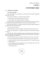
3. BLOCK DIAGRAM
Internal Clock
Timing
XCLK
Sampling Clock
Amp
5-Pole Active
Antialiasing Filter
ANA OUT
MIC
MIC REF
Analog Transceivers
128K Cell
Nonvolatile
Multilevel Storage
Array
Decoders
ANA IN
PreAmp
5-Pole Active
Smoothing Filter
SP +
Amp
SP -
Automatic
Gain Control
(AGC)
AGC
Power Conditioning
VCCA
VSSA VSSD VCCD
Device Control
Address Buffers
A0 A1 A2 A3 A4 A5 A6 A7
-3-
REC
PLAYE PLAYL RECLED
Publication Release Date: March 2004
Revision 1.0
ISD1400 SERIES
4. TABLE OF CONTENTS
1. GENERAL DESCRIPTION.................................................................................................................. 2
2. FEATURES ......................................................................................................................................... 2
3. BLOCK DIAGRAM .............................................................................................................................. 3
4. TABLE OF CONTENTS ...................................................................................................................... 4
5. PIN CONFIGURATION ....................................................................................................................... 5
6. PIN DESCRIPTION ............................................................................................................................. 6
7. FUNCTIONAL DESCRIPTION.......................................................................................................... 10
7.1. Detailed Description.................................................................................................................... 10
7.2. Operational Modes ..................................................................................................................... 11
7.2.1. Operational Modes Description............................................................................................ 11
8. TIMING DIAGRAMS.......................................................................................................................... 13
9. ABSOLUTE MAXIMUM RATINGS.................................................................................................... 14
9.1 Operating Conditions ................................................................................................................... 15
10. ELECTRICAL CHARACTERISTICS ............................................................................................... 16
10.1. Parameters For Packaged Parts .............................................................................................. 16
10.1.1. Typical Parameter Variation with Voltage and Temperature ............................................. 19
10.2. Parameters For DIE.................................................................................................................. 20
10.2.1. Typical Parameter Variation with Voltage and Temperature ............................................. 23
11. TYPICAL APPLICATION CIRCUIT ................................................................................................. 24
12. PACKAGE DRAWING AND DIMENSIONS .................................................................................... 27
12.1. 28-Lead 300 mil Plastic Small Outline IC (SOIC)..................................................................... 27
12.2. 28-Lead 600 mil Plastic Dual Inline Package (PDIP) ............................................................... 28
12.3. Die Physical Layout [1]............................................................................................................... 29
13. ORDERING INFORMATION........................................................................................................... 31
14. VERSION HISTORY ....................................................................................................................... 32
-4-
ISD1400 SERIES
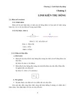
5. PIN CONFIGURATION
A0
1
28
VCCD
A1
2
27
REC
A2
3
26
XCLK
A3
4
25
RECLED
A4
5
24
PLAYE
A5
6
23
PLAYL
NC
7
22
NC
NC
8
21
ANA OUT
A6
9
20
ANA IN
A7
10
19
AGC
NC
11
18
MIC REF
VSSD
12
17
MIC
VSSA
13
16
VCCA
SP +
14
15
SP-
SOIC / PDIP
Note:
NC means must be No connect
-5-
Publication Release Date: March 2004
Revision 1.0
ISD1400 SERIES
6. PIN DESCRIPTION
PIN NAME
PIN NO
FUNCTION
A0-A7
1-6, 9, 10
Address Inputs: The address inputs have two functions,
depending on the level of the two Most Significant Bits (MSB)
of the address.
If either or both of the two MSBs are LOW, the inputs are all
interpreted as address bits and are used as the start address
for the current record or playback cycle. The address pins are
inputs only and do not output internal address information as
the operation progresses. Address inputs are latched by the
falling edge of PLAYE , PLAYL , or REC .
If both A6 & A7 are HIGH, then the device is in special
operational modes. Please refer to operational modes section
for details.
NC
7, 8, 11, 22
VSSD, VSSA
12, 13
Ground: Similar to VCCA and VCCD, the analog and digital
circuits internal to the ISD1400 series use separate ground
buses to minimize noise. These pins should be tied together
as close as possible to the device.
SP+, SP-
14, 15
Speaker Outputs: The SP+ and SP- pins provide direct drive
for loudspeakers with impedances as low as 16 Ω. A single
output may be used, but, for direct-drive loudspeakers, the
two opposite-polarity outputs provide an improvement in
output power of up to four times over a single-ended
connection. Forthermore, when SP+ and SP- are used, a
speakercoupling capacitor is not required. A single-ended
connection will require an AC-coupling capacitor between the
SP pin and the speaker. The speaker outputs are in a highimpedance state during a record cycle, and held at VSSA
during power down.
VCCA, VCCD
16, 28
Supply Voltage: Analog and digital circuits internal to the
ISD1400 series use separate power buses to minimize noise
on the chip. These voltage buses are brought out to separate
pins on the package and should be tied together as close to
the supply as possible. It is important that the power supply
be decoupled as close to the package as possible.
MIC
17
Microphone: The microphone input transfers its signal to the
on-chip preamplifier. An on-chip Automatic Gain Control
(AGC) circuit controls the gain of this preamplifier from –15 to
24dB. An external microphone should be AC coupled to this
pin via a series capacitor. The capacitor value, together with
the internal 10 KΩ resistance on this pin, determines the lowfrequency cutoff for the ISD1400 series passband. See
Winbond’s Application Information for additional information
on low-frequency cutoff calculation.
NC: No Connect
-6-
ISD1400 SERIES
PIN NAME
PIN NO
FUNCTION
MIC REF
18
Microphone Reference: The MIC REF input is the inverting
input to the microphone preamplifier. This provides a noisecanceling or common-mode rejection input to the device
when connected to a differential microphone.
AGC
19
Automatic Gain Control (AGC): The AGC dynamically
adjusts the gain of the preamplifier to compensate for the
wide range of microphone input levels. The AGC allows the
full range of sound, from whispers to loud sounds, to be
recorded with minimal distortion. The “attack” time is
determined by the time constant of a 5 KΩ internal resistance
and an external capacitor (C6 on the schematic of section 11,
Figure 5) connected from the AGC pin to VSSA analog ground.
The “release” time is determined by the time constant of an
external resistor (R5) and an external capacitor (C6)
connected in parallel between the AGC pin and VSSA analog
ground. Nominal values of 470 KΩ and 4.7 µF give
satisfactory results in most cases.
ANA IN
20
Analog Input: The analog input pin transfers its signal to the
chip for recording. For microphone inputs, the ANA OUT pin
should be connected via an external capacitor to the ANA IN
pin. This capacitor value, together with the 3.0 KΩ input
impedance of ANA IN, is selected to give additional cutoff at
the low-frequency end of the voice passband. If the desired
input is derived from a source other than a microphone, the
signal can be fed, capacitively coupled, into the ANA IN pin
directly.
ANA OUT
21
Analog Output: This pin provides the preamplifier output to
the user. The voltage gain of the preamplifier is determined
by the voltage level at the AGC pin.
PLAYL [2]
23
Playback, Level-Activated: When this input signal is held
LOW, a playback cycle is initiated, and playback continues
until PLAYL is pulled HIGH, or an EOM marker is detected.
The device automatically powers down and enters into
standby mode upon completion of a playback cycle.
PLAYE [2]
24
Playback, Edge-Activated: When a LOW-going transition is
input to this pin, a playback cycle begins. Taking PLAYE
HIGH during a playback cycle will not terminate the current
cycle. Playback continues until an EOM is encountered. Upon
completion of a playback cycle, the device automatically
powers down and enters into standby mode.
-7-
Publication Release Date: March 2004
Revision 1.0
ISD1400 SERIES
PIN NAME
PIN NO
FUNCTION
RECLED
25
Record LED: The RECLED output is LOW during a record
cycle. It can be used to drive an LED to indicate a record
cycle is in progress. In addition, RECLED pulses LOW
momentarily when an end-of-message is encountered in a
playback operation.
XCLK
26
External Clock: The input has an internal pull-down device.
The ISD1400 is configured at the factory with an internal
sampling clock frequency that guarantees its minimum
nominal record/playback time. For instance, an ISD1420
operating within specification will be observed to always have
a minimum of 20 seconds of recording time. The sampling
frequency is then maintained to a variation of +2.25 percent
over the commercial temperature and operating voltage
ranges, while still maintaining the minimum specified
recording duration. This will result in some devices having a
few percent more than nominal recording time.
The Internal clock has a +5 percent tolerance over the
industrial temperature and voltage range. A regulated power
supply is recommended for industrial temperature parts. If
greater precision is required, the device can be clocked
through the XCLK pin as follows:
EXTERNAL CLOCK SAMPLE RATES
Sample Rate
Required Clock
ISD1416
Part Number
8.0 kHz
1024 kHz
ISD1420
6.4 kHz
819.2 kHz
These recommended clock rates should not be varied
because the antialiasing and smoothing filters are fixed, and
aliasing problems can occur if the sample rate differs from the
one recommended. The duty cycle on the input clock is not
critical, as the clock is immediately divided by two. If the
XCLK is not used, this input must be connected to
ground.
-8-
ISD1400 SERIES
PIN NAME
PIN NO
FUNCTION
REC
27
Record Input: The REC input is an active-LOW record
signal. The device records whenever REC is LOW. This
signal must remain LOW for the duration of the recording.
REC takes precedence over either playback ( PLAYE or
PLAYL ) signal. If REC is pulled LOW during a playback
cycle, the playback immediately ceases and recording
begins.
A record cycle is completed when REC is pulled HIGH or
the memory space is filled.
And end-of-message marker (EOM) is internally recorded,
enabling a subsequent playback cycle to terminate
appropriately. The device automatically powers down to
standby mode when REC goes HIGH.
Notes:
[1]
The REC signal is debounced for 50 ms on the rising edge to prevent a false retriggering from a pushbutton switch.
[2]
During playback, if either PLAYE or PLAYL is held LOW during EOM or OVF, the device will still
enter into standby mode and the internal oscillator and timing generator will stop. However, the rising
edge of PLAYE and PLAYL are not debounced and any subsequent falling edge (particularly switch
bounce) present on the input pins will initiate another playback.
-9-
Publication Release Date: March 2004
Revision 1.0
ISD1400 SERIES
7. FUNCTIONAL DESCRIPTION
7.1. DETAILED DESCRIPTION
Speech/Sound Quality
The Winbond’s ISD1400 series offer 6.4 and 8.0 kHz sampling frequencies, allowing the user a choice
of speech quality options. The speech samples are stored directly into on-chip non-volatile memory
without the digitization and compression associated with other solutions. Direct analog storage
provides a very true, natural sounding reproduction of voice, music, tones, and sound effects not
available with most solidstate digital solutions.
Duration
To meet end system requirements, the ISD1400 series offer single-chip solutions at 16 and 20
seconds.
TABLE 1: ISD1400 SERIES SUMMARY
Part Number
Duration
(Seconds)
Input Sample
Rate (kHz)
Typical Filter Pass
Band* (kHz)
ISD1416
16
8.0
3.3
ISD1420
20
6.4
2.6
* 3dB roll-off-point
EEPROM Storage
One of the benefits of Winbond’s ChipCorder® technology is the use of on-chip non-volatile memory,
providing zero-power message storage. The message is retained for up to 100 years typically without
power. In addition, the device can be re-recorded typically over 100,000 times.
Basic Operation
The ISD1400 ChipCorder® series are controlled by a single control signal, REC , PLAYE (edgeactivated playback) or PLAYL (level-activated playback). The ISD1400 parts are configured for
simplicity of design in a single/multiple-message application. Using the address lines will allow
multiple message applications.
Automatic Power-Down Mode
At the end of a playback or record cycle, the ISD1400 series automatically return to a low-power
standby mode, consuming typically 0.5 µA. After a playback cycle, the device powers down
automatically at the end of the message. After a record cycle, the device powers down immediately
after REC is pulled to HIGH.
- 10 -
ISD1400 SERIES
Addressing
In addition to providing single message application, the ISD1400 series provide a full addressing
capability.
The ISD1400 series have 160 distinct addressable segments, providing the below resolutions. See
Application Information for ISD1400 address tables.
TABLE 2: DEVICE PLAYBACK/RECORD DURATIONS
Part Number
Minimum Duration (Seconds)
ISD1416
100 ms
ISD1420
125 ms
7.2. OPERATIONAL MODES
The ISD1400 series have several built-in operational modes providing maximum functionality with a
minimal additional components. The operational modes use the address pins, but are mapped to
outside the normal address range. When the two Most Significant Bits (MSBs), A6 and A7, are HIGH,
the remaining address signals are interpreted as mode bits and not as address bits. Therefore,
operational modes and direct addressing are not compatible and cannot be used simultaneously.
There are two important considerations for using operational modes. Firstly, all operations begin
initially at address 0, which is the beginning address. Later operations can begin at other address
locations, depending on the operational mode(s) chosen. In addition, the address pointer is reset to 0
when the device is changed from record to playback but not from playback to record when A4 is HIGH
in Operational Mode.
Secondly, an Operational Mode is executed when any of the control inputs, PLAYE , PLAYL or
REC , goes LOW and the two MSBs are HIGH. This Operational Mode remains in effect until the next
LOW-going control input signal, at which point the current address/mode levels are sampled and
executed.
7.2.1. Operational Modes Description
The Operational Modes can be used in conjunction with a microcontroller, or they can be hardwired to
provide the desired system operation.
A0 – Message Cueing
Message Cueing allows the user to skip through messages, without knowing the actual physical
addresses of each message. Each LOW pulse causes the internal address pointer to skip to the next
message. This mode is used for playback only and typically used with the A4 Operational Mode.
- 11 -
Publication Release Date: March 2004
Revision 1.0
ISD1400 SERIES
A1 – Delete EOM Markers
The A1 Operational Mode allows recording messages sequentially and playback as a single message
with only one EOM set at the end of the final message.
A2 – Unused
A3 – Message Looping
The A3 Operational Mode allows repeating playback a message continuously from the beginning of
the memory. A message can completely fill the ISD1400 device and will loop from beginning to end.
Pulsing PLAYE will start the playback and pulsing PLAYL will end the playback.
A4 – Consecutive Addressing
During normal operation, the address pointer will reset when a message is played through to an
EOM marker. The A4 Operational Mode inhibits the address pointer reset, allowing messages to be
recorded or played back consecutively. When the device is in a static state; i.e., not recording or
playback, momentarily taking this pin LOW will reset the address counter to zero.
A5 – Unsued
TABLE 3: OPERATIONAL MODES
Mode
Function
Typical Use
Jointly Compatible [1]
A0
Message cueing
Fast-forward through messages
A4
A1
Delete EOM markers
Position EOM marker at the end of
the last message
A3, A4
A2
Unused
A3
Looping
Continuous playback from Address 0
A1
A4
Consecutive
addressing
Record/playback multiple consecutive
messages
A0, A1
A5
Unused
1
Additional Operational Modes can be used simultaneously with the given mode.
- 12 -
ISD1400 SERIES
8. TIMING DIAGRAMS
TREC
TREC
REC
TLED1
TLED2
RECLED
THOLD
TSET
THOLD
TSET
A0-A7
MIC
ANA IN
TRPUD
TRPDD
FIGURE 1: RECORD
(1)
REC
TPLAY
PLAYL
PLAYE
TSET
THOLD
THOLD
TSET
TSET
THOLD
A0-A7
SP+/TPPUD
RECLED
TPPDD
TPPDD
TPPUD
(2)
TEOM
TEOM
1. REC must be HIGH for the entire duration of a playback cycle.
2. RECLED funstions as an EOM playback.
FIGURE 2: PLAYBACK
- 13 -
Publication Release Date: March 2004
Revision 1.0
ISD1400 SERIES
9. ABSOLUTE MAXIMUM RATINGS2
TABLE 4: ABSOLUTE MAXIMUM RATINGS (PACKAGED PARTS)
CONDITIONS
VALUES
Junction temperature
150ºC
Storage temperature range
-65ºC to +150ºC
Voltage applied to any pin
(VSS – 0.3V) to (VCC + 0.3V)
Voltage applied to any pin (Input current limited to ±20 mA)
(VSS – 1.0V) to (VCC + 1.0V)
Lead temperature (Soldering – 10sec)
300ºC
VCC – VSS
-0.3V to +7.0V
TABLE 5: ABSOLUTE MAXIMUM RATINGS (DIE)
CONDITIONS
VALUES
Junction temperature
150ºC
Storage temperature range
-65ºC to +150ºC
Voltage applied to any pad
(VSS – 0.3V) to (VCC + 0.3V)
Voltage applied to any pad (Input current limited to ±20mA)
(VSS – 1.0V) to (VCC + 1.0V)
Lead Temperature (soldering 10 seconds)
330º C
VCC – VSS
-0.3V to +7.0V
2
Stresses above those listed may cause permanent damage to the device. Exposure to the absolute maximum
ratings may affect device reliability and performance. Functional operation is not implied at these conditions.
- 14 -
ISD1400 SERIES
9.1 OPERATING CONDITIONS
TABLE 6: OPERATING CONDITIONS (PACKAGED PARTS)
CONDITIONS
VALUES
Commercial operating temperature range (Case temperature)
0ºC to +70ºC
Industrial operating temperature (Case temperature)
-40ºC to +85ºC
Supply voltage (VCC)
Ground voltage (VSS)
[1]
+4.5V to +5.5V
[2]
0V
TABLE 7: OPERATING CONDITIONS (DIE)
CONDITIONS
VALUES
Commercial operating temperature range
Supply voltage (VCC)
Ground voltage (VSS)
[1]
VCC = VCCA = VCCD
[2]
VSS = VSSA = VSSD
0ºC to +50ºC
[1]
+4.5V to +6.5V
[2]
0V
- 15 -
Publication Release Date: March 2004
Revision 1.0
ISD1400 SERIES
10. ELECTRICAL CHARACTERISTICS
10.1. PARAMETERS FOR PACKAGED PARTS
TABLE 8: DC PARAMETERS
PARAMETERS
SYMBOLS
MIN[2]
TYP[1]
Input Low Voltage
VIL
Input High Voltage
VIH
Output Low Voltage
VOL
Output High Voltage
VOH
VCC Current (Operating)
ICC
15
VCC Current (Standby)
ISB
0.5
Input Leakage Current
MAX[2]
UNITS
0.8
V
2.4
CONDITIONS
V
0.4
V
IOL = 4.0 mA
V
IOH = -1.6 mA
30
mA
VCC = 5.5V[3],
REXT = ∞
10
µA
[3] [4]
IIL
+1
µA
Input Current HIGH w/Pull
Down
IILPD
130
µA
Force VCC [5]
Output Load Impedance
REXT
16
Ω
Speaker Load
Preamp IN Input
Resistance
RMIC
4
9
17
KΩ
ANA IN Input Resistance
RANA IN
2.5
3
5
KΩ
Preamp Gain 1
APRE1
20
23
26
dB
AGC = 0.0V
Preamp Gain 2
APRE2
-45
-15
dB
AGC = 2.5V
ANA IN to SP+/- Gain
AARP
20
22
25
dB
AGC Output Resistance
RAGC
2.5
5
9.5
KΩ
Preamp Out Source
IPREH
-2
mA
@ VOUT = 1.0V
Preamp In Sink
IPREL
0.5
mA
@ VOUT = 2.0V
2.4
Pins 17, 18
[1] Typical values @ TA = 25º and 5.0V.
[2] All Min/Max limits are guaranteed by Winbond via electronical testing or characterization. Not all
specifications are 100 percent tested.
[3] VCCA and VCCD connected together.
[4]
REC , PLAYL , and PLAYE must be at VCCD.
[5] XCLK pin .
- 16 -
ISD1400 SERIES
TABLE 9: AC PARAMETERS
CHARACTERISTICS
Sampling Frequency
SYMBOLS
MIN[2]
TYP[1]
FS
ISD1416
MAX[2]
UNITS
8.0
6.4
kHz
[5]
kHz
[5]
ISD1420
Filter Pass Band
CONDITIONS
FCF
ISD1416
3.3
kHz
3 dB Roll-Off Point[3][6]
ISD1420
2.6
kHz
3 dB Roll-Off Point[3][6]
Record Duration
TREC
ISD1416
16
sec
ISD1420
20
sec
ISD1416
16
sec
[5]
ISD1420
20
sec
[5]
Playback Duration
TPLAY
RECLED ON Delay
TLED1
RECLED OFF Delay
TLED2
ISD1416
5
30
40
38.9
48.6
msec
95
110
msec
msec
ISD1420
Address Setup Time
TSET
300
nsec
Address Hold Time
THOLD
0
nsec
Record Power-Up Delay
TRPUD
ISD1416
26
msec
ISD1420
32
msec
ISD1416
26
msec
ISD1420
32
msec
ISD1416
26
msec
ISD1420
32
msec
6.5
8.1
msec
Record Power-Down Delay
Play Power-Up Delay
Play Power-Down Delay
TRPDD
TPPUD
TPPDD
ISD1416
ISD1420
msec
- 17 -
Publication Release Date: March 2004
Revision 1.0
ISD1400 SERIES
CHARACTERISTICS
EOM Pulse Width
SYMBOLS
MIN[2]
TYP[1]
MAX[2]
UNITS
CONDITIONS
TEOM
ISD1416
ISD1420
12.5
msec
15.625
msec
Total Harmonic Distortion
THD
1
Speaker Output Power
POUT
12.2
Voltage Across Speaker Pins
VOUT
1.25
MIC Input Voltage
ANA IN Input Voltage
3
%
@ 1 kHz
mW
REXT = 16 Ω
2.5
V p-p
REXT = 600 Ω
VIN1
20
mV
Peak-to-Peak[5]
VIN2
50
mV
Peak-to-Peak
Notes:
[1] Typical values @ TA = 25º and 5.0V.
[2] All Min/Max limits are guaranteed by Winbond via electronical testing or characterization. Not all specifications are
100 percent tested.
[3] Low-frequency cutoff depends upon the value of external capacitors (see Pin Descriptions)
[4] With 5.1 K Ω series resistor at ANA IN.
[5] Sampling Frequency and playback duration can vary as much as +2.25 percent over the commercial temperature
and voltage rangs. It may vary as much as +5 percent over the industrial temperature and voltage ranges. All
devices will meet the maximum sampling frequency and minimum playback duration parameters. For greater
stability, an external clock can be utilized (see Pin Descriptions)
[6] Filter specification applies to the anti-aliasing filter and the smoothing filter. Typical Parameter Variation with
Voltage and Temperature. This parameter is not checked during production testing and may vary due to process
variations and other factors. Therefore, the customer should not rely upon this value for testing purposes.
- 18 -
ISD1400 SERIES
10.1.1. Typical Parameter Variation with Voltage and Temperature
Chart 3: Standby Current (ISB)
0.30
12
Standby Current (mA)
Operating Current (mA)
14
Chart 1: Record Mode Operating
Current (ICC)
10
8
6
4
2
0
0.25
0.20
0.15
0.10
0
-40
25
70
85
-40
Temperature (C)
5.5 Volts
4.5 Volts
5.5 Volts
Chart 2: Total Harmonic Distortion
70
85
4.5 Volts
Chart 4: Oscillator Stability
0.5
1.5
0.4
Percent Change (%)
Percent Distortion (%)
25
Temperature (C)
0.3
0.2
0.1
0
1.0
0.5
0
-0.5
-1.0
-1.5
-2.0
-40
25
70
85
-40
Temperature (C)
5.5 Volts
25
70
85
Temperature (C)
4.5 Volts
5.5 Volts
- 19 -
4.5 Volts
Publication Release Date: March 2004
Revision 1.0
ISD1400 SERIES
10.2. PARAMETERS FOR DIE
TABLE 10: DC PARAMETERS
PARAMETERS
SYMBOLS
MIN[2]
TYP[1]
Input Low Voltage
VIL
Input High Voltage
VIH
Output Low Voltage
VOL
Output High Voltage
VOH
VCC Current (Operating)
ICC
15
VCC Current (Standby)
ISB
0.5
Input Leakage Current
MAX[2]
UNITS
0.8
V
2.4
CONDITIONS
V
0.4
V
IOL = 4.0 mA
V
IOH = -1.6 mA
30
mA
VCC = 5.5V[3],
REXT = ∞
10
µA
[3] [4]
IIL
+1
µA
Input Current HIGH w/Pull
Down
IILPD
130
µA
Force VCC [5]
Output Load Impedance
REXT
16
Ω
Speaker Load
Preamp IN Input
Resistance
RMIC
4
9
17
KΩ
ANA IN Input Resistance
RANA IN
2.5
3
5
KΩ
Preamp Gain 1
APRE1
20
23
26
dB
AGC = 0.0V
Preamp Gain 2
APRE2
-45
-15
dB
AGC = 2.5V
ANA IN to SP+/- Gain
AARP
20
22
25
dB
AGC Output Resistance
RAGC
2.5
5
9.5
KΩ
Preamp Out Source
IPREH
-2
mA
@ VOUT = 1.0V
Preamp In Sink
IPREL
0.5
mA
@ VOUT = 2.0V
2.4
Pads 17,18
[1] Typical values @ TA = 25º and 5.0V.
[2] All Min/Max limits are guaranteed by Winbond via electronical testing or characterization. Not all
specifications are 100 percent tested.
[3] VCCA and VCCD connected together.
[4]
REC , PLAYL , and PLAYE must be at VCCD.
[5] XCLK pin.
- 20 -
ISD1400 SERIES
TABLE 11: AC PARAMETERS
CHARACTERISTICS
Sampling Frequency
SYMBOLS
MIN[2]
TYP[1]
MAX[2]
UNITS
CONDITIONS
FS
ISD1416
8.0
kHz
[5]
ISD1420
6.4
kHz
[5]
ISD1416
3.3
kHz
3 dB Roll-Off Point[3][6]
ISD1420
2.6
kHz
3 dB Roll-Off Point[3][6]
Filter Pass Band
Record Duration
FCF
TREC
ISD1416
16
sec
ISD1420
20
sec
ISD1416
16
sec
ISD1420
20
sec
Playback Duration
TPLAY
RECLED ON Delay
TLED1
RECLED OFF Delay
TLED2
ISD1416
ISD1420
5
msec
30
38.9
95
msec
40
48.6
110
msec
Address Setup Time
TSET
300
nsec
Address Hold Time
THOLD
0
nsec
Power-Up Delay
TRPUD
ISD1416
26
msec
ISD1420
32
msec
ISD1416
26
msec
ISD1420
32
msec
ISD1416
6.5
msec
ISD1420
8.1
msec
ISD1416
6.5
msec
ISD1420
8.1
msec
PD Pulse Width (Record)
PD Pulse Width (Play)
Play Power-Down Delay
TRPUD
TPPUD
TPPDD
- 21 -
Publication Release Date: March 2004
Revision 1.0
ISD1400 SERIES
CHARACTERISTICS
EOM Pulse Width
SYMBOLS
MIN[2]
TYP[1]
MAX[2]
UNITS
CONDITIONS
TEOM
ISD1416
ISD1420
12.5
msec
15.625
msec
Total Harmonic Distortion
THD
1
Speaker Output Power
POUT
12.2
Voltage Across Speaker Pins
VOUT
1.25
MIC Input Voltage
ANA IN Input Voltage
3
%
@ 1 kHz
mW
REXT = 16 Ω[4]
2.5
V p-p
REXT = 600 Ω
VIN1
20
mV
Peak-to-Peak[4]
VIN2
50
mV
Peak-to-Peak
Notes:
[1] Typical values @ TA = 25º and 5.0V.
[2] All Min/Max limits are guaranteed by Winbond via electronical testing or characterization. Not all specifications are
100 percent tested.
[3] Low-frequency cutoff depends upon the value of external capacitors (see Pin Descriptions)
[4] With 5.1 K Ω series resistor at ANA IN.
[5] Sampling Frequency and playback duration can vary as much as +2.25 percent over the commercial temperature
and voltage rangs. It may vary as much as +5 percent over the industrial temperature and voltage ranges. All
devices will meet the maximum sampling frequency and minimum playback duration parameters. For greater
stability, an external clock can be utilized (see Pin Descriptions)
[6] Filter specification applies to the anti-aliasing filter and the smoothing filter. Typical Parameter Variation with
Voltage and Temperature. This parameter is not checked during production testing and may vary due to process
variations and other factors. Therefore, the customer should not rely upon this value for testing purposes.
- 22 -
ISD1400 SERIES
10.2.1. Typical Parameter Variation with Voltage and Temperature
Chart 7: Standby Current (ISB)
0.35
Standby Current (mA)
Operating Current (mA)
15
Chart 5: Record Mode Operating
Current (ICC)
10
5
0
0.30
0.25
0.20
0.15
0.10
0
0
25
50
0
Temperature (C)
6.5 Volts
5.5 Volts
4.5 Volts
6.5 Volts
Chart 6: Total Harmonic Distortion
50
5.5 Volts
4.5 Volts
Chart 8: Oscillator Stability
0.5
0.4
Percent Change (%)
Percent Distortion (%)
25
Temperature (C)
0.3
0.2
0.1
0
2.5
2.0
1.5
1.0
0.5
0
-0.5
-1.0
-1.5
0
25
50
0
Temperature (C)
6.5 Volts
5.5 Volts
25
50
Temperature (C)
4.5 Volts
6.5 Volts
- 23 -
5.5 Volts
4.5 Volts
Publication Release Date: March 2004
Revision 1.0
ISD1400 SERIES
11. TYPICAL APPLICATION CIRCUIT
VCC
D1
REC
LED
C7
0.001
µF
S1
PLAYL
VCCD 28
VCCA 16
VSSD 12
1 A0
2 A1
R6
R7
R8
100 K Ω 100 K Ω 100 K Ω
S2
3 A2
4 A3
5 A4
6 A5
9 A6
SP+ 14
SP- 15
ANA IN 20
ISD1400
ANA OUT 21
24 PLAYE
27 REC
S3
RECORD
25 RECLED
R9
1 KΩ
16 Ω
SPEAKER
VSSA 13
10 A7
23 PLAYL
PLAYE
R1
1KΩ
C2
0.1 µ F
R2
5.1 K Ω
µF
R3
10 KΩ
C4
0.1 µ F
MIC REF 18
C1
220
µF
ELECTRET
MICROPHONE
MIC 17
AGC 19
26 XCLK
R5
470 KΩ
C6
4.7 µ F
FIGURE 5: DESIGN SCHEMATIC
- 24 -
C3
0.1
C5
0.1 µ F
R4
10 KΩ
ISD1400 SERIES
Functional Description Example
The following operating examples demonstrate the functionality of the ISD1400 series.
1. Record a message:
Pulling the REC signal LOW initiates a record cycle from current location. When REC is
held LOW, the recording continues. Until the memory array is filled up or when REC is
pulled HIGH, recording ceases. An EOM marker is written at the end of message. Then the
device will automatically power down.
2. Edge-activated playback:
Pulling the PLAYE signal LOW initiates a playback cycle from the beginning of the message
until the entire message is played. The rising edge of PLAYE has no effect on operation.
When the EOM marker is encountered, the device automatically powers down. A subsequent
falling edge on PLAYE initiates a new playback operation from the beginning of the
message.
3. Level-activated playback:
Holding the PLAYL signal LOW initiates a playback cycle from the beginning of the
message, until PLAYL is pulled HIGH or when the EOM marker is encountered, playback
operation stops and the device automatically powers down.
4. Record (interrupting playback).
The REC signal takes precedence over playback operation. Holding REC LOW initiates a
new record operation from current location, regardless of any current operation in progress.
5.
RECLED operation.
During record, the RECLED output pin provides an active-LOW signal, which can be used to
drive an LED as a “record-in-progress” indicator. It returns to a HIGH state when the REC
pin is pulled HIGH or when the recording is completed due to the memory being filled.
However, during playback, this pin also pulses LOW to indicate an EOM at the end of a
message.
- 25 -
Publication Release Date: March 2004
Revision 1.0