ENC28J60 1
Bạn đang xem bản rút gọn của tài liệu. Xem và tải ngay bản đầy đủ của tài liệu tại đây (1.64 MB, 102 trang )
ENC28J60
Data Sheet
Stand-Alone Ethernet Controller
with SPI™ Interface
2004 Microchip Technology Inc.
Advance Information
DS39662A
Note the following details of the code protection feature on Microchip devices:
•
Microchip products meet the specification contained in their particular Microchip Data Sheet.
•
Microchip believes that its family of products is one of the most secure families of its kind on the market today, when used in the
intended manner and under normal conditions.
•
There are dishonest and possibly illegal methods used to breach the code protection feature. All of these methods, to our
knowledge, require using the Microchip products in a manner outside the operating specifications contained in Microchip’s Data
Sheets. Most likely, the person doing so is engaged in theft of intellectual property.
•
Microchip is willing to work with the customer who is concerned about the integrity of their code.
•
Neither Microchip nor any other semiconductor manufacturer can guarantee the security of their code. Code protection does not
mean that we are guaranteeing the product as “unbreakable.”
Code protection is constantly evolving. We at Microchip are committed to continuously improving the code protection features of our
products. Attempts to break Microchip’s code protection feature may be a violation of the Digital Millennium Copyright Act. If such acts
allow unauthorized access to your software or other copyrighted work, you may have a right to sue for relief under that Act.
Information contained in this publication regarding device
applications and the like is provided only for your convenience
and may be superseded by updates. It is your responsibility to
ensure that your application meets with your specifications.
MICROCHIP MAKES NO REPRESENTATIONS OR WARRANTIES OF ANY KIND WHETHER EXPRESS OR IMPLIED,
WRITTEN OR ORAL, STATUTORY OR OTHERWISE,
RELATED TO THE INFORMATION, INCLUDING BUT NOT
LIMITED TO ITS CONDITION, QUALITY, PERFORMANCE,
MERCHANTABILITY OR FITNESS FOR PURPOSE.
Microchip disclaims all liability arising from this information and
its use. Use of Microchip’s products as critical components in
life support systems is not authorized except with express
written approval by Microchip. No licenses are conveyed,
implicitly or otherwise, under any Microchip intellectual property
rights.
Trademarks
The Microchip name and logo, the Microchip logo, Accuron,
dsPIC, KEELOQ, microID, MPLAB, PIC, PICmicro, PICSTART,
PRO MATE, PowerSmart, rfPIC, and SmartShunt are
registered trademarks of Microchip Technology Incorporated
in the U.S.A. and other countries.
AmpLab, FilterLab, Migratable Memory, MXDEV, MXLAB,
PICMASTER, SEEVAL, SmartSensor and The Embedded
Control Solutions Company are registered trademarks of
Microchip Technology Incorporated in the U.S.A.
Analog-for-the-Digital Age, Application Maestro, dsPICDEM,
dsPICDEM.net, dsPICworks, ECAN, ECONOMONITOR,
FanSense, FlexROM, fuzzyLAB, In-Circuit Serial
Programming, ICSP, ICEPIC, MPASM, MPLIB, MPLINK,
MPSIM, PICkit, PICDEM, PICDEM.net, PICLAB, PICtail,
PowerCal, PowerInfo, PowerMate, PowerTool, rfLAB,
rfPICDEM, Select Mode, Smart Serial, SmartTel and Total
Endurance are trademarks of Microchip Technology
Incorporated in the U.S.A. and other countries.
SQTP is a service mark of Microchip Technology Incorporated
in the U.S.A.
All other trademarks mentioned herein are property of their
respective companies.
© 2004, Microchip Technology Incorporated, Printed in the
U.S.A., All Rights Reserved.
Printed on recycled paper.
Microchip received ISO/TS-16949:2002 quality system certification for
its worldwide headquarters, design and wafer fabrication facilities in
Chandler and Tempe, Arizona and Mountain View, California in
October 2003. The Company’s quality system processes and
procedures are for its PICmicro® 8-bit MCUs, KEELOQ® code hopping
devices, Serial EEPROMs, microperipherals, nonvolatile memory and
analog products. In addition, Microchip’s quality system for the design
and manufacture of development systems is ISO 9001:2000 certified.
DS39662A-page ii
Advance Information
2004 Microchip Technology Inc.
ENC28J60
Stand-Alone Ethernet Controller with SPI™ Interface
Ethernet Controller Features
Operational
•
•
•
•
• Two programmable LED outputs for LINK, TX,
RX, collision and full/half-duplex status
• Seven interrupt sources with two interrupt pins
• 25 MHz clock
• Clock out pin with programmable prescaler
• Operating voltage range of 3.14V to 3.45V
• TTL level inputs
• Temperature range: -40°C to +85°C Industrial,
0°C to +70°C Commercial (SSOP only)
• 28-pin SPDIP, SSOP, SOIC, QFN packages
•
•
•
•
•
IEEE 802.3 compatible Ethernet controller
Integrated MAC and 10BASE-T PHY
Receiver and collision squelch circuit
Supports one 10BASE-T port with automatic
polarity detection and correction
Supports Full and Half-Duplex modes
Programmable automatic retransmit on collision
Programmable padding and CRC generation
Programmable automatic rejection of erroneous
packets
SPI™ Interface with speeds up to 10 Mb/s
Package Types
Buffer
Medium Access Controller (MAC)
Features
• Supports Unicast, Multicast and Broadcast
packets
• Programmable receive packet filtering and
wake-up host on logical AND or OR of the
following:
- Unicast destination address
- Multicast address
- Broadcast address
- Magic Packet™
- Group destination addresses as defined by
64-bit hash table
- Programmable pattern matching of up to
64 bytes at user-defined offset
• Loopback mode
1
2
3
4
5
6
7
8
9
10
11
12
13
14
VCAP
VSS
CLKOUT
INT
WOL
SO
SI
SCK
CS
RESET
VSSRX
TPINTPIN+
RBIAS
28-pin QFN
VDD
28
27
26
25
24
23
22
21
20
19
18
17
16
15
LEDA
LEDB
VDDOSC
OSC2
OSC1
VSSOSC
VSSPLL
VDDPLL
VDDRX
VSSTX
TPOUT+
TPOUTVDDTX
INT
CLKOUT
VSS
VCAP
VDD
LEDA
LEDB
8-Kbyte transmit/receive packet dual port SRAM
Configurable transmit/receive buffer size
Hardware-managed circular receive FIFO
Byte-wide random and sequential access with
auto-increment
• Internal DMA for fast data movement
• Hardware assisted IP checksum calculation
ENC28J60
28-Pin SPDIP, SSOP, SOIC
•
•
•
•
28 27 26 25 24 23 22
WOL
SO
SI
SCK
CS
RESET
VSSRX
1
2
3
4
5
6
7
ENC28J60
21
20
19
18
17
16
15
VDDOSC
OSC2
OSC1
VSSOSC
VSSPLL
VDDPLL
VDDRX
8 9 10 11 12 13 14
2004 Microchip Technology Inc.
TPINTPIN+
RBIAS
VDDTX
• Wave shaping output filter
• Loopback mode
Advance Information
TPOUTTPOUT+
VSSTX
Physical Layer (PHY) Features
DS39662A-page 1
ENC28J60
Table of Contents
1.0 Overview ...................................................................................................................................................................................... 3
2.0 External Connections ................................................................................................................................................................... 5
3.0 Memory Organization ................................................................................................................................................................. 11
4.0 Serial Peripheral Interface (SPI)................................................................................................................................................. 25
5.0 Ethernet Overview ...................................................................................................................................................................... 31
6.0 Initialization................................................................................................................................................................................. 33
7.0 Transmitting and Receiving Packets .......................................................................................................................................... 39
8.0 Receive Filters............................................................................................................................................................................ 47
9.0 Duplex Mode Configuration and Negotiation.............................................................................................................................. 53
10.0 Flow Control ............................................................................................................................................................................... 55
11.0 Reset .......................................................................................................................................................................................... 59
12.0 Interrupts .................................................................................................................................................................................... 65
13.0 Direct Memory Access Controller ............................................................................................................................................... 75
14.0 Power-Down ............................................................................................................................................................................... 77
15.0 Built-in Self-Test Controller ........................................................................................................................................................ 79
16.0 Electrical Characteristics ............................................................................................................................................................ 83
17.0 Packaging Information................................................................................................................................................................ 89
Index .................................................................................................................................................................................................... 95
On-Line Support................................................................................................................................................................................... 97
Systems Information and Upgrade Hot Line ........................................................................................................................................ 97
Reader Response ................................................................................................................................................................................ 98
Product Identification System............................................................................................................................................................... 99
TO OUR VALUED CUSTOMERS
It is our intention to provide our valued customers with the best documentation possible to ensure successful use of your Microchip
products. To this end, we will continue to improve our publications to better suit your needs. Our publications will be refined and
enhanced as new volumes and updates are introduced.
If you have any questions or comments regarding this publication, please contact the Marketing Communications Department via
E-mail at or fax the Reader Response Form in the back of this data sheet to (480) 792-4150. We
welcome your feedback.
Most Current Data Sheet
To obtain the most up-to-date version of this data sheet, please register at our Worldwide Web site at:
You can determine the version of a data sheet by examining its literature number found on the bottom outside corner of any page.
The last character of the literature number is the version number, (e.g., DS30000A is version A of document DS30000).
Errata
An errata sheet, describing minor operational differences from the data sheet and recommended workarounds, may exist for current
devices. As device/documentation issues become known to us, we will publish an errata sheet. The errata will specify the revision
of silicon and revision of document to which it applies.
To determine if an errata sheet exists for a particular device, please check with one of the following:
• Microchip’s Worldwide Web site;
• Your local Microchip sales office (see last page)
When contacting a sales office, please specify which device, revision of silicon and data sheet (include literature number) you are
using.
Customer Notification System
Register on our web site at www.microchip.com to receive the most current information on all of our products.
DS39662A-page 2
Advance Information
2004 Microchip Technology Inc.
ENC28J60
1.0
OVERVIEW
The ENC28J60 consists of seven major functional
blocks:
The ENC28J60 is a stand-alone Ethernet controller
with an industry standard Serial Peripheral Interface
(SPI™). It is designed to serve as an Ethernet network
interface for any controller equipped with SPI.
The ENC28J60 meets all of the IEEE 802.3 specifications. It incorporates a number of packet filtering
schemes to limit incoming packets. It also provides an
internal DMA module for fast data throughput and hardware assisted IP checksum calculations. Communication with the host controller is implemented via two
interrupt pins and the SPI, with data rates of up to
10 Mb/s. Two dedicated pins are used for LED link and
network activity indication.
A simple block diagram of the ENC28J60 is shown in
Figure 1-1. A typical application circuit using the device
is shown in Figure 1-2. With the ENC28J60, two pulse
transformers and a few passive components are all that
is required to connect a microcontroller to a 10 Mbps
Ethernet network.
FIGURE 1-1:
1.
An SPI interface that serves as a communication channel between the host controller and the
ENC28J60.
Control Registers which are used to control and
monitor the ENC28J60.
A dual port RAM buffer for received and
transmitted data packets.
An arbiter to control the access to the RAM
buffer when requests are made from DMA,
transmit and receive blocks.
The bus interface that interprets data and
commands received via the SPI interface.
The MAC (Medium Access Control) module that
implements IEEE 802.3 compliant MAC logic.
The PHY (Physical Layer) module that encodes
and decodes the analog data that is present on
the twisted pair interface.
2.
3.
4.
5.
6.
7.
The device also contains other support blocks, such as
the oscillator, on-chip voltage regulator, level translators
to provide 5V tolerant I/Os and system control logic.
ENC28J60 BLOCK DIAGRAM
LEDA
Buffer
LEDB
RX
8 Kbytes
Dual Port RAM
MAC
RXBM
TPOUT+
RXF (Filter)
CLKOUT
Control
Registers
TX
RMII
Interface
ch0
Arbiter
ch0
ch1
DMA &
IP Checksum
PHY
TPOUT-
TPIN+
TX
ch1
RX
TXBM
TPIN-
INT
WOL
Flow Control
Bus Interface
MIIM
Interface
RBIAS
Host Interface
CS(1)
SI(1)
SO
OSC1
SPI
System Control
Power-on
Reset
Voltage
Regulator
25 MHz
Oscillator
OSC2
SCK(1)
RESET(1)
Note 1:
VCAP
These pins are 5V tolerant.
2004 Microchip Technology Inc.
Advance Information
DS39662A-page 3
ENC28J60
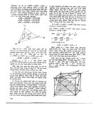
FIGURE 1-2:
TYPICAL ENC28J60-BASED INTERFACE
MCU
ENC28J60
TPIN+/-
CS
I/O
SDO
SO
SDI
SCK
SCK
RJ45
TPOUT+/-
SI
TX/RX
Buffer
MAC
ETHERNET
TRANSFORMER
PHY
LEDA
INT, WOL
INTX
LEDB
TABLE 1-1:
PINOUT I/O DESCRIPTIONS
Pin Number
QFN
Pin
Type
Buffer
Type
1
25
P
—
2.5V output from internal regulator. A 10 µF capacitor to VSSTX must be
placed on this pin.
VSS
2
26
P
—
Ground reference.
CLKOUT
3
27
O
—
Programmable clock output pin.(1)
INT
4
28
O
—
INT interrupt output pin.(2)
WOL
5
1
O
—
Wake-up on LAN interrupt out pin.(2)
SO
6
2
O
—
Data out pin for SPI™ interface.(2)
SI
7
3
I
ST
Data in pin for SPI interface.(3)
SCK
8
4
I
ST
Clock in pin for SPI interface.(3)
CS
9
5
I
ST
Chip select input pin for SPI interface.(3,4)
RESET
10
6
I
ST
Active-low device Reset input.(3, 4)
VSSRX
11
7
P
—
Ground reference for PHY RX.
TPIN-
12
8
I
ANA
Differential signal input.
TPIN+
13
9
I
ANA
Differential signal input.
RBIAS
14
10
I
ANA
Bias current pin for PHY. Must be tied to VSSRX through a 2 kΩ, 1% resistor.
VDDTX
15
11
P
—
Positive supply for PHY TX.
TPOUT-
16
12
O
—
Differential signal output.
TPOUT+
17
13
O
—
Differential signal output.
VSSTX
18
14
P
—
Ground reference for PHY TX.
VDDRX
19
15
P
—
Positive 3.3V supply for PHY RX.
VDDPLL
20
16
P
—
Positive 3.3V supply for PHY PLL.
VSSPLL
21
17
P
—
Ground reference for PHY PLL.
VSSOSC
22
18
P
—
Ground reference for oscillator.
OSC1
23
19
I
DIG
OSC2
24
20
O
—
Oscillator output.
VDDOSC
25
21
P
—
Positive 3.3V supply for oscillator.
LEDB
26
22
O
—
LEDB driver pin.(5)
LEDA
27
23
O
—
LEDA driver pin.(5)
28
24
P
—
Positive 3.3V supply.
Pin Name
SPDIP,
SOIC, SSOP
VCAP
VDD
Legend:
Note 1:
2:
3:
4:
5:
Description
Oscillator input.
I = Input, O = Output, P = Power, DIG = Digital input, ANA = Analog signal input, ST = Schmitt Trigger
Pins have a maximum current capacity of 8 mA.
Pins have a maximum current capacity of 4 mA.
Pins are 5V tolerant.
Pins have an internal weak pull-up to VDD.
Pins have a maximum current capacity of 12 mA.
DS39662A-page 4
Advance Information
2004 Microchip Technology Inc.
ENC28J60
2.0
EXTERNAL CONNECTIONS
2.1
Oscillator
The ENC28J60 is designed to operate at 25 MHz with
a crystal connected to the OSC1 and OSC2 pins. The
ENC28J60 design requires the use of a parallel cut
crystal. Use of a series cut crystal may give a frequency
out of the crystal manufacturer specifications. A typical
oscillator circuit is shown in Figure 2-1.
The ENC28J60 may also be driven by an external clock
source connected to the OSC1 pin as shown in
Figure 2-2.
FIGURE 2-1:
CRYSTAL OSCILLATOR
OPERATION
2.2
Oscillator Start-up Timer
The ENC28J60 contains an Oscillator Start-up Timer
(OST) to ensure that the oscillator and integrated PHY
have stabilized before use. The OST does not expire
until 7500 OSC1 clock cycles (300 µs) pass after
Power-on Reset or wake-up from Power-Down mode
occurs. During the delay, all Ethernet registers and
buffer memory may still be read and written to through
the SPI bus. However, software should not attempt to
transmit any packets (set ECON1.TXRTS), enable
reception of packets (set ECON1.RXEN) or access any
MAC, MII or PHY registers during this period.
When the OST expires, the CLKRDY bit in the ESTAT
register will be set. The application software should poll
this bit as necessary to determine when normal device
operation can begin.
Note:
ENC28J60
OSC1
C1
To Internal Logic
XTAL
After a Power-on Reset, or the ENC28J60
is removed from Power-Down mode, the
CLKRDY bit must be polled before
transmitting packets, enabling packet
reception or accessing any MAC, MII or
PHY registers.
RF(2)
RS(1)
OSC2
C2
Note 1:
A series resistor, RS, may be required for AT
strip cut crystals.
2:
The feedback resistor, RF , is typically in the
range of 2 to 10 MΩ.
FIGURE 2-2:
EXTERNAL CLOCK
SOURCE(1)
ENC28J60
3.3V Clock from
External System
Open(2)
Note 1:
2:
OSC1
OSC2
Duty cycle restrictions must be observed.
A resistor to ground may be used to reduce
system noise. This may increase system
current.
2004 Microchip Technology Inc.
Advance Information
DS39662A-page 5
ENC28J60
2.3
CLKOUT Pin
The clock out pin is provided to the system designer for
use as the host controller clock or as a clock source for
other devices in the system. The CLKOUT has an
internal prescaler which can divide the output by 1, 2,
3, 4 or 8. The CLKOUT function is enabled and the
prescaler is selected via the ECOCON register
(Register 2-1).
To create a clean clock signal, the CLKOUT pin is held
low for a period when power is first applied. After the
Power-on Reset ends, the OST will begin counting.
When the OST expires, the CLKOUT pin will begin outputting its default frequency of 6.25 MHz (main clock
divided by 4). At any future time that the ENC28J60 is
reset by software or the RESET pin, the CLKOUT function will not be altered (ECOCON will not change
FIGURE 2-3:
The CLKOUT function is designed to ensure that minimum timings are preserved when the CLKOUT pin
function is enabled, disabled or the prescaler value is
changed. No high or low pulses will be outputted which
exceed the frequency specified by the ECOCON
configuration. However, when switching frequencies, a
delay between two and eight OSC1 clock periods will
occur where no clock pulses will be produced (see
Figure 2-3). During this period, CLKOUT will be held
low.
CLKOUT TRANSITION
ECOCON
Changed
REGISTER 2-1:
value). Additionally, Power-Down mode may be
entered and the CLKOUT function will continue to
operate. When Power-Down mode is cancelled, the
OST will be reset but the CLKOUT function will
continue. When the CLKOUT function is disabled
(ECOCON = 0), the CLKOUT pin is driven low.
80 ns to 320 ns Delay
ECOCON: CLOCK OUTPUT CONTROL REGISTER
U-0
U-0
U-0
U-0
U-0
—
—
—
—
—
R/W-1
R/W-0
R/W-0
COCON2 COCON1 COCON0
bit 7
bit 0
bit 7-3
Unimplemented: Read as ‘0’
bit 2-0
COCON2:COCON0: Clock Output Configuration bits
111 = Reserved for factory test. Do not use. Glitch prevention not assured.
110 = Reserved for factory test. Do not use. Glitch prevention not assured.
101 = CLKOUT outputs main clock divided by 8 (3.125 MHz)
100 = CLKOUT outputs main clock divided by 4 (6.25 MHz)
011 = CLKOUT outputs main clock divided by 3 (8.333333 MHz)
010 = CLKOUT outputs main clock divided by 2 (12.5 MHz)
001 = CLKOUT outputs main clock divided by 1 (25 MHz)
000 = CLKOUT is disabled. The pin is driven low.
Legend:
DS39662A-page 6
R = Readable bit
W = Writable bit
U = Unimplemented bit, read as ‘0’
-n = Value at POR
‘1’ = Bit is set
‘0’ = Bit is cleared
Advance Information
x = Bit is unknown
2004 Microchip Technology Inc.
ENC28J60
2.4
Magnetics, Termination and Other
External Components
Some of the digital circuitry in the ENC28J60 operates
at a nominal 2.5V to reduce power consumption. A
2.5V regulator is incorporated internally to generate the
necessary voltage. The only external component
required is a 10 µF capacitor for stability purposes. This
capacitor should be attached from VCAP to ground. The
internal regulator was not designed to drive external
loads.
To complete the Ethernet interface, the ENC28J60
requires several standard components to be installed
externally. These components should be connected as
shown in Figure 2-4.
On the differential receive pins (TPIN+/TPIN-), a
1:1 pulse transformer rated for 10BASE-T operation is
required. On the differential transmit pins
(TPOUT+/TPOUT-), a 1:1 pulse transformer with a
center tap is required. The transformers should be
rated for isolation of 2 kV or more to protect against
static voltages. See Section 16.0 “Electrical Characteristics” for specific transformer requirements. Both
portions additionally require two 50Ω, 1% resistors and
a 0.01 µF capacitor for proper termination.
All power supply pins must be externally connected to
the same 3.3V power source. Similarly, all ground
references should be externally connected to the same
ground node. Each VDD and VSS pin pair should have
a 0.1 µF ceramic bypass capacitor placed as close to
the pins as possible. Relatively high currents are necessary to operate the twisted pair interface, so all wires
should be kept as short as possible and reasonable
wire widths should be used on power wires to reduce
resistive loss.
The internal analog circuitry in the ENC28J60 requires
that an external 2 kΩ, 1% resistor be attached from
RBIAS to ground.
FIGURE 2-4:
EXTERNAL CONNECTIONS
3.3V
TPOUT+
I/O
SCK
SDO
SDI
MCU
CS
SCK
SI
SO
3
1:1 CT
4
5
0.01 µF
50Ω
1%
1:1
6
TPIN-
INT
WOL
7
LEDA
LEDB
RBIAS
10 µF
1:
Ferrite Bead should be rated for at least 100 mA.
2:
Required only if the microcontroller is operating at 5V.
2004 Microchip Technology Inc.
2
0.01 µF
50Ω
1%
50Ω
1%
ENC28J60
VCAP
Note
1
Ferrite
Bead(1)
50Ω
1%
TPIN+
5.0V ← 3.3V
Level
Shift
Logic(2)
INT0
INT1
TPOUT-
RJ-45
Advance Information
2K
1%
8
.001 µF
2kV
DS39662A-page 7
ENC28J60
2.5
I/O Levels
2.6
The ENC28J60 is a 3.3V part; however, it was
designed to be easily integrated into 5V systems. The
SPI CS, SCK and SI inputs, as well as the RESET pin,
are all 5V tolerant. On the other hand, if the host
controller is operated at 5V, it quite likely will not be
within specifications when its SPI and interrupt inputs
are driven by the 3.3V CMOS outputs on the
ENC28J60. A unidirectional level translator would be
necessary.
An economical 74HCT08 (quad AND gate), 74ACT125
(quad 3-state buffer) or many other 5V CMOS chips
with TTL level input buffers may be used to provide the
necessary level shifting. The use of 3-state buffers
permits easy integration into systems which share the
SPI bus with other devices. Figure 2-5 and Figure 2-6
show example translation schemes.
FIGURE 2-5:
MCU
LEVEL SHIFTING USING
AND GATES
ENC28J60
I/O
SCK
LEDB is unique in that the connection of the LED is
automatically read on Reset and determines how to initialize the PHCON1.PDPXMD bit. If the pin sources
current to illuminate the LED, the bit is cleared on
Reset and the PHY defaults to half-duplex operation. If
the pin sinks current to illuminate the LED, the bit is set
on Reset and the PHY defaults to full-duplex operation.
Figure 2-7 shows the two available options. If no LED
is attached to the LEDB pin, the PDPXMD bit will reset
to an indeterminate value.
FIGURE 2-7:
LEDB POLARITY AND
RESET CONFIGURATION
OPTIONS
CS
SI
SI
SO
Full-Duplex Operation:
PDPXMD = 1
+3.3V
CLKOUT
INT0
INT
INT1
WOL
FIGURE 2-6:
The LEDA and LEDB pins support automatic polarity
detection on Reset. The LEDs can be connected such
that the pin must source current to turn the LED on, or
alternately connected such that the pin must sink current to turn the LED on. Upon system Reset, the
ENC28J60 will detect how the LED is connected and
begin driving the LED to the default state configured by
the PHLCON register. If the LED polarity is changed
while the ENC28J60 is operating, the new polarity will
not be detected until the next system Reset occurs.
SCK
SO
OSC1
LED Configuration
LEDB
LEVEL SHIFTING USING
3-STATE BUFFERS
Half-Duplex Operation:
PDPXMD = 0
LEDB
ENC28J60
MCU
I/O
SCK
CS
SCK
SO
SI
SI
SO
OSC1
CLKOUT
INT0
INT
INT1
WOL
DS39662A-page 8
Advance Information
2004 Microchip Technology Inc.
ENC28J60
REGISTER 2-2:
PHLCON: PHY MODULE LED CONTROL REGISTER
R/W-0
R/W-0
R/W-1
R/W-1
R/W-0
R/W-1
R/W-0
R/W-0
r
r
r
r
LACFG3
LACFG2
LACFG1
LACFG0
bit 15
bit 15-12
bit 8
R/W-0
R/W-0
R/W-1
R/W-0
R/W-0
R/W-0
R/W-1
R/W-x
LBCFG3
LBCFG2
LBCFG1
LBCFG0
LFRQ1
LFRQ0
STRCH
r
bit 7
Reserved: Write as ‘0’
bit 0
bit 11-8
LACFG3:LACFG0: LEDA Configuration bits
0000 = Reserved
0001 = Display transmit activity (stretchable)
0010 = Display receive activity (stretchable)
0011 = Display collision activity (stretchable)
0100 = Display link status
0101 = Display duplex status
0110 = Reserved
0111 = Display transmit and receive activity (stretchable)
1000 = On
1001 = Off
1010 = Blink fast
1011 = Blink slow
1100 = Display link status and receive activity (always stretched)
1101 = Display link status and transmit/receive activity (always stretched)
1110 = Display duplex status and collision activity (always stretched)
1111 = Reserved
bit 7-4
LBCFG3:LBCFG0: LEDB Configuration bits
0000 = Reserved
0001 = Display transmit activity (stretchable)
0010 = Display receive activity (stretchable)
0011 = Display collision activity (stretchable)
0100 = Display link status
0101 = Display duplex status
0110 = Reserved
0111 = Display transmit and receive activity (stretchable)
1000 = On
1001 = Off
1010 = Blink fast
1011 = Blink slow
1100 = Display link status and receive activity (always stretched)
1101 = Display link status and transmit/receive activity (always stretched)
1110 = Display duplex status and collision activity (always stretched)
1111 = Reserved
bit 3-2
LFRQ1:LFRQ0: LED Pulse Stretch Time Configuration bits
11 = Reserved
10 = Stretch LED events to approximately 139 ms
01 = Stretch LED events to approximately 73 ms
00 = Stretch LED events to approximately 40 ms
bit 1
STRCH: LED Pulse Stretching Enable bit
1 = Stretchable LED events will cause lengthened LED pulses based on the LFRQ configuration
0 = Stretchable LED events will only be displayed while they are occurring
bit 0
Reserved: Write as ‘0’
Legend:
R = Readable bit
W = Writable bit
r = Reserved bit
-n = Value at POR
‘1’ = Bit is set
‘0’ = Bit is cleared
2004 Microchip Technology Inc.
Advance Information
x = Bit is unknown
DS39662A-page 9
ENC28J60
NOTES:
DS39662A-page 10
Advance Information
2004 Microchip Technology Inc.
ENC28J60
3.0
MEMORY ORGANIZATION
All memory in the ENC28J60 is implemented as static
RAM. There are three types of memory in the
ENC28J60:
• Control Registers
• Ethernet Buffer
• PHY Registers
The control registers’ memory contains Control
Registers (CRs). These are used for configuration,
control and status retrieval of the ENC28J60. The
Control Registers are directly read and written to by the
SPI interface.
The Ethernet buffer contains transmit and receive
memory used by the Ethernet controller in a single
memory space. The sizes of the memory areas are
programmable by the host controller using the SPI
interface. The Ethernet buffer memory can only be
accessed via the read buffer memory and write buffer
memory SPI commands (see Section 4.2.2 “Read
Buffer Memory Command” and Section 4.2.4 “Write
Buffer Memory Command”).
The PHY registers are used for configuration, control and
status retrieval of the PHY module. The registers are not
directly accessible through the SPI interface; they can
only be accessed through the Media Independent
Interface (MII) implemented in the MAC.
Figure 3-1 shows the data memory organization for the
ENC28J60.
FIGURE 3-1:
ENC28J60 MEMORY ORGANIZATION
ECON1<1:0>
Control Registers
Ethernet Buffer
00h
0000h
Buffer Pointers in Bank 0
= 00
Bank 0
19h
1Ah
1Fh
00h
Common
Registers
= 01
Bank 1
19h
1Ah
1Fh
00h
Common
Registers
= 10
Bank 2
19h
1Ah
1Fh
00h
Common
Registers
= 11
Bank 3
19h
1Ah
1Fh
Note:
1FFFh
PHY Registers
Common
Registers
00h
1Fh
Memory areas are not shown to scale. The size of the control memory space has been scaled to show detail.
2004 Microchip Technology Inc.
Advance Information
DS39662A-page 11
ENC28J60
3.1
Control Registers
Some of the available addresses are unimplemented.
Any attempts to write to these locations are ignored
while reads return ‘0’s. The register at address 1Ah in
each bank is reserved; read and write operations
should not be performed on this register. All other
reserved registers may be read, but their contents must
not be changed. When reading and writing to registers
which contain reserved bits, any rules stated in the
register definition should be observed.
The Control Registers provide the main interface
between the host controller and the on-chip Ethernet
controller logic. Writing to these registers controls the
operation of the interface, while reading the registers
allows the host controller to monitor operations.
The Control Register memory is partitioned into four
banks, selectable by the bank select bits
BSEL1:BSEL0 in the ECON1 register. Each bank is
32 bytes long and addressed by a 5-bit address value.
Control registers for the ENC28J60 are generically
grouped as ETH, MAC and MII registers. Register
names starting with “E” belong to the ETH group.
Similarly, registers names starting with “MA” belong to
the MAC group and registers prefixed with “MI” belong
to the MII group.
The last five locations (1Bh to 1Fh) of all banks point to a
common set of registers: EIE, EIR, ESTAT, ECON2 and
ECON1. These are key registers used in controlling and
monitoring the operation of the device. Their common
mapping allows easy access without switching the bank.
The ECON1 and ECON2 registers are discussed later in
this section.
TABLE 3-1:
ENC28J60 CONTROL REGISTER MAP
Bank 0
Address
00h
Bank 1
Name
ERDPTL
Address
00h
Bank 2
Name
EHT0
Bank 3
Address
Name
00h
MACON1
Address
00h
Name
MAADR1
01h
ERDPTH
01h
EHT1
01h
MACON2
01h
MAADR0
02h
EWRPTL
02h
EHT2
02h
MACON3
02h
MAADR3
03h
EWRPTH
03h
EHT3
03h
MACON4
03h
MAADR2
04h
ETXSTL
04h
EHT4
04h
MABBIPG
04h
MAADR5
MAADR4
05h
ETXSTH
05h
EHT5
05h
—
05h
06h
ETXNDL
06h
EHT6
06h
MAIPGL
06h
EBSTSD
07h
ETXNDH
07h
EHT7
07h
MAIPGH
07h
EBSTCON
08h
ERXSTL
08h
EPMM0
08h
MACLCON1
08h
EBSTCSL
09h
ERXSTH
09h
EPMM1
09h
MACLCON2
09h
EBSTCSH
0Ah
ERXNDL
0Ah
EPMM2
0Ah
MAMXFLL
0Ah
MISTAT
0Bh
ERXNDH
0Bh
EPMM3
0Bh
MAMXFLH
0Bh
—
0Ch
ERXRDPTL
0Ch
EPMM4
0Ch
Reserved
0Ch
—
0Dh
ERXRDPTH
0Dh
EPMM5
0Dh
MAPHSUP
0Dh
—
0Eh
ERXWRPTL
0Eh
EPMM6
0Eh
Reserved
0Eh
—
0Fh
ERXWRPTH
0Fh
EPMM7
0Fh
—
0Fh
—
10h
EDMASTL
10h
EPMCSL
10h
Reserved
10h
—
11h
EDMASTH
11h
EPMCSH
11h
MICON
11h
—
12h
EDMANDL
12h
—
12h
MICMD
12h
EREVID
13h
EDMANDH
13h
—
13h
—
13h
—
14h
EDMADSTL
14h
EPMOL
14h
MIREGADR
14h
—
15h
EDMADSTH
15h
EPMOH
15h
Reserved
15h
ECOCON
16h
EDMACSL
16h
EWOLIE
16h
MIWRL
16h
Reserved
17h
EDMACSH
17h
EWOLIR
17h
MIWRH
17h
EFLOCON
18h
—
18h
ERXFCON
18h
MIRDL
18h
EPAUSL
19h
—
19h
EPKTCNT
19h
MIRDH
19h
EPAUSH
1Ah
Reserved
1Ah
Reserved
1Ah
Reserved
1Ah
Reserved
1Bh
EIE
1Bh
EIE
1Bh
EIE
1Bh
EIE
1Ch
EIR
1Ch
EIR
1Ch
EIR
1Ch
EIR
1Dh
ESTAT
1Dh
ESTAT
1Dh
ESTAT
1Dh
ESTAT
1Eh
ECON2
1Eh
ECON2
1Eh
ECON2
1Eh
ECON2
1Fh
ECON1
1Fh
ECON1
1Fh
ECON1
1Fh
ECON1
DS39662A-page 12
Advance Information
2004 Microchip Technology Inc.
ENC28J60
TABLE 3-2:
ENC28J60 CONTROL REGISTER SUMMARY
Register Name
Bit 7
Bit 6
Bit 5
Bit 4
Bit 3
Bit 2
Bit 1
Bit 0
Value
on
Reset
Details
on
Page
EIE
INTIE
PKTIE
DMAIE
LINKIE
TXIE
WOLIE
TXERIE
RXERIE
0000 0000
67
EIR
—
PKTIF
DMAIF
LINKIF
TXIF
WOLIF
TXERIF
RXERIF
-000 0000
68
ESTAT
INT
r
r
LATECOL
—
RXBUSY
TXABRT
CLKRDY(1)
0000 -000
66
ECON2
AUTOINC
PKTDEC
PWRSV
—
VRPS
—
—
—
100- 0---
16
ECON1
TXRST
RXRST
DMAST
CSUMEN
TXRTS
RXEN
BSEL1
BSEL0
0000 0000
15
ERDPTL
ERDPTH
EWRPTL
EWRPTH
ETXSTL
ETXSTH
ETXNDL
ETXNDH
ERXSTL
ERXSTH
ERXNDL
ERXNDH
ERXRDPTL
ERXRDPTH
ERXWRPTL
ERXWRPTH
EDMASTL
EDMASTH
EDMANDL
EDMANDH
EDMADSTL
EDMADSTH
EDMACSL
Read Pointer Low Byte ERDPT<7:0>)
—
—
—
Read Pointer High Byte (ERDPT<12:8>)
Write Pointer Low Byte (EWRPT<7:0>)
—
—
—
Write Pointer High Byte (EWRPT<12:8>)
TX Start Low Byte (ETXST<7:0>)
—
—
—
TX Start High Byte (ETXST<12:8>)
TX End Low Byte (ETXND<7:0>)
—
—
—
TX End High Byte (ETXND<12:8>)
RX Start Low Byte (ERXST<7:0>)
—
—
—
RX Start High Byte (ERXST<12:8>)
RX End Low Byte (ERXND<7:0>)
—
—
—
RX End High Byte (ERXND<12:8>)
RX RD Pointer Low Byte (ERXRDPT<7:0>)
—
—
—
RX RD Pointer High Byte (ERXRDPT<12:8>)
RX WR Pointer Low Byte (ERXWRPT<7:0>)
—
—
—
RX WR Pointer High Byte (ERXWRPT<12:8>)
DMA Start Low Byte (EDMAST<7:0>)
—
—
—
DMA Start High Byte (EDMAST<12:8>)
DMA End Low Byte (EDMAND<7:0>)
—
—
—
DMA End High Byte (EDMAND<12:8>)
DMA Destination Low Byte (EDMADST<7:0>)
—
—
—
DMA Destination High Byte (EDMADST<12:8>)
DMA Checksum Low Byte (EDMACS<7:0>)
1111 1010
17
---0 0101
17
0000 0000
17
---0 0000
17
0000 0000
17
---0 0000
17
0000 0000
17
---0 0000
17
1111 1010
17
---0 0101
17
1111 1111
17
---1 1111
17
1111 1010
17
---0 0101
17
0000 0000
17
---0 0000
17
0000 0000
75
---0 0000
75
0000 0000
75
---0 0000
75
0000 0000
75
---0 0000
75
0000 0000
76
EDMACSH
DMA Checksum High Byte (EDMACS<15:8>)
0000 0000
76
EHT0
Hash Table Byte 0 (EHT<7:0>)
0000 0000
52
EHT1
Hash Table Byte 1 (EHT<15:8>)
0000 0000
52
EHT2
Hash Table Byte 2 (EHT<23:16>)
0000 0000
52
EHT3
Hash Table Byte 3 (EHT<31:24>)
0000 0000
52
EHT4
Hash Table Byte 4 (EHT<39:32>)
0000 0000
52
EHT5
Hash Table Byte 5 (EHT<47:40>)
0000 0000
52
EHT6
Hash Table Byte 6 (EHT<55:48>)
0000 0000
52
52
EHT7
Hash Table Byte 7 (EHT<63:56>)
0000 0000
EPMM0
Pattern Match Mask Byte 0 (EPMM<7:0>)
0000 0000
51
EPMM1
Pattern Match Mask Byte 1 (EPMM<15:8>)
0000 0000
51
EPMM2
Pattern Match Mask Byte 2 (EPMM<23:16>)
0000 0000
51
EPMM3
Pattern Match Mask Byte 3 (EPMM<31:24>)
0000 0000
51
EPMM4
Pattern Match Mask Byte 4 (EPMM<39:32>)
0000 0000
51
EPMM5
Pattern Match Mask Byte 5 (EPMM<47:40>)
0000 0000
51
51
EPMM6
Pattern Match Mask Byte 6 (EPMM<55:48>)
0000 0000
EPMM7
Pattern Match Mask Byte 7 (EPMM<63:56>)
0000 0000
51
EPMCSL
Pattern Match Checksum Low Byte (EPMCS<7:0>)
0000 0000
51
Pattern Match Checksum High Byte (EPMCS<15:0>)
0000 0000
51
EPMCSH
Legend:
Note 1:
2:
3:
x = unknown, u = unchanged, — = unimplemented, q = value depends on condition, r = reserved, do not modify.
CLKRDY resets to ‘0’ on Power-on Reset but is unaffected on all other Resets.
EREVID is a read-only register.
ECOCON resets to ‘---- -100’ on Power-on Reset and ‘---- -uuu’ on all other Resets.
2004 Microchip Technology Inc.
Advance Information
DS39662A-page 13
ENC28J60
TABLE 3-2:
Register Name
EPMOL
ENC28J60 CONTROL REGISTER SUMMARY (CONTINUED)
Bit 7
Bit 6
Bit 5
Bit 4
Bit 3
Bit 2
Bit 1
Bit 0
Pattern Match Offset Low Byte (EPMO<7:0>)
0000 0000
51
51
BCWOLIE
00-0 0000
72
BCWOLIF
00-0 0000
73
MCEN
BCEN
1010 0001
48
—
—
—
EWOLIE
UCWOLIE
AWOLIE
—
PMWOLIE
MPWOLIE
HTWOLIE
MCWOLIE
EWOLIR
UCWOLIF
AWOLIF
—
PMWOLIF
MPWOLIF
HTWOLIF
MCWOLIF
UCEN
ANDOR
CRCEN
PMEN
MPEN
HTEN
EPKTCNT
Details
on
Page
---0 0000
EPMOH
ERXFCON
Value
on
Reset
Pattern Match Offset High Byte (EPMO<12:8>)
0000 0000
43
MACON1
—
—
—
LOOPBK
TXPAUS
RXPAUS
PASSALL
MARXEN
---0 0000
34
MACON2
MARST
RNDRST
—
—
MARXRST
RFUNRST
MATXRST
TFUNRST
10-- 0000
61
PADCFG0
TXCRCEN
PHDRLEN
HFRMEN
FRMLNEN
FULDPX
0000 0000
35
BPEN
NOBKOFF
—
—
LONGPRE
PUREPRE
MACON3
Ethernet Packet Count
PADCFG2 PADCFG1
MACON4
—
-000 --00
36
MABBIPG
—
Back-to-Back Inter-Packet Gap (BBIPG<6:0>)
-000 0000
37
MAIPGL
—
Non-Back-to-Back Inter-Packet Gap Low Byte (MAIPGL<6:0>)
-000 0000
34
MAIPGH
—
Non-Back-to-Back Inter-Packet Gap High Byte (MAIPGH<6:0>)
-000 0000
34
MACLCON1
—
—
MACLCON2
—
—
DEFER
—
—
Retransmission Maximum (RETMAX<3:0>)
Collision Window (COLWIN<5:0>)
---- 1111
34
--11 0111
34
MAMXFLL
Maximum Frame Length Low Byte (MAMXFL<7:0>)
0000 0000
34
MAMXFLH
Maximum Frame Length High Byte (MAMXFL<15:8>)
0000 0110
34
MAPHSUP
62
RSTINTFC
—
—
r
RSTRMII
—
—
r
0--1 0--0
MICON
RSTMII
—
—
—
—
—
—
—
0--- ----
21
MICMD
—
—
—
—
—
—
MIISCAN
MIIRD
---- --00
21
—
—
—
MIREGADR
MII Register Address (MIREGADR<4:0>)
---0 0000
19
0000 0000
19
MIWRL
MII Write Data Low Byte (MIWR<7:0>)
MIWRH
MII Write Data High Byte (MIWR<15:8>)
0000 0000
19
MIRDL
MII Read Data Low Byte (MIRD<7:0>)
0000 0000
19
MIRDH
MII Read Data High Byte(MIRD<15:8>)
0000 0000
19
MAADR1
MAC Address Byte 1 (MAADR<15:8>)
0000 0000
34
MAADR0
MAC Address Byte 0 (MAADR<7:0>)
0000 0000
34
MAADR3
MAC Address Byte 3 (MAADR<31:24>)
0000 0000
34
MAADR2
MAC Address Byte 2(MAADR<23:16>)
0000 0000
34
MAADR5
MAC Address Byte 5 (MAADR<48:41>)
0000 0000
34
MAADR4
MAC Address Byte 4 (MAADR<40:32>)
0000 0000
34
EBSTSD
Built-in Self-Test Fill Seed (EBSTSD<7:0>)
0000 0000
80
0000 0000
79
EBSTCON
PSV2
PSV1
PSV0
PSEL
TMSEL1
TMSEL0
TME
BISTST
EBSTCSL
Built-in Self-Test Checksum Low Byte (EBSTCS<7:0>)
0000 0000
80
EBSTCSH
Built-in Self-Test Checksum High Byte (EBSTCS<15:8>)
0000 0000
80
MISTAT
—
—
—
EREVID(2)
—
—
—
ECOCON(3)
—
—
—
—
—
COCON2
COCON1
COCON0
---- -100
6
EFLOCON
—
—
—
—
—
FULDPXS
FCEN1
FCEN0
---- -000
56
—
r
NVALID
SCAN
BUSY
Ethernet Revision ID (EREVID<4:0>)
---- 0000
22
---q qqqq
22
EPAUSL
Pause Timer Value Low Byte (EPAUS<7:0>)
0000 0000
57
EPAUSH
Pause Timer Value High Byte (EPAUS<15:8>)
0001 0000
57
Legend:
Note 1:
2:
3:
x = unknown, u = unchanged, — = unimplemented, q = value depends on condition, r = reserved, do not modify.
CLKRDY resets to ‘0’ on Power-on Reset but is unaffected on all other Resets.
EREVID is a read-only register.
ECOCON resets to ‘---- -100’ on Power-on Reset and ‘---- -uuu’ on all other Resets.
DS39662A-page 14
Advance Information
2004 Microchip Technology Inc.
ENC28J60
3.1.1
ECON1 REGISTER
The ECON1 register, shown in Register 3-1, is used to
control the main functions of the ENC28J60. Receive
enable, transmit request, DMA control and bank select
bits can all be found in ECON1.
REGISTER 3-1:
ECON1: ETHERNET CONTROL REGISTER 1
R/W-0
R/W-0
R/W-0
R/W-0
R/W-0
R/W-0
R/W-0
R/W-0
TXRST
RXRST
DMAST
CSUMEN
TXRTS
RXEN
BSEL1
BSEL0
bit 7
bit 0
bit 7
TXRST: Transmit Logic Reset bit
1 = Transmit logic is held in Reset
0 = Normal operation
bit 6
RXRST: Receive Logic Reset bit
1 = Receive logic is held in Reset
0 = Normal operation
bit 5
DMAST: DMA Start and Busy Status bit
1 = DMA copy or checksum operation is in progress
0 = DMA hardware is Idle
bit 4
CSUMEN: DMA Checksum Enable bit
1 = DMA hardware calculates checksums
0 = DMA hardware copies buffer memory
bit 3
TXRTS: Transmit Request To Send bit
1 = The transmit logic is attempting to transmit a packet
0 = The transmit logic is Idle
bit 2
RXEN: Receive Enable bit
1 = Packets which pass the current filter configuration will be written into the receive buffer
0 = All packets received will be ignored
bit 1-0
BSEL1:BSEL0: Bank Select bits
11 = SPI accesses registers in Bank 3
10 = SPI accesses registers in Bank 2
01 = SPI accesses registers in Bank 1
00 = SPI accesses registers in Bank 0
Legend:
R = Readable bit
W = Writable bit
U = Unimplemented bit, read as ‘0’
-n = Value at POR
‘1’ = Bit is set
‘0’ = Bit is cleared
2004 Microchip Technology Inc.
Advance Information
x = Bit is unknown
DS39662A-page 15
ENC28J60
3.1.2
ECON2 REGISTER
The ECON2 register, shown in Register 3-2, is used to
control other main functions of the ENC28J60.
REGISTER 3-2:
ECON2: ETHERNET CONTROL REGISTER 2
R/W-1
W-0
AUTOINC PKTDEC
R/W-0
U-0
R/W-0
U-0
U-0
U-0
PWRSV
—
VRPS
—
—
—
bit 7
bit 0
bit 7
AUTOINC: Automatic Buffer Pointer Increment Enable bit
1 = Automatically increment ERDPT and EWRPT when the SPI RBM/WBM command is used
0 = Do not automatically change ERDPT and EWRPT after the buffer is accessed
bit 6
PKTDEC: Packet Decrement bit
1 = Decrement the EPKTCNT register by one
0 = Leave EPKTCNT unchanged
bit 5
PWRSV: Power Save Enable bit
1 = MAC, PHY and control logic are in Low-Power Sleep mode
0 = Normal operation
bit 4
Unimplemented: Read as ‘0’
bit 3
VRPS: Voltage Regulator Power Save Enable bit
When PWRSV = 1:
1 = Internal voltage regulator is in Low-Current mode
0 = Internal voltage regulator is in Normal Current mode
When PWRSV = 0:
The bit is ignored; the regulator always outputs as much current as the device requires.
bit 2-0
Unimplemented: Read as ‘0’
Legend:
DS39662A-page 16
R = Readable bit
W = Writable bit
U = Unimplemented bit, read as ‘0’
- n = Value at POR
‘1’ = Bit is set
‘0’ = Bit is cleared
Advance Information
x = Bit is unknown
2004 Microchip Technology Inc.
ENC28J60
3.2
3.2.2
Ethernet Buffer
The Ethernet buffer contains transmit and receive
memory used by the Ethernet controller. The entire
buffer is 8 Kbytes, divided into separate receive and
transmit buffer spaces. The sizes and locations of
transmit and receive memory are fully programmable
by the host controller using the SPI interface.
The relationship of the buffer spaces is shown in
Figure 3-2.
3.2.1
RECEIVE BUFFER
The receive buffer constitutes a circular FIFO buffer
managed by hardware. The register pairs
ERXSTH:ERXSTL and ERXNDH:ERXNDL serve as
pointers to define the buffer’s size and location within
the memory. The byte pointed to by ERXST and the
byte pointed to by ERXND are both included in the
FIFO buffer.
As bytes of data are received from the Ethernet
interface, they are written into the receive buffer
sequentially. However, after the memory pointed to by
ERXND is written to, the hardware will automatically
write the next byte of received data to the memory
pointed to by ERXST. As a result, the receive hardware
will never write outside the boundaries of the FIFO.
The host controller may program the ERXST and
ERXND pointers when the receive logic is not enabled.
The pointers must not be modified while the receive
logic is enabled (ECON1.RXEN is set). If desired, the
pointers may span the 1FFFh to 0000h memory
boundary; the hardware will still operate as a FIFO.
The ERXWRPTH:ERXWRPTL registers define a
location within the FIFO where the hardware will write
bytes that it receives. The pointer is read-only and is
automatically updated by the hardware whenever a
new packet is successfully received. The pointer is
useful for determining how much free space is
available within the FIFO.
The ERXRDPT registers define a location within the
FIFO where the receive hardware is forbidden to write
to. In normal operation, the receive hardware will write
data up to, but not including, the memory pointed to by
ERXRDPT. If the FIFO fills up with data and new data
continues to arrive, the hardware will not overwrite the
previously received data. Instead, the new data will be
thrown away and the old data will be preserved. In
order to continuously receive new data, the host controller must periodically advance this pointer whenever
it finishes processing some, or all, of the old received
data.
2004 Microchip Technology Inc.
TRANSMIT BUFFER
Any space within the 8-Kbyte memory, which is not
programmed as part of the receive FIFO buffer, is
considered to be the transmit buffer. The responsibility
of managing where packets are located in the transmit
buffer belongs to the host controller. Whenever the host
controller decides to transmit a packet, the ETXST and
ETXND pointers are programmed with addresses
specifying where, within the transmit buffer, the particular packet to transmit is located. The hardware does
not check that the start and end addresses do not
overlap with the receive buffer. To prevent buffer
corruption, the host controller must make sure to not
transmit a packet while the ETXST and ETXND
pointers are overlapping the receive buffer, or while the
ETXND pointer is too close to the receive buffer. See
Section 7.1 “Transmitting Packets” for more
information.
3.2.3
READING AND WRITING TO
THE BUFFER
The Ethernet buffer contents are accessed from the
host controller though separate read and write pointers
(ERDPT and EWRPT) combined with the read buffer
memory and write buffer memory SPI commands.
While sequentially reading from the receive buffer, a
wrapping condition will occur at the end of the receive
buffer. While sequentially writing to the buffer, no wrapping conditions will occur. See Section 4.2.2 “Read
Buffer Memory Command” and Section 4.2.4 “Write
Buffer Memory Command” for more information.
3.2.4
DMA ACCESS TO THE BUFFER
The integrated DMA controller must read from the buffer
when calculating a checksum and it must read and write
to the buffer when copying memory. The DMA follows
the same wrapping rules that SPI accesses do. While it
sequentially reads, it will be subject to a wrapping condition at the end of the receive buffer. All writes it does will
not be subject to any wrapping conditions. See
Section 13.0 “Direct Memory Access Controller” for
more information.
Advance Information
DS39662A-page 17
ENC28J60
FIGURE 3-2:
ETHERNET BUFFER ORGANIZATION
Transmit Buffer Start
(ETXSTH:ETXSTL)
0000h
Buffer Write Pointer
(EWRPTH:EWRPTL)
Transmit Buffer Data
AAh
(WBM AAh)
Transmit
Transmit Buffer End
(ETXNDH:ETXNDL)
Buffer
Receive Buffer Start
(ERXSTH:ERXSTL)
Receive
Buffer
(Circular FIFO)
Buffer Read Pointer
(ERDPTH:ERDPTL)
Receive Buffer Data
(RBM 55h)
55h
Receive Buffer End
1FFFh
(ERXNDH:ERXNDL)
DS39662A-page 18
Advance Information
2004 Microchip Technology Inc.
ENC28J60
3.3
PHY Registers
To write to a PHY register:
The PHY registers provide configuration and control of
the PHY module, as well as status information about its
operation. All PHY registers are 16 bits in width. There
are a total of 32 PHY addresses; however, only 9 locations are implemented. Writes to unimplemented
locations are ignored and any attempts to read these
locations will return ‘0’. All reserved locations should be
written as ‘0’; their contents should be ignored when
read.
1.
Unlike the ETH, MAC and MII control registers, or the
buffer memory, the PHY registers are not directly
accessible through the SPI control interface. Instead,
access is accomplished through a special set of MAC
control registers that implement a Media Independent
Interface for Management (MIIM). These control registers are referred to as the MII registers. The registers
that control access to the PHY registers are shown in
Register 3-3 and Register 3-4.
The PHY register will be written after the MII operation
completes, which takes 10.24 µs. When the write
operation has completed, the BUSY bit will clear itself.
The host controller should not start any MIISCAN or
MIIRD operations while busy.
3.3.1
READING PHY REGISTERS
When a PHY register is read, the entire 16 bits are
obtained.
2.
3.
3.3.3
2.
3.
4.
5.
Write the address of the PHY register to read
from into the MIREGADR register.
Set the MICMD.MIIRD bit. The read operation
begins and the MISTAT.BUSY bit is set.
Wait 10.24 µs. Poll the MISTAT.BUSY bit to be
certain that the operation is complete. While
busy, the host controller should not start any
MIISCAN operations or write to the MIWRH
register.
When the MAC has obtained the register
contents, the BUSY bit will clear itself.
Clear the MICMD.MIIRD bit.
Read the desired data from the MIRDL and
MIRDH registers. The order that these bytes are
accessed is unimportant.
3.3.2
WRITING PHY REGISTERS
When a PHY register is written to, the entire 16 bits is
written at once; selective bit writes are not implemented. If it is necessary to reprogram only select bits
in the register, the controller must first read the PHY
register, modify the resulting data and then write the
data back to the PHY register.
2004 Microchip Technology Inc.
SCANNING A PHY REGISTER
The MAC can be configured to perform automatic
back-to-back read operations on a PHY register. This
can significantly reduce the host controller complexity
when periodic status information updates are desired.
To perform the scan operation:
1.
To read from a PHY register:
1.
Write the address of the PHY register to write to
into the MIREGADR register.
Write the lower 8 bits of data to write into the
MIWRL register.
Write the upper 8 bits of data to write into the
MIWRH register. Writing to this register automatically begins the MII transaction, so it must
be written to after MIWRL. The MISTAT.BUSY
bit becomes set.
2.
Write the address of the PHY register to read
from into the MIREGADR register.
Set the MICMD.MIISCAN bit. The scan operation begins and the MISTAT.BUSY bit is set. The
first read operation will complete after 10.24 µs.
Subsequent reads will be done at the same
interval until the operation is cancelled. The
MISTAT.NVALID bit may be polled to determine
when the first read operation is complete.
After setting the MIISCAN bit, the MIRDL and MIRDH
registers will automatically be updated every 10.24 µs.
There is no status information which can be used to
determine when the MIRD registers are updated. Since
the host controller can only read one MII register at a
time through the SPI, it must not be assumed that the
values of MIRDL and MIRDH were read from the PHY
at exactly the same time.
When the MIISCAN operation is in progress, the host
controller must not attempt to write to MIWRH or start
an MIIRD operation. The MIISCAN operation can be
cancelled by clearing the MICMD.MIISCAN bit and
then polling the MISTAT.BUSY bit. New operations may
be started after the BUSY bit is cleared.
Advance Information
DS39662A-page 19
DS39662A-page 20
PHID2
PHCON2
PHSTAT2
PHIE
PHIR
PHLCON
03h
10h
11h
12h
13h
14h
Bit 14
—
PLOOPBK
PFDPX
—
—
—
Bit 12
Bit 13
r
r
r
r
r
—
—
r
FRCLNK
—
r
r
r
TXSTAT
TXDIS
Bit 11
r
PHDPX
PPWRSV
r
r
r
r
r
LSTAT
JABBER
—
r
Bit 10
LACFG3:LACFG0
r
r
RXSTAT COLSTAT
r
PHY Identifier (PID24:PID19) = 000101
PHY Identifier (PID18:PID3) = 0083h
—
PRST
Bit 15
ENC28J60 PHY REGISTER SUMMARY
r
r
r
—
DPXSTAT(1)
r
HDLDIS
r
r
r
—
r
—
—
Bit 6
LBCFG3:LBCFG0
r
r
—
r
—
r
—
Bit 7
Bit 8
PDPXMD(1)
PHY P/N (PPN5:PPN0) = 00h
—
—
Bit 9
r
r
—
r
—
—
Bit 5
PLNKIF
PLNKIE
PLRITY
r
—
—
Bit 4
—
Bit 1
LLSTAT JBSTAT
—
Bit 2
—
—
Bit 0
PGIF
r
—
r
LFRQ1:LFRQ0
r
r
—
r
STRCH
r
PGEIE
—
r
r
r
r
—
r
PHY Revision (PREV3:PREV0) = 00h
—
—
Bit 3
x = unknown, u = unchanged, — = unimplemented, q = value depends on condition, r = reserved, do not modify.
Reset values of the Duplex mode/status bits depend on the connection of the LED to the LEDB pin (see Section 2.6 “LED Configuration” for additional details).
PHID1
02h
Legend:
Note 1:
PHSTAT1
01h
Name
PHCON1
00h
Addr
TABLE 3-3:
Reset Values
0011 0100 0010 001x
xxxx xxxx xx00 00x0
0000 0000 0000 0000
--00 00q- ---0 ----
-000 0000 0000 0000
0001 0100 0000 0000
0000 0000 1000 0011
---1 1--- ---- -00-
00-- 10-q 0--- ----
ENC28J60
Advance Information
2004 Microchip Technology Inc.
ENC28J60
REGISTER 3-3:
MICON: MII CONTROL REGISTER
R/W-0
U-0
U-0
U-0
U-0
U-0
U-0
U-0
RSTMII
—
—
—
—
—
—
—
bit 7
bit 0
bit 7
RSTMII: MII Management Module Reset bit
1 = MII management module held in Reset
0 = Normal operation
bit 6-0
Unimplemented: Read as ‘0’
Legend:
REGISTER 3-4:
R = Readable bit
W = Writable bit
U = Unimplemented bit, read as ‘0’
-n = Value at POR
‘1’ = Bit is set
‘0’ = Bit is cleared
x = Bit is unknown
MICMD: MII COMMAND REGISTER
U-0
U-0
U-0
U-0
U-0
U-0
R/W-0
R/W-0
—
—
—
—
—
—
MIISCAN
MIIRD
bit 7
bit 0
bit 7-2
Unimplemented: Read as ‘0’
bit 1
MIISCAN: MII Scan Enable bit
1 = PHY register at MIREGADR is continously read and the data is placed in MIRD
0 = No MII management scan operation is in progress
bit 0
MIIRD: MII Read Enable bit
1 = PHY register at MIREGADR is read once and the data is placed in MIRD
0 = No MII management read operation is in progress
Legend:
R = Readable bit
W = Writable bit
U = Unimplemented bit, read as ‘0’
-n = Value at POR
‘1’ = Bit is set
‘0’ = Bit is cleared
2004 Microchip Technology Inc.
Advance Information
x = Bit is unknown
DS39662A-page 21
ENC28J60
REGISTER 3-5:
MISTAT: MII STATUS REGISTER
U-0
U-0
U-0
U-0
R-0
R-0
R-0
R-0
—
—
—
—
r
NVALID
SCAN
BUSY
bit 7
bit 0
bit 7-4
Unimplemented: Read as ‘0’
bit 3
Reserved: Maintain ‘0’
bit 1
NVALID: MII Management Read Data Not Valid bit
1 = The contents of MIRD are not valid yet
0 = The MII management read cycle has completed and MIRD has been updated
bit 1
SCAN: MII Management Scan Operation bit
1 = MII management scan operation is in progress
0 = No MII management scan operation is in progress
bit 0
BUSY: MII Management Busy bit
1 = A PHY register is currently being read or written to
0 = The MII management interface is Idle
Legend:
3.3.4
R = Readable bit
r = reserved, maintain as ‘0’ U = Unimplemented bit, read as ‘0’
-n = Value at POR
‘1’ = Bit is set
‘0’ = Bit is cleared
3.3.5
PHSTAT REGISTERS
x = Bit is unknown
PHID1 AND PHID2 REGISTERS
The PHSTAT1 and PHSTAT2 registers contain readonly bits that show the current status of the PHY
module’s operations, particularly the conditions of the
communications link to the rest of the network.
The PHID1 and PHID2 registers are read-only
registers. They hold constant data that help identify the
Ethernet controller and may be useful for debugging
purposes. This includes:
The PHSTAT1 register (Register 3-6) contains the
LLSTAT bit; it clears and latches low if the physical
layer link has gone down since the last read of the
register. Periodic polling by the host controller can be
used to determine exactly when the link fails. It may be
particularly useful if the link change interrupt is not
used.
• The part number of the PHY module
(PPN5:PPN0)
• The revision level of the PHY module
(PREV3:PREV0); and
• The PHY Identifier, as part of Microchip’s
corporate Organizationally Unique Identifier (OUI)
(PID24:PID3)
The PHSTAT1 register also contains a jabber status bit.
An Ethernet controller is said to be “jabbering” if it continuously transmits data without stopping and allowing
other nodes to share the medium. Generally, the jabber
condition indicates that the local controller may be
grossly violating the maximum packet size defined by
the IEEE specification. This bit latches high to indicate
that a jabber condition has occurred since the last read
of the register.
The PHY part number and revision are part of PHID2.
The upper two bytes of the PHY identifier are located in
PHID1, with the remainder in PHID2. The exact
locations within registers are shown in Table 3-3.
Revision information is also stored in EREVID. This is
a read-only control register which contains a 5-bit
identifier for the specific silicon revision level of the
device. Details of this register are shown in Table 3-2.
The PHSTAT2 register (Register 3-7) contains status
bits which report if the PHY module is linked to the
network and whether or not it is transmitting or
receiving.
DS39662A-page 22
Advance Information
2004 Microchip Technology Inc.
ENC28J60
REGISTER 3-6:
PHSTAT1: PHYSICAL LAYER STATUS REGISTER 1
U-0
U-0
U-0
R-1
R-1
U-0
U-0
U-0
—
—
—
PFDPX
PHDPX
—
—
—
bit 15
bit 8
U-0
U-0
U-0
U-0
U-0
R/LL-0
R/LH-0
U-0
—
—
—
—
—
LLSTAT
JBRSTAT
—
bit 7
bit 0
bit 15-13 Unimplemented: Read as ‘0’
bit 12
PFDPX: PHY Full-Duplex Capable bit
1 = PHY is capable of operating at 10 Mbps in Full-Duplex mode (this bit is always set)
bit 11
PHDPX: PHY Half-Duplex Capable bit
1 = PHY is capable of operating at 10 Mbps in Half-Duplex mode (this bit is always set)
bit 10-3
Unimplemented: Read as ‘0’
bit 2
LLSTAT: PHY Latching Link Status bit
1 = Link is up and has been up continously since PHSTAT1 was last read
0 = Link is down or was down for a period since PHSTAT1 was last read
bit 1
JBRSTAT: PHY Latching Jabber Status bit
1 = PHY has detected a transmission meeting the jabber criteria since PHYSTAT1 was last read
0 = PHY has not detected any jabbering transmissions since PHYSTAT1 was last read
bit 0
Unimplemented: Read as ‘0’
Legend:
R = Read-only bit
R/L = Read-only latch bit
U = Unimplemented bit, read as ‘0’
‘1’ = Bit is set on POR
‘0’ = Bit is cleared on POR
LL = Bit latches low
2004 Microchip Technology Inc.
Advance Information
LH = Bit latches high
DS39662A-page 23