Ford diesel TSB 08 26 03 6 0l DIESEL DRIVEABILITY NO START HARD START RUNS ROUGH FUEL INJECTION CONTROL MODULE DIAGNOSIS
Bạn đang xem bản rút gọn của tài liệu. Xem và tải ngay bản đầy đủ của tài liệu tại đây (179.99 KB, 5 trang )
6.0L DIESEL—DRIVEABILITY—NO START, HARD
START, RUNS ROUGH—FUEL INJECTION CONTROL
MODULE DIAGNOSIS
FORD:
2003-2005 Excursion
This article supersedes TSBs 04-18-6 and 07-5-4 to
update the repair sequence, FICM_MPWR check,
symptoms and additional diagnostic information.
ISSUE
Some 2003-2005 Excursion, 2003-2007 F-Super
Duty and 2004-2009 E-Series vehicles equipped
with a 6.0L diesel engine may experience no starts,
hard starts or rough running when cold and may be
accompanied with diagnostic trouble codes (DTCs)
P0611, P1378 and / or all 8 injector circuit codes.
These symptoms may lessen or disappear when the
engine is warm. These conditions may be caused
by the Fuel Injection Control Module (FICM) or
injector spool valve sticking internally during cold
engine operation.
ACTION
Follow the Service Procedure steps to correct the
condition.
SERVICE TIPS
A failed FICM module can cause diagnostic trouble
codes related to injectors even when the injectors
or injector wiring are not at fault. The FICM module
should be checked for proper operation before
evaluating injector operation or wiring issues.
For information: Symptoms of stiction (These
conditions are caused by the injector spool valve
sticking internally during cold engine operation
engine oil temperature) can be improved by using
the lightest possible specified weight oil during
winter months. Refer to the Owner Guide
Information - Diesel Supplement / Maintenance and
Specifications / Engine oil specifications. After
confirming that the appropriate weight oil is being
used, evaluate the injector operation according to
Step 13 of the Service Procedure.
TSB 08-26-3
2003-2007 F-Super Duty
2004-2009 E-350, E-450, E-550
Information On The FICM TEST:
An improperly operating vehicle battery(s) or
charging system can cause additional operating
loads to the internal components of the FICM
module, due to low power supply voltages. Glow
plug operation, vehicle accessories (factory and
non-factory installed), and hot and cold
temperatures can also put additional requirements
on the vehicles electrical, battery and charging
system. This can result in shortened FICM module
component life.
The FICM module contains two major internal
components, the main circuit board and a DC-DC
converter. The DC-DC converter is the device that
amplifies battery voltage to 48 volts (V) to operate
the injectors. Two major test entry conditions listed
below are critical to accurately test the FICM
DC-DC converter:
Engine Oil Temperature (EOT) Less Than 68 °F
(20 °C)
The calibration in the FICM uses a pre-cycle mode
during Key On Engine Off (KOEO) / glow plug
operation. This mode is used to rapidly heat the
injector spool valve and prevent sticking during cold
operation. During this mode, the electrical demand
on the FICM DC-DC converter is near maximum.
L_PWR >= 11.5 V
The target 48 V output of the DC-DC converter is
directly affected by the battery supply voltage, or
B+. This is measured internally to the FICM with
the FICM_VPWR PID. Ensuring both of the above
criteria are met before conducting the FICM_MPWR
test will prevent incorrect readings, misdiagnosis
and replacement of good parts.
NOTE: The information in Technical Service Bulletins is intended for use by trained, professional technicians with the knowledge, tools, and equipment to do
the job properly and safely. It informs these technicians of conditions that may occur on some vehicles, or provides information that could assist in proper
vehicle service. The procedures should not be performed by “do-it-yourselfers”. Do not assume that a condition described affects your car or truck. Contact a
Ford, Lincoln, or Mercury dealership to determine whether the Bulletin applies to your vehicle. Warranty Policy and Extended Service Plan documentation
determine Warranty and/or Extended Service Plan coverage unless stated otherwise in the TSB article.The information in this Technical Service Bulletin
(TSB) was current at the time of printing. Ford Motor Company reserves the right to supercede this information with updates.The most recent information is
available through Ford Motor Company’s on-line technical resources.
Copyright 2008 Ford Motor Company Online Publication Date December 12, 2008
PAGE 1
TSB 08-26-3 (Continued)
SERVICE PROCEDURE
1.
Verify the battery and charging system are
functioning properly. Refer to Workshop Manual
(WSM), Section 414-00 for diagnosis and
repair. If the battery cannot maintain a good
charge, it will affect the operation and testing of
the FICM, as the FICM is an amplifier and has
to work much harder to compensate for low
battery voltage.
2.
Install Integrated Diagnostic System (IDS) and
retrieve the FICM calibration information by
selecting:
• Toolbox
• Powertrain
• OBD Test Mode
• Mode 9
3.
If the FICM contains one of the following files
then it has already had the Inductive Heat
calibration installed:
• ARZ2AH00
• ARZ2AL00
• ARZ2AL01
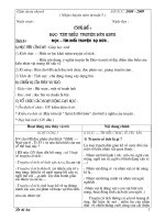
Figure 1 - Article 08-26-3
6.
Set up IDS to test FICM power by selecting:
• EOT
• B+
• FICM_LPWR
• FICM_MPWR
• FICM_VPWR
7.
After the glow plug wait to start light is off,
monitor EOT.
a. If EOT is less than 68 °F (20 °C) go to Step
8.
NOTE
RECORD FICM CALIBRATION NUMBER PRIOR
TO PERFORMING PROGRAM MODULE
INSTALLATION (PMI) AS IT WILL BE REQUIRED
LATER IN STEP 11.
4.
5.
b. If EOT is higher than specified use the
Instrumentation Gauge Tester 014-R1063 or
equivalent to simulate a cold engine by:
After checking the FICM calibration info,
perform a PMI on the FICM. This should be
done even if the FICM already had one of the
three (3) calibrations listed above.
(1)
Ignition off.
(2)
Disconnect EOT sensor Connector
C104.
Disconnect the glow plug control module
(GPCM) power wire C1249A, circuit 361 (RD)
from the passenger side battery. (Figure 1) This
also disconnects the alternator to minimize
power draw from the batteries and provide
more consistent FICM testing.
(3)
Connect the one lead of the instrument
gauge tester to the EOT sensor
connector C104-1, circuit 357 (GY/RD),
harness side and the other lead of the
instrument gauge tester to the EOT
sensor connector C104-2, harness side
circuit 354 (LG/RD).
(4)
Set the Gauge Tester to 80,000 ohms.
NOTE
THIS WILL SET GPCM CODES THAT NEED TO
BE CLEARED BEFORE RETURNING THE
VEHICLE TO THE CUSTOMER.
NOTE
IT IS EXTREMELY IMPORTANT TO CONFIRM
THE GAUGE TESTER SETTINGS WITH AN
OHMMETER TO ENSURE THAT THE GAUGE
TESTER IS IN THE CORRECT POSITION.
FAILURE TO FOLLOW THIS CHECK MAY
RESULT IN INACCURATE TEST RESULTS.
8.
PAGE 2
Turn key to run KOEO and check the B+ PID.
TSB 08-26-3 (Continued)
a. If B+ is not at least 11.5 V, then charge
batteries and return to Step 1.
b. If B+ is greater than 11.5 V, go to Step 9.
9.
Verify the following voltages and states. Use
the FICM ERROR STATE CHECKS chart
below.
Table for Step 9 - FICM ERROR STATE CHECK
FICM_
LPWR
FICM
_MPWR
DTC
11.5
MIN 45 V
None
0
MIN 45 V
P1378
0
Less than
45 V
P0611,
P1378
Check
FICM diagnostics - proceed to Step
11b
FICM LPWR fuse (15 amp) - proceed
to Step 10
FICM relay, 50 amp fuse - proceed to
Step 10
10. Disconnect the three (3) FICM connectors and
inspect condition of connector, pins, and wiring
at the connector, paying close attention for
wiring chafes. Repair any issues and reevaluate
vehicle, if the condition is corrected go to Step
11. If the condition is still present continue to
Step 10a.
NOTE
SOME COMMON CHAFING LOCATIONS ARE:
UPPER LEFT VALVE COVER, VALVE COVER
BOLT, AND INTAKE BOLTS, UNDER AND NEAR
THE FICM.
a. With a voltmeter check the following:
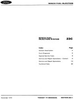
(1)
Check for B+ voltage at pin 27 of
connector 1388C and ground pins 1, 2,
3, 22 and 26, with the KOEO. (Figure
2 at end of article)
(a) If no, or low voltage is present,
repair as necessary.
(b) If B+ is present, proceed Step
10a(2).
(2)
Check for B+ voltage between pins 4,
7, 8, 23, 24, 25 and ground. (Figure 2
at end of article)
11. With IDS still connected, cycle key to off
position and then to on position within 2
seconds to start injector pre-cycle. While the
injectors are cycling (glow plug Wait to Start
Light is on), record the lowest observed
FICM_MPWR.
a. If FICM_MPWR drops below 45 V, replace
and reprogram the FICM (WSM 303-14B),
reconnect GPCM power, EOT connector if it
was removed to perform the test using the
Instrument Gauge Tester and return vehicle
to the customer.
b. If FICM_MPWR stays above 45 V or
greater, the DC-DC converter is good,
perform the following:
(1)
If the FICM did not have one of the
three calibrations listed in Step 3, then
it did not have the Inductive Heat
feature. Since the PMI performed in
Step 4 programmed this calibration into
the FICM, it will now address any
stiction concerns. If the vehicle
functions normally, reconnect GPCM
power and EOT connector if it was
removed to perform the test using the
Instrument Gauge Tester and return
vehicle to the customer.
(2)
If the FICM already had one of the
three calibrations listed in Step 3, then
injector stiction is not the concern,
proceed to Step 12.
12. Reconnect GPCM power and EOT connector if
it was removed to perform the test using the
Instrument Gauge Tester.
13. Perform KOEO injector electrical self test as
outlined in the Powertrain Controls/Emissions
Diagnosis (PC/ED) Section 2.
PART NUMBER
4C3Z-12B599-AARM
PART NAME
FICM Module
(a) If no or low voltage is found at any
pin, repair as necessary.
(b) If B+ is present at all pins, replace
the FICM, reference WSM
303-14B-1, reconnect the GPCM
power and EOT connector, clear
codes, and return vehicle to
customer.
PAGE 3
TSB 08-26-3 (Continued)
WARRANTY STATUS: Eligible Under Provisions Of
New Vehicle Limited
Warranty Coverage And
Emissions Warranty
Coverage
IMPORTANT: Warranty
coverage limits/policies are
not altered by a TSB.
Warranty coverage limits
are determined by the
identified causal part.
PAGE 4
OPERATION
MT082603
DESCRIPTION
TIME
Use SLTS Operations If
Actual
Available; Claim Additional
Time
Diagnosis Or Labor
Performed As Actual Time
DEALER CODING
CONDITION
BASIC PART NO.
CODE
12B599
42
Figure 2 - Article 08-26-3
PAGE 5