Subaru training technician reference manual 4EAT (automatic transmissions)
Bạn đang xem bản rút gọn của tài liệu. Xem và tải ngay bản đầy đủ của tài liệu tại đây (5.71 MB, 37 trang )
Technicians
Reference
Booklet
Automatic
Transmissions
(4EAT)
Module 302
© Copyright 2001
Subaru of America, Inc.
All rights reserved. This book may not be reproduced
in whole or in part without the express permission of
Subaru of America, Inc.
Subaru of America, Inc. reserves the right at any time
to make changes or modifications to systems,
procedures, descriptions, and illustrations contained
in this book without necessarily updating this
document. Information contained herein is considered
current as of February 2001.
© Subaru of America, Inc. 2001
4EAT Transmission
Table of Contents
Introduction ................................................................................................................................................................. 8
General Overview ........................................................................................................................................................ 8
Features ................................................................................................................................................................... 10
Major Components .................................................................................................................................................... 10
Lock-Up Torque Converter ........................................................................................................................................ 10
Lock Up Operating Modes ......................................................................................................................................... 11
Oil Pump Assembly .................................................................................................................................................. 12
Oil Pump Operation ................................................................................................................................................... 12
Transmission Gear Train ........................................................................................................................................... 13
Operating Principles: Rear Gear Set ......................................................................................................................... 13
High Clutch and Reverse Clutch ................................................................................................................................ 14
Operating Principles: Front Gear Set ......................................................................................................................... 14
Band Servo Operation ............................................................................................................................................... 14
Operating Principles: AWD ........................................................................................................................................ 15
Transfer Clutch Assembly (AWD) ............................................................................................................................. 15
AWD component details ............................................................................................................................................ 15
Final Drive ................................................................................................................................................................. 16
Oil Pump Housing Features ...................................................................................................................................... 16
Differential Carrier Features ....................................................................................................................................... 16
Hydraulic Control System ......................................................................................................................................... 16
Valve Body ............................................................................................................................................................... 17
Accumulators ............................................................................................................................................................ 17
Accumulator Operation .............................................................................................................................................. 17
Component Disassembly / Inspection ....................................................................................................................... 17
Drive Pinion .............................................................................................................................................................. 18
Reassembly .............................................................................................................................................................. 19
Clutch Reassembly Precautions ............................................................................................................................... 19
Differential Pinion Backlash ...................................................................................................................................... 19
Transfer Clutch Valve Assembly ............................................................................................................................... 19
Transmission Reassembly ........................................................................................................................................ 19
Torque Converter Case ............................................................................................................................................. 19
Final Drive Pre-load & Backlash ................................................................................................................................ 19
Forward Clutch Installation ........................................................................................................................................ 20
Reverse Clutch Drum End-Play ................................................................................................................................. 21
Total End-Play .......................................................................................................................................................... 21
Valve Body Precautions ............................................................................................................................................ 22
Extension Case ........................................................................................................................................................ 22
Transmission Reinstallation ...................................................................................................................................... 23
Electronic Control System ........................................................................................................................................ 23
Overview ................................................................................................................................................................... 23
Transmission Control Unit ......................................................................................................................................... 23
TCU Inputs ............................................................................................................................................................... 23
Legacy TCU Inputs ................................................................................................................................................... 25
Maintenance Precautions .......................................................................................................................................... 25
TCU Outputs ............................................................................................................................................................. 25
Shift Modes .............................................................................................................................................................. 26
Combination Meter Light Operation XT - 6 and L – Series ......................................................................................... 26
Late Model Combination Meter .................................................................................................................................. 27
Legacy, SVX, Impreza & Forester Lighting ............................................................................................................... 27
Fail Safe System ...................................................................................................................................................... 27
Fail Safe Components and Failure Results ................................................................................................................ 27
Self Diagnostic System ............................................................................................................................................ 28
XT and L-Series Diagnostics ..................................................................................................................................... 28
Contiuned on next page
February 2001
3
4EAT Transmission
1990 –1994 Legacy, 1992 – 1995 SVX, 1993 – 1995 Impreza Diagnostics ............................................................... 28
Select Monitor Analysis ............................................................................................................................................ 28
1995 – 1998 Legacy, 1996 – 1998 Impreza, 1996 – 1997 SVX, 1998 Forester, Diagnostics / OBD – II Vehicles ...... 29
Trouble Codes ........................................................................................................................................................... 29
OBD - II .................................................................................................................................................................... 29
OBD - II Operation Overview ..................................................................................................................................... 29
OBD - II purpose ....................................................................................................................................................... 29
Control Unit Networking ............................................................................................................................................. 30
Troubleshooting and Adjustments ............................................................................................................................. 31
Preliminary Inspection ............................................................................................................................................... 31
Gearshift Cable Adjustment ...................................................................................................................................... 31
Stall Test .................................................................................................................................................................. 31
Stall Test Results ..................................................................................................................................................... 31
Time Lag Test ........................................................................................................................................................... 31
Time Lag Results: ..................................................................................................................................................... 32
Pressure Test ........................................................................................................................................................... 32
On Car Service/Adjustments ..................................................................................................................................... 32
302 Module Lesson Plan Bulletins ............................................................................................................................ 34
302 Module Service Help-Line Updates ..................................................................................................................... 35
4EAT Valve Body Bolts ............................................................................................................................................ 36
February 2001
4
Slide Sequence
Slide No.
1
2
3
4
5
6
7
8
9
10
11
12
13
14
15
16
17
18
19
20
21
22
23
24
25
26
27
28
29
30
31
32
33
34
35
36
37
38
39
40
41
42
43
44
45
46
47
48
49
50
51
Description
Page No.
Title Slide (Four Speed Electronic Automatic Transmission) 4EAT
Created By
Teaching Aids
4EAT Assembly
XT Selector Lever
Legacy Selector Lever
Gear Ratios
Transaxle Control Unit
Transmission Features
Title Slide (Major Components)
Torque Convertors
Turbine Shafts
Torque Converter Components
Piston & Cover
Lock-up Clutch
Lock-up Operation (Artwork)
Duty Solenoid “B” (Artwork)
Lock-up Control Valve (Artwork)
Torque Converter (Artwork)
Oil Pump Assembly
Oil Pump Components
Oil Pump (Artwork)
Case Mating Surface Split Slide
Transaxle Gear Train
Rear Sun Gear
Rear Planetary Set
Overrunning Clutch Hub
Forward Clutch Drum (Artwork)
OWC 1-2
Low / Reverse Brake
O.R.C. Hub Installed
O.WC. 3 –4 Installed
Rear Internal Gear
Rev. & High Clutches
High Clutches
High Clutch Hub Bearings
Front Gear Set
Band & Servo
Servo Operation I (Artwork)
Servo Operation II (Artwork)
MPT Assembly
MPT Clutch Drum
Transfer Clutch & Drum
Title Slide (Final Drive)
Differential Housing
Oil Pump Housing
Oil Pump Cover Seals
Differential Carrier
MPT Power Flow
Title Slide (Lab Area)
Title Slide (Hydraulic Control System)
8
8
9
9
9
10
10
10
11
11
11
11
12
12
13
13
13
14
14
14
14
15
15
15
16
16
February 2001
5
Slide Sequence
Slide No.
52
53
54
55
56
57
58
59
60
61
62
63
64
65
66
67
68
69
70
71
72
73
74
75
76
77
78
79
80
81
82
83
84
85
86
87
88
89
90
91
92
93
94
95
96
97
98
99
100
101
102
Description
Page No.
Valve Body
Upper Valve Body
Lower Valve Body
Accumulators
Accumulator Operation
Title Slide (Lab Area)
Title Slide (Component Disassembly & Inspection)
Oil Pump Assembly
Measuring Rotor
Measuring Pump Housing
Checking Starting Torque
Drive Pinion Assembly
Measuring “A”
Torque pinion Bearing
Measuring “B”
Pinion Depth Formula
Mount Pinion to Housing
Title Slide (Reassembly)
Carrier Installed
Wrapping Stub Axles
Lip Seal Retainer
Zero State
Checking Backlash
Installing Retainer Assembly
Forward Clutch Drum Installation
Verifying Drum Installation
Measuring “M”
Measuring “m”
Measuring Total Clutch Pack Clearance
Selected Washers
Valve Body Precautions
Measuring “I” (MPT)
Measuring “L” (MPT)
Selecting Bearing
Lab Area (Reassembly)
Title Slide (Electronic control System)
Over view
TCU Locations
Throttle Sensor
Speed Sensor #1
Speed Sending Unit & Speedo Head
Combination Meter
Electric Speedometer System
Inhibitor Switch
Cruise Control
Temp. Sensor
Forced FWD Switch
Legacy TCU Inputs
Precautions
TCU Outputs
Shift Solenoids 1 & 2
16
17
17
18
18
18
18
19
20
20
20
21
21
22
22
22
22
23
24
24
25
25
February 2001
6
Slide Sequence
Slide No.
103
104
105
106
107
108
109
110
111
112
113
114
115
116
117
118
119
120
121
122
123
124
125
126
127
128
129
130
131
Description
Page No.
Component Application Chart
Shift Solenoid 3 & Duty solenoid “A”
Dropping Resistor
Duty Solenoid “B”
Duty solenoid “C”
Combination Meter XT-6
Late Mode Combination Meter
Title Slide (Fail Safe System)
Fail Safe System Components
Title Slide (Self Diagnostic Systems)
XT Combination Meter
XT Shift Quadrant
Code Interpretation
1990-1994 Legacy Diagnostics
Diagnostics OBD-II Vehicles
OBD-II Logic Tree
OBD-II DTC PO743
OBD-II DTC PO740
Control Unit Networking
Title Slide (Troubleshooting / Adjustments)
Preliminary Inspection
Cable Adjustment
Inhibitor Switch / Cable
Inhibitor Switch / Adjustment
Performance Tests
Pressure Test Gauge Set
Pump Outlet Pressure Test Port
ON car Service
Lab Area (Self Diagnosis / Fault Verification)
25
26
26
28
29
30
30
30
31
31
32
February 2001
7
4EAT Transmissions
Introduction
General Overview
This Technicians Reference Booklet introduces the first
generation of Subaru Four Speed Electronic Automatic
Transmissions. It covers the components and their
operation, its self-diagnostic system, troubleshooting,
transmission removal, inspection, reassembly, and
reinstallation procedures. The differences between the
front-wheel-drive (FWD) and the four-wheel-drive
(4WD) transmissions are also illustrated.
This booklet is designed to support the 4EAT
Transmission Core Course and in no way should it be
used to replace the service manual. The text and
illustrations are derived from classroom instruction and
lab participation.
4
The 4EAT Transmission, is a 4 speed, microprocessor
controlled transmission. It is not a 3 speed
Transmission with overdrive. It features a lock-up
torque converter, which locks up in all forward gears
except 1st. It is available in FWD or Full Time 4WD.
Ample room has been left throughout the booklet for
note taking. It is recommended that after completing
the course, this booklet should be filed in your personal
Technical Training Reference Booklets Binder
Binder,
which is sold through Subaru of America Parts
department (MSA5T0100B).
ALWAYS refer to the appropriate model year Subaru
Service Manual and applicable service bulletins for all
specifications and detailed service procedures. For
your convenience, a service bulletin and Service Help
Line Update index pages have been added to the back
of this booklet.
5
The shift quadrant has been designed in accordance
with the four forward speeds. In P, R, or N, there aren’t
any special features. With the selector in “D”, the
transmission shifts through all four gears. With the
selector in “3”, the transmission shifts 1, 2, 3. When
the selector is in the “2” position, the transmission shifts
through 1st and 2nd. If necessary, 3rd gear is computer
selected to prevent the engine from over-revving.
Manual 1st gear is only activated when the 1-HOLD
button is depressed and the shifter is in manually
selected “2”. This will provide engine braking. The
transmission will up-shift through 2nd and 3rd if
necessary, in order to prevent the engine from overrevving.
The 1-HOLD indicator is displayed on the combination
meter when the button is activated. When the computer
overrides the 1-HOLD gear selection the display will
change.
February 2001
8
4EAT Transmission
6
An enhanced version of the 4EAT was introduced with
the 1990 MY Legacy. Although similar in design to the
existing 4EAT, the shift quadrant is different. The
Legacy 4EAT has a seven-position quadrant: P-R-ND-3-2-1. The 1-HOLD button has been deleted and a
manual button has been added.
7
Refer to Service Manual for specific model
gear ratios.
When the selector is in 3rd range, manual switch “ON”,
the transmission will start in 2nd gear and shift to 3rd.
In 2nd range manual, the transmission starts and stays
in 2nd gear, but will up-shift to 3rd gear at 6500 RPM
to prevent damage to the engine. In 1st range manual
the transmission stays in 1st gear and also will upshift to second at 6,100 RPM to prevent damage to
the engine. Additionally, on 4WD vehicles, the TCU
applies a more aggressive 4WD map when the selector
is in the 1st position, manual switch “ON” or “OFF”.
These changes result in improved drive ability on low
friction road surfaces.
In 1995 the manual button was deleted. 3 select, shifts
1st, 2nd, and 3rd. 2 select, shifts 1st, 2nd. 1st select, stays
in 1st. 1995 through 1998 model year vehicles the TCU
controlled up-shift logic was replaced by a fuel cut logic.
8
The TCU monitors various engine and vehicle inputs,
i.e., throttle position and vehicle speed, etc. It also
controls the electronic shift solenoids in the
transmission. Refer to the appropriate MY service
manual, section 6-3 for the location of the TCU.
The 1993 Impreza was introduced with fuel cut logic,
never having an auto up shift logic.
1992 through 1997 SVX used the same shift logic as
the 1990 through 1994 Legacy. Retaining the Manual
button until production of the vehicle was discontinued
in 1997.
February 2001
9
4EAT Transmissions
Features
Major Components
11
9
The 4EAT features a double planetary gear set, a lockup torque converter, and variable displacement oil
pump. The 4WD system includes a Multi-Plate Transfer
Clutch (MPT).
The electronic control system is designed to reduce
shock during shifting, improve driving performance,
and improve fuel economy. A self-diagnostic system
is incorporated in order to improve serviceability and
reliability.
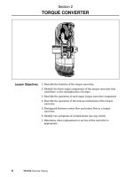
Lock-Up Torque Converter
The torque converter developed for the 4EAT is
designed to match a wide range of engines from large
to small displacement. It is also designed to improve
acceleration from a stop and reduce fuel consumption.
The electronically controlled Multi-Plate Transfer (MPT)
System provides for controlled transfer clutch torque.
It is designed to slip in order to eliminate torque bind
on cornering.
Shift control cable is a push pull type. Allowing for a
compact operating area and quiet operation.
12
1997 model year turbine shaft was redesigned as a
result of a torque converter change. The new shaft
has 23 splines’ verses 22 splines.
The torque converter has an electronically controlled,
hydraulic lock-up clutch system that prevents slip loss
during medium to high-speed operation. This system
replaces the previous centrifugal lock-up type clutch.
There is a friction surface on the back of the lock-up
clutch (piston) which locks against the back of the
impeller housing. Clutch engagement shock is
minimized in part, because of the torsional clutch
dampers and the wave spring/friction washer
combination.
February 2001
10
4EAT Transmission
16
The lock-up operation is controlled by the TCU which
then regulates Duty Solenoid “B” mounted on the lower
valve body. This solenoid provides control of the lockup valve located in the transmission upper valve body.
Finally, the lock-up valve activates the lock-up clutch
(piston) located in the torque converter.
Lock Up Operating Modes
18
In this condition, the control valve is pushed UPWARD
by the combined pilot pressure and spring force. This
allows regulated hydraulic pressure to enter the lockup release circuit.
In this condition, the control valve is pushed
DOWNWARD due to the reduced pilot pressure. As a
result, regulated hydraulic pressure is directed to the
lock-up apply circuit and the release circuit drains.
17
19
The TCU regulates the cycle of Duty Solenoid “B”.
When the duty solenoid operates at 5% duty, i.e.,
substantially more “OFF” than “ON”, pilot pressure is
directed to the lock-up control valve.
When Duty Solenoid “B” operates at 95% duty, i.e.,
substantially more “ON” than “OFF”, it reduces pilot
pressure to the control valve.
The release pressure then pushes the lock-up clutch
(piston) rearward and the lock-up clutch is released
from the impeller cover. On the other hand, oil drains
through the apply circuit to the oil cooler in the radiator.
The apply pressure then pushes the lock-up clutch
(piston) forward which engages the lock-up clutch with
the impeller cover. When engaged, the transmission
is coupled directly to the engine.
February 2001
11
4EAT Transmissions
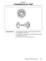
Oil Pump Assembly
A variable rate vane type pump is used for optimum
flow rate control with minimum energy loss. In addition
to pressurizing the oil, the pump provides lubrication
oil for the torque converter, the valves, the clutches,
low / reverse brake and the band.
22
21
The pump consists of the following components:
1.
2.
3.
4.
5.
6.
7.
8.
Rotor
Vanes
Control Piston
Vane Rings
Cam Ring
Return spring
Seal Ring
Oil Pump Cover
NOTE: THE ROTOR, V
ANES, CAM RING AND
VA
CONTROL PISTON ARE ALL SELECTIVE.
The pump rate is variable because of the cam ring
eccentricity. The eccentricity is adjusted automatically
corresponding to pressure from the regulating valve
acting upon the control piston.
Oil Pump Operation
During low speed operation, filtered ATF is drawn into
the pump suction port. The pump is driven directly at
engine speed and the ATF is then compressed by the
rotor vanes and discharged through the delivery port
in the oil pump cover. The pressurized ATF then flows
to the rest of the transmission case.
During high-speed operation, as the engine speed
increases, the delivery rate normally increases.
However, feedback pressure generated from the
regulator valve is applied to the control piston, which
pushes down the cam ring. This changes the
relationship between the cam ring and the rotor. In
this way, the pump delivery rate remains at a constant
value.
Cases were modified to prevent flexing of the line
pressure passage. This condition could cause a gasket
failure and reduced line pressure. As a result damage
to the high clutch and reverse clutch plates would
occur.
February 2001
12
4EAT Transmission
Transmission Gear Train
This compact unit features, a double planetary gear
set. It has a wide ratio between gears for improved
fuel efficiency as well as high performance.
Operating Principles: Rear Gear Set
The input shaft always powers the rear sun gear. The
rear planetary carrier (front internal gear) always
transmits power to the output shaft.
28
The forward clutch connects the rear internal gear to
the front planetary carrier (splined to the forward clutch
drum) through the O.W.C. 3-4. The overrunning clutch
is also used to connect the rear internal gear to the
forward clutch drum and the front planetary carrier.
26
The O.W.C. 1-2 (Sprague) prevents the forward clutch
drum from rotating counterclockwise. The sprague is
applied when the transmission is operating in D-1 or
3-1.
The Low/Reverse brake is splined to the case. It holds
the forward clutch drum in order to prevent it from
turning when the transmission is in Reverse, 2-1, and
1-HOLD.
The overrunning clutch provides engine braking during
deceleration except in D-1 and 3-1.
27
The one way clutch (O.W.C.) 3-4 prevents the rear
internal gear from turning counterclockwise. Its inner
race is the rear internal gear and its outer race is the
forward clutch hub. The overrunning clutch hub is also
connected to the rear internal gear by dogs.
The O.W.C. 3-4 is used in 1st, 2nd, and 3rd gears.
The forward clutch is used in all forward gears.
The rear internal gear is controlled by the forward
clutch through the O.W.C. 3-4. Additionally, the rear
internal gear is controlled by the overrunning clutch.
Functioning as an input member in 3rd. Fixed member
in 1st and free member in reverse.
February 2001
13
4EAT Transmissions
High Clutch and Reverse Clutch
Operating Principles: Front Gear Set
The high clutch drum (reverse clutch hub) is splined
to the input shaft. It supplies power to the reverse
clutch and the high clutch. The high clutch hub is
splined to the front planetary carrier. When the reverse
clutch is applied for Reverse gear it powers the front
sun gear. When the high clutch is applied in 3rd and
4th gear it powers the front planetary carrier via the
high clutch hub.
37
The front sun gear is dogged to the reverse clutch
drum. It functions to be the main input member in
reverse, never used as an output member. It serves
as a fixed member in 2nd & 4th gear. Is a free rotating
member in 1st & 3rd gear.
34
Lubrication holes for the high clutch bearing were
changed from the original, with 3 – 1mm holes. The
second version had 3 – 1.5mm holes. The third and
final version has 6 – 2mm holes.
The front planetary carrier is splined externally to the
high clutch drum. It functions, as an input member in
3rd & 4th, never used as an output member. It serves
as a fixed member in 1st & reverse. And a free rotating
member in 2nd.
Band Servo Operation
38
36
The high clutch bearing race was modified to improve
lubrication. Race width was reduced to work better
with the enlarged lubrication holes (the bearing on the
left pictured above has the modified race) of the high
clutch. Bearing position is critical when installed.
The band is applied in 2nd and 4th gears by a twostage servo, which is controlled by accumulators.
February 2001
14
4EAT Transmission
Operating Principles: AWD
Transfer Clutch Assembly (AWD)
The transfer unit consists of a hydraulic multi-plate
clutch and a hydraulic control system incorporating a
duty solenoid. It is housed in the extension case at the
rear of the transmission. A caged needle bearing
supports the clutch on the reduction drive shaft and a
ball bearing supports the clutch in the case.
39
In order to obtain second gear the servo is in the 2Apply mode. Hydraulic pressure from the 2A
accumulator pushes the 1-2 piston UPWARD, which
tightens the band.
Duty solenoid “C” regulates the MPT clutch. It is
controlled by the TCU, which determines the degree
of AWD by altering the duty ratio. As the duty ration
increases the amount of AWD decreases.
The clutch itself features friction discs that are designed
to slip. This eliminates torque binding during tight
cornering. In order to get power to the front wheels;
the reduction gear powers the reduction driven gear,
which is attached to the drive pinion shaft.
AWD component details
For the rear wheels, power goes from the reduction
drive shaft to the MPT clutch hub, which is welded to
the drive gear. The power is transferred through the
MPT clutch where it outputs to the rear drive shaft.
Reduction shaft seal rings direct fluid from the hollow
shaft to the lubrication circuits inside the transmission.
Beginning in the 1990 model year a new transfer piston
was added. This improved torque split control,
preventing the MPT clutch from further applying during
high speed driving. Cancels centrifugal pressure
buildup affect, behind the clutch apply piston.
40
For third gear, the servo is in the 3-Release mode. In
this case, hydraulic pressure from the 3R accumulator
aided by the return spring pushes the 1-2 piston
DOWNWARD in order to release the band.
For fourth gear 4-Apply mode, hydraulic pressure from
the 4A accumulator pushes the 3-4 piston UPWARD
in order to apply the band.
43
Transfer clutch hub is welded to the reduction drive
gear. Bringing power into the MPT clutch assembly.
The reduction shaft seal rings direct fluid from the
hollow shaft to the lubrication circuits inside the
transaxle.
February 2001
15
4EAT Transmissions
The plug on the end of the shaft has a small hole for
maintaining lubrication pressure and directing
lubrication oil to the clutch drum caged needle bearing.
The transfer clutch drive and driven plates are sold as
a set. The plates are “broken in” as part of the
manufacturing process. It is necessary to keep in
specific order they are packed when installing them
into the old drum. Also to order the correct set you
must measure the existing clutch pack clearance
selective plate.
Differential Carrier Features
The ring gear is mounted on the right side of the carrier.
This design adds to its compactness and makes it
easier to service. The backlash is easily adjustable
through the carrier bearing retainers.
Final Drive
The hypoid gear set is mounted in the aluminum torque
converter case. Supported by tapered roller bearings.
Differential carrier housing has removable stub axle
shafts. The pinion is mounted through the oil pump
housing.
Oil Pump Housing Features
48
The housing is made of cast iron for greater rigidity.
Double taper roller bearings are used to support the
pinion. This allows for the thermal expansion of two
dissimilar metals: aluminum and cast iron. These
bearings also improve the durability and reliability of
the unit. The bearings are preloaded by a locknut,
which allows for easy serviceability.
Hydraulic Control System
52
46
Pinion depth is set by shims, which are located
between the bearing flange and the oil pump housing.
A double-lip oil seal separates transmission fluid from
the hypoid gear oil. This greatly improves the fluid
system reliability.
February 2001
16
4EAT Transmission
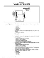
Valve Body
The valves and solenoids control the lubrication circuits,
the lock-up torque converter, shifting, etc.
Component Disassembly /
Inspection
The valve body is divided into two major sections: upper
and lower.
The valve body works in conjunction with the TCU. It
is designed to provide smooth shift control and
component longevity. It also reduces unnecessary high
pressure in certain instances. As an example, line
pressure is lowered between shifts.
The valve body features shift step control. This means
that gear members are momentarily applied between
shifts it allows them to be brought up to speed, which
reduces shock.
59
Accumulators
There are four accumulators mounted in the
transmission case:
•
•
•
•
4-Apply (4A)
2-Apply (2A)
3-Release (3R)
Neutral/Drive (ND)
In order to inspect the oil pump assembly, remove the
pump cover and then lift out the pump components.
Examine the piston and cam ring seal. Check the rotor,
piston, vanes, and cam ring for cuts, gouges, etc.
Replace any components that show evidence of
excessive wear or damage.
They are designed to lessen shift shock by absorbing
the sudden pressure change generated when a circuit
is activated. This ensures smooth component
application. The accumulator resistance will vary in
direct proportion to the line pressure.
Accumulator Operation
Accumulators normally operate at a fixed rate in other
automatic transmissions. Therefore, as the
transmission pressure rise, the accumulator cannot
further compensate due to the constant value of the
spring. Pressure shocks are thus transferred to the
components.
In the 4EAT Accumulators, however, the line pressure
is applied to the back of the accumulator piston.
Therefore, the resistance to pressure is proportionally
increased hydraulically. This keeps the pressure shock
under control, allowing smoother component
application.
60
Measure the pump components in at least four
positions in order to maintain correct component to
housing clearance.
An additional accumulator is located in the lower section
of the valve body, next to the manual valve. It absorbs
line pressure pulses created by the sudden changes
in the pressure.
February 2001
17
4EAT Transmissions
63
61
Disassemble the drive pinion shaft and examine the
components for gouges, cuts, damage, etc.
Measure the oil pump housing depth in several places.
Then subtract the readings from the previous
measurements. Finally, check the wear limits in order
to determine the proper clearance when installing new
components. Select vanes, which are the same height
as the rotor.
NOTE: SHOULD THE ROTOR OR V
VANES
ANES REQUIRE
REPLA
CEMENT
REPLACEMENT
CEMENT,, BE SURE THEY ARE BOTH THE SAME
HEIGHT
HEIGHT..
NOTE: REINST
ALL LIBER
Y LUBRICA
TA
RA
AT
A L LLY
TED
COMPONENTS. THE DOUBLE LIP SEAL AND
ALLED LA
RET
AINER WILL BE INST
RETAINER
INSTALLED
LATER.
TER.
64
Drive Pinion
Next, determine the pinion depth. A two step process
is used to determine the number of shims and the
thickness of the shims.
First, measure the thickness of the pinion gear and
record this as measurement “A”.
NOTE: DIMENSION ““A
A” INCL
UDES THE THICKNESS
INCLUDES
OF THE TOOL.
62
Then install the flange assembly with bearings using
a new O-ring and carefully install the collar and washer
with a new nut. Make sure the bearings are lubricated
and then torque the nut to specifications. Use special
tools #499787100 Wrench and #498937100 Holder.
Be sure to stake the new lock nut in place.
Prior to disassembling the pinion shaft, verify proper
starting torque of the bearings.
IF THE REP
AIR IS FOR OTHER THAN A RING AND
REPAIR
PINION LLUBRICA
UBRICA
URE THIS SHOULD BE
UBRICATION
FAIL
AILURE
TION F
AIL
DONE FIRST
FIRST.. SO A NEW BEARING CAN BE ORDERED
PRIOR TO REASSEMBL
Y IF OUT OF SPECIFICA
TIONS.
REASSEMBLY
SPECIFICATIONS.
IF THERE IS A RING AND PINION LLUBRICA
UBRICA
TION
UBRICAT
FAIL
URE, Y
OU WILL MORE THAN LIKEL
Y NEED A NEW
AILURE,
YOU
LIKELY
BEARING.
IF THE BEARING IS OUT OF SPECIFICA
TIONS, NEW
SPECIFICATIONS,
ROLLER BEARINGS ARE REQUIRED. DO NOT
O VER
TIGHTEN THE LLOCK
OCK NOT TO COMPENSA
TE.
VERTIGHTEN
COMPENSATE.
February 2001
18
4EAT Transmission
Examine the band friction surface for wear or damage
and carefully check the servo and accumulator sealing
rings. Note that many different sizes are used. Do not
confuse the locations of the components or seals. Also
check the bores for scoring damage. Lubricate the
components liberally with ATF during reassembly.
Inspect the differential carrier components for wear,
cuts or damage. Then reassemble the ring gear to
the carrier.
Differential Pinion Backlash
Perform the following calculation in order to determine
the shim thickness (t) in millimeters.
In order to verify the carrier backlash, temporarily,
install the stub axle backwards and set up a dial
indicator against the side gear. Then lock the pinions
with a screwdriver and rotate the axle shaft. Verify the
backlash reading. Correct the backlash if it is not within
specifications. To change the backlash, disassemble
the carrier and change the selective thrust washer(s)
located behind each side gear.
FORMULA: t = 6.50 ± 0.0125 - (B - A)
Transfer Clutch Valve Assembly
66
For the second step of the pinion depth measurement,
the combined thickness of the flange and pinion must
be determined. Record this as measurement “B”.
•
t = Thickness of drive pinion shim(s)
•
6.50 ± 0.0125 = Ideal distance of pinion
protrusion from oil pump housing
•
B = Thickness of pinion and flange
•
A = Thickness of pinion
In the transfer case, inspect and clean the valve body
assembly. This includes the transfer clutch valve and
the pilot valve. Also examine the strainer located in
the case. Clean as necessary.
Transmission Reassembly
Finally, mount the pinion to the housing using the
selected shim(s).
NOTE: NO MORE THAN 3 SHIMS MA
Y BE USED. REFER
MAY
TO SECTION 3-2, [W8C8], SUBARU SERVICE MANUAL
TO DETERMINE THE PROPER SHIM SELECTION.
NOTE: EA
CH AND EVER
Y REASSEMBL
Y STEP IS NOT
EACH
EVERY
REASSEMBLY
BEING COVERED IN THIS BOOKLET
T.. T H E Y A R E
CO
VERED IN THE SER
VICE MANU
AL. ONL
Y THE KEY
COVERED
SERVICE
MANUAL.
ONLY
R E A S S E M B LLY
Y STEPS/MEASUREMENTS WILL BE
CO
VERED IN THIS POR
TION OF THE BOOKLET
PORTION
BOOKLET..
COVERED
Torque Converter Case
Reassembly
Inspect the clutches for damage caused by normal
wear, heat, contamination, or component failure.
Also examine the sealing ring and the lip seals for
damage, and see that the check balls aren’t sticking.
Clutch Reassembly Precautions
Install the differential carrier into the case being careful
of the nylon speedo gears. Then insert the stub axle
shafts using new snap rings and check the axle shaft
thrust play.
Next, wrap the stub axles with vinyl tape and install
the carrier bearing retainers. Screw in the right retainer
further than the left retainer. This prevents potential
damage to the ring and pinion.
•
Orient the dish plates correctly.
•
Lubricate the components liberally with ATF
and allow time to soak.
Final Drive Pre-load & Backlash
•
Measure the clutch pack clearance between
the retaining plate and the snap ring.
•
All retaining plates are selective. See the service
manual sec. 3-2, pg. 83.
Install the oil pump housing using four bolts. Take extra
precaution to protect the sealing surface from bolt
damage by temporarily installing gasket material under
the bolt heads.
•
Verify their operation with air pressure.
February 2001
19
4EAT Transmissions
NOTE: THE LIP SEAL RET
AINER CAN BE INST
RETAINER
INSTALLED
ALLED
BEFORE OR AFTER PREFORMING THE BACKLASH
ADJUSTMENT
ATION OF THE LIP
ADJUSTMENT.. CHECK THE ORIENT
ORIENTA
SEALS AND USE THE SPECIAL TOOL #4992457300
ALL IT A
T THE CORRECT DEPTH.
INSTALL
AT
TO INST
In order to check the backlash; mount a dial indicator
securely so that it extends through the drain hole. Then
lock the pinion shaft using the special tool #499787100
(Wrench), and check the backlash.
In order to change the backlash; rotate the retainers
an equal amount in opposite directions. This maintains
the proper pre-load. In order to increase backlash,
loosen the LH retainer and tighten the RH retainer. In
order to decrease backlash, tighten the LH retainer
and loosen the RH retainer. One notch of the retainer
equals 0.002 in. or (0.05mm).
Finally, mark the position of the retainers, and remove
them so they can be reinstalled with their O-rings. Also
reinstall and secure the lock-plates.
Forward Clutch Installation
73
NOTE: THE LLOW/REV
OW/REV BR
AKE HAS ALREAD
Y BEEN
BRAKE
ALREADY
INST
ALLED.
INSTALLED.
Next, rotate the pinion several times using the following
special tools:
•
#499787100 Wrench
•
#498937100 Holder
In order to set the pre-load, the “zero” state must be
established first. Tighten the LH retainer and loosen
the RH retainer until contact is felt while rotating the
shaft. Repeat this process several times to confirm
the point at which the contact is felt. This is the “zero”
state.
After the “zero” state is established, back off the LH
retainer 3 notches and secure it with the locking tab.
Then back off the RH retainer and retighten until it
stops. Repeat this procedure several times. Tighten
the RH retainer 1 3/4 notches further. This sets the
pre-load. Finally, secure the retainer with its locking
tab.
77
Install the forward clutch drum into the low/rev brake.
Rotate the drum carefully during installation. It can only
rotate clockwise due to the O.W.C. 1-2.
In order to verify a proper installation; check the
relationship between the drum and the O.W.C. 1-2
inner race. The race should protrude slightly.
74
February 2001
20
4EAT Transmission
Reverse Clutch Drum End-Play
NOTE: THE BALANCE OF THE GEAR TR
AIN
RA
COMPONENTS HAS ALREAD
Y BEEN INST
ALLED.
ALREADY
INSTALLED.
Select a washer for proper end-play adjustment using
the following formula.
FORMULA (mm):
•
t = (M + 0.40) - m - (0.55 to 0.90)
•
t = thickness of thrust washer (to be
determined)
•
M = Distance from top of case to reverse
clutch drum
•
0.40 = Thickness of gasket
•
m = Distance from reverse clutch thrust
surface (on oil pump cover) to oil pump
housing
•
0.55 to 0.90 = Ideal reverse clutch endplay
79
Then measure “m” using the same measuring block
and depth gauge. Finally, perform the calculations to
determine “t” (large washer). Choose the proper thrust
washer as listed in the service manual, sec. 3-2,
[W4B2]. Subaru Service Manual to determine the
correct thrust washer.
Total End-Play
Select a washer for total endplay using the following
formula:
FORMULA (mm):
78
First measure “M” using a depth gauge noting that no
gasket is used. Measure where the thrust washer
contacts the drum and record the reading.
•
T = (L + 0.40) - l - (0.25 to 0.55)
•
T = Thickness of race
•
L = Distance from case to reverse clutch
drum race surface
•
0.40 = Thickness of gasket
•
l = Distance from top of oil pump cover
needle bearing to oil pump housing
•
0.25 to 0.55 = Ideal total end-play
First measure “L” using a depth gauge. Again, note
that there is no gasket. Measure to the race surface
and record the reading.
February 2001
21
4EAT Transmissions
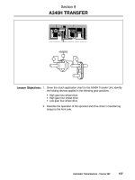
Extension Case
In order to determine the endplay measurement
(4WD), measure the distance from the extension case
gasket surface to the transfer clutch thrust surface
(4WD) using the formula below.
80
Next, measure “l” using the same measuring block.
With the bearing in place, record the reading. Perform
the calculations to select “T” (small 3 tanged washer).
Refer to sec. 3-2, [W4B2] Subaru Service Manual to
determine the correct thrust washer.
83
Valve Body Precautions
82
•
Route the harness correctly.
•
Torque the mounting bolts evenly.
•
Use a new O-ring on the strainer.
•
Install the oil cooler pipe.
•
Make sure the magnet is properly
positioned on the pan.
•
Torque the pan bolts evenly.
84
NOTE: HEIGHT OF GA
UGE TOOL #499577000 MUST
GAUGE
BE SUBTRACTED FROM L.
February 2001
22
4EAT Transmission
FORMULA (mm):
• T = (L + 0.40) - l - (0.05 to 0.25)
•
T = Thickness of thrust bearing
•
L = Distance from extension case gasket
surface to transfer clutch thrust surface
•
0.40 = Gasket thickness
•
l = Distance from transmission case gasket
surface to reduction drive gear thrust
surface
•
0.05 to 0.25 = Ideal end-play
Select the proper bearing/washer from the chart in
sec. 3-2, [W4B6] pg. 78 Vol. 2 of the 1995 service
manual.
In order to determine the endplay measurement for
FWD vehicles, use the same procedure as 4WD
except:
•
T = Thickness of thrust washer
•
L = Distance from rear cover to reduction
drive shaft bearing mounting surface
•
l = Distance from transmission case to
bearing surface
Transmission Reinstallation
Reverse the order of removal except for the following
procedures:
Electronic Control System
Overview
The electronic control system consists of various inputs
(sensors) and outputs (lights and solenoids) in addition
to the Transmission Control Unit (TCU).
This is the second generation of Subaru automatic
transmission. In addition to being smoother and
quieter, it is designed to help maximize fuel economy
while providing performance.
It monitors the engine and transmission performance
conditions, the driver’s demands and the vehicle
speed.
Transmission Control Unit
The TCU is a highly sophisticated microprocessor with
a self-diagnostic long-term memory. It also has a failsafe function, which maintains driveability in case of a
major electrical component failure.
In a transmission equipped for 4WD the TCU utilizes
a program which continually changes the degree of
4WD based upon vehicle operating condition(s).
The TCU controls shifting and line pressure in addition
to the lock-up torque converter and the MPT clutch.
TCU Inputs
•
•
•
•
•
•
•
•
•
•
1. Torque the rear cross member bolts to
specification.
2. Use new axle spring pins, making sure the
chamfered DOJ and stub axle holes align.
3. Torque the transverse link bolts noting that the
vehicle must be on the ground.
4. Install the gearshift cable and verify proper
gearshift operation.
5. Install the pitching stopper by tightening the
body side bolt first.
6. Add differential fluid and ATF.
7. Road test the vehicle.
8. Re-check the fluids for the proper level or leaks.
Whenever performing any service work on the 4EAT
Transmission ALWAYS use the appropriate Subaru
Service Manual.
Throttle sensor/idle switch
Vehicle speed sensor #1
Vehicle speed sensor #2
Tachometer signal
Inhibitor switch
Cruise control signal
ATF temperature sensor
Ignition/battery voltage
1-HOLD switch
Forced FWD
90
February 2001
23
4EAT Transmissions
The throttle sensor/idle switch is basically electrical
throttle pressure. The load signal effects: shifting, line
pressure and lock-up. The closed throttle input effects
the lock-up release mode as well as smooth
downshifting into 2nd gear. It also causes a reduction
in the pressure.
The Speedometer Driving Unit (SDU) receiving pulses
from the MRE sensor processes the signal sending
the information to the transmission control unit.
The TCU compares the speed signal from the front
output shaft with the signal from the rear output shaft
(sensor #1). The speed differential helps the TCU
determine the degree of 4WD (along with other inputs).
The tachometer signal effects the shift points at kickdown. The TCU uses the signal to prevent the engine
from over-revving.
NOTE: THE T
TCU
OVERRIDE
CU WILL O
VERRIDE THE INHIBITOR
CH, IF NECESSAR
Y, IN ORDER TO PREVENT THE
SWITCH,
NECESSARY
SWIT
ENGINE FROM O
VER-REVVING.
OVER-REVVING.
91
Vehicle speed sensor #1 is mounted to the
transmission and is basically electrical governor
pressure. It is used to detect vehicle speed and it effects
shift points, lock-up, and line pressure.
The cruise control signal tells the TCU of cruise control
activation. This allows for a wider operating range in
4th gear unless a large speed differential exists from
the set speed in which case the transmission may
downshift. This improves fuel economy.
In FWD transmissions, the speed sensor reads parking
gear rotation at the front output shaft. In 4WD
transmissions, it senses the transfer clutch drum
rotation at the rear output shaft.
Vehicle speed sensor #2 is built into the combination
meter. In FWD units, it is used as a back up for speed
sensor #1. In 4WD units, it is used as the front output
shaft speed sensor.
97
The ATF temperature sensor is located on the lower
valve body next to duty solenoid “B”. When the ATF is
cold, the TCU won’t allow an up-shift into 4th gear.
The object is to warm the engine quickly for lower
emissions. It is more sophisticated than the KDLH
system and less objectionable for the consumer.
92
Starting with SVX introduction in 1992, then added to
1995 Legacy, 1996 Impreza, 1998 Forester an electric
speedometer system was introduced. The system uses
a Magnetic Resistance Effect (MRE) type speed sensor
driven by a conventional speedometer drive gear
system. The speed sensor, which generates four
pulses per revolution, is located on the front differential
housing.
When the ATF is hot (4WD only), the TCU shifts the
transmission as if in the POWER mode. This pushes
the shift points higher which allows the engine to run
faster. The oil pump then circulates ATF through the
oil cooler more quickly so as not to overheat the engine
coolant.
The TCU also monitors system voltage in order to
correctly interpret the inputs and alter the control of
the outputs. For example, the system is designed for
12-volt operation. When running, however, most
vehicles have other than 12 volts available.
February 2001
24
4EAT Transmission
The 1-HOLD switch is located aft of the shift quadrant.
When activated, it creates a forced 1st gear.
NOTE: THE T
CU WILL SHIF
T 2ND TO 3RD IF
TC
FT
NECESSAR
Y, IN ORDER TO PREVENT THE ENGINE
NECESSARY
FROM O
VER-REVVING.
OVER-REVVING.
TCU Outputs
There are two types of outputs, solenoid controls and
light controls. The solenoids control shifting, line
pressure, lock-up and 4WD.
The light controls indicate operating conditions to the
driver. They indicate the POWER mode, manually
selected 1st or 2nd gear, or hot ATF (4WD only).
On the 1990 M.Y. and later Legacy the light controls
indicate hot ATF (FWD and 4WD), gears 3 - 2 - 1,
MANUAL mode, and POWER mode.
98
The FWD switch changes the driving mode from 4WD
to FWD. The FWD switch is located on the left front
shock tower. It is activated by inserting the spare fuse
into the under hood connector. The FWD light on the
combination meter verifies that the vehicle is in FWD.
Legacy FWD switch is located on the right strut tower.
SVX and Forester switch is located in the main fuse
box.
Legacy TCU Inputs
The Legacy fuel system ECM, beginning with MY
1990, sends new inputs to the TCU for line pressure
control.
It networks the MPFI ECU RPM signal and altitude
compensation inputs. This provides additional line
pressure control for high altitude compensation to
reduce shift shock. ABS system inputs turn “OFF” the
over-running clutch when ABS is active and fixes the
duty ratio of the MPT to mostly FWD.
102
Shift solenoids #1 and #2 are located on the upper
valve body. The TCU induces “ON/OFF” conditions,
which regulate the shifting of the forward gears.
When a shift solenoid is “ON”, it passes pilot pressure
to shift valve “A” and/or shift valve “B”. The valve(s)
will then shift, feeding the appropriate controlling
member circuits (high clutch, band, etc.).
NOTE: PILOT PRESSURE IS NOTHING MORE THAN
A PRESSURE HELD AT A CONSTANT VALUE.
When a shift solenoid is “OFF”, the affected shift valve
will move to its static position due to spring pressure.
The appropriate controlling member circuit will than
be fed (high clutch, band, etc.).
Maintenance Precautions
Before jacking up one or two wheels for
maintenance with the engine running or before
running the vehicle on a chassis dynamometer,
the electronic 4WD engagement system MUST be
disengaged by installing the spare fuse (15A) of
the fuse box into the FWD connector located
under the hood. Failure to do so could result in
movement of vehicle. (Refer to owner’s manual)
103
February 2001
25