Tài liệu Automatic Transmissions P2 doc
Bạn đang xem bản rút gọn của tài liệu. Xem và tải ngay bản đầy đủ của tài liệu tại đây (477.22 KB, 15 trang )
6 TOYOTA Technical Training
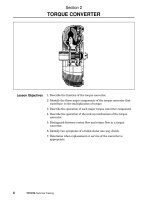
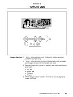
1. Describe the function of the torque converter.
2. Identify the three major components of the torque converter that
contribute to the multiplication of torque.
3 Describe the operation of each major torque converter component.
4. Describe the operation of the lock−up mechanism of the torque
converter.
5. Distinguish between vortex flow and rotary flow in a torque
converter.
6. Identify two symptoms of a failed stator one−way clutch.
7. Determine when replacement or service of the converter is
appropriate.
Section 2
TORQUE CONVERTER
Lesson Objectives
TORQUE CONVERTER
Automatic Transmissions - Course 262 7
The torque converter is mounted on the input side of the transmission
gear train and connected to a drive plate. The drive plate, or flex plate
as it is sometimes referred to, is used to connect the converter to the
crankshaft flywheel flange of the engine. The ring gear, which the
starter motor engages to turn the engine, is attached to the drive plate.
Torque Converter
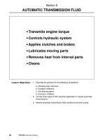
Transmits engine torqueto
the transmissioninput shaft.
Role of the torque converter:
• Multiplies torque generated by the engine.
• Serves as an automatic clutch which transmits engine torque to the
transmission.
• Absorbs torsional vibration of the engine and drivetrain.
• Smoothes out engine rotation.
• Drives the oil pump of the hydraulic control system.
The torque converter is filled with automatic transmission fluid, and
transmits the engine torque to the transmission. The torque converter
can either multiply the torque generated by the engine or function as a
fluid coupling.
The torque converter also serves as the engine flywheel to smooth out
engine rotation as its inertia helps to maintain crankshaft rotation
between piston power pulses. It tends to absorb torsion vibration from
the engine and drivetrain through the fluid medium since there is no
direct mechanical connection through the converter.
In addition, the rear hub of the torque converter body drives the
transmission oil pump, providing a volume of fluid to the hydraulic
system. The pump turns any time the engine rotates, which is an
SECTION 2
8 TOYOTA Technical Training
important consideration when a vehicle is towed. If the vehicle is towed
with the drive wheels on the ground and the engine is not running, the
axles drive the transmission output shaft and intermediate shaft on
bearings that receive no lubrication. There is a great potential for
damage if the vehicle is towed for a long distance or at greater than low
speeds.
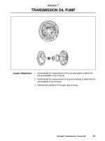
The torque converter’s three major components are; the pump impeller,
turbine runner and the stator. The pump impeller is frequently
referred to as simply the impeller and the turbine runner is referred to
as the turbine.
The impeller is integrated with the torque converter case, and many
curved vanes that are radially mounted inside. A guide ring is installed
on the inner edges of the vanes to provide a path for smooth fluid flow.
Torque Converter
- Impeller
The vanes of the stator
catch the fluid as it leaves
the turbine and redirects it
back to the impeller.
When the impeller is driven by the engine crankshaft, the fluid in the
impeller rotates with it. When the impeller speed increases, centrifugal
force causes the fluid to flow outward toward the turbine.
Torque Converter
Components
Pump Impeller
TORQUE CONVERTER
Automatic Transmissions - Course 262 9
The turbine is located inside the converter case but is not connected to
it. The input shaft of the transmission is attached by splines to the
turbine hub when the converter is mounted to the transmission. Many
cupped vanes are attached to the turbine. The curvature of the vanes is
opposite from that of the impeller vanes. Therefore when the fluid is
thrust from the impeller, it is caught in the cupped vanes of the turbine
and torque is transferred to the transmission input shaft, turning it in
the same direction as the engine crankshaft.
Torque Converter
- Turbine
Fluid is caught in
the cupped vanes
of the turbine and
torque is transferred
to the input shaft.
Before moving on to the next component of the torque converter we
need to examine the fluid coupling whose components we have just
described. When automatic transmissions first came on the scene in
the late 1930s, the only components were the impeller and the turbine.
This provided a means of transferring torque from the engine to the
transmission and also allowed the vehicle to be stopped in gear while
the engine runs at idle. However, those early fluid couplings had one
thing in common; acceleration was poor. The engine would labor until
the vehicle picked up speed. The problem occurred because the vanes
on the impeller and turbine are curved in the opposite direction to one
another. Fluid coming off of the turbine is thrust against the impeller
in a direction opposite to engine rotation.
Notice the illustration of the torque converter stator on the following
page; the arrow drawn with the dashed lines represents the path of
fluid if the stator were not there, such as in a fluid coupling. Not only is
engine horsepower consumed to pump the fluid initially, but now it also
has to overcome the force of the fluid coming from the turbine. The
stator was introduced to the design to overcome the counterproductive
force of fluid coming from the turbine opposing engine rotation. It not
only overcomes the problem but also has the added benefit of
increasing torque to the impeller.
Turbine Runner
Fluid Coupling
SECTION 2
10 TOYOTA Technical Training
The stator is located between the impeller and the turbine. It is
mounted on the stator reaction shaft which is fixed to the transmission
case. The vanes of the stator catch the fluid as it leaves the turbine
runner and redirects it so that it strikes the back of the vanes of the
impeller, giving the impeller an added boost or torque. The benefit of
this added torque can be as great as 30% to 50%.
Torque Converter
- Stator
The vanes of the stator
catch the fluid as it leaves
the turbine and redirects it
back to the impeller
The one−way clutch allows the stator to rotate in the same direction as
the engine crankshaft. However, if the stator attempts to rotate in the
opposite direction, the one−way clutch locks the stator to prevent it
from rotating. Therefore the stator is rotated or locked depending on
the direction from which the fluid strikes against the vanes.
Stator
TORQUE CONVERTER
Automatic Transmissions - Course 262 11
Now that we’ve looked at the parts which make up the torque
converter, let’s look at the phenomenon of fluid flow within the torque
converter. When the impeller is driven by the engine crankshaft, the
fluid in the impeller rotates in the same direction. When the impeller
speed increases, centrifugal force causes the fluid to flow outward from
the center of the impeller and flows along the vane surfaces of the
impeller. As the impeller speed rises further, the fluid is forced out
away from the impeller toward the turbine. The fluid strikes the vanes
of the turbine causing the turbine to begin rotating in the same
direction as the impeller.
After the fluid dissipates its energy against the vanes of the turbine, it
flows inward along the vanes of the turbine. When it reaches the
interior of the turbine, the turbine’s curved inner surface directs the
fluid at the vanes of the stator, and the cycle begins again.
Stator Operation
The stator one-way clutch
locks the stator
counterclockwise and
freewheels clockwise.
Converter
Operation