Bảng tính cầu Cổ Cò (Co co calculation)
Bạn đang xem bản rút gọn của tài liệu. Xem và tải ngay bản đầy đủ của tài liệu tại đây (11.03 MB, 260 trang )
CDM Project Office for Danang City PIIP
8th Floor of CIENCO 5 Tower
77 Nguyen Du Street, Hai Chau District, Danang City, Vietnam
Tel. 05 11 388 6778 |
Fax. 05 11 388 6998
eMail:
DANANG PRIORITY INFRASTRUCTURE INVESTMENT PROJECT- DANANG PIIP
PACKAGE: A23+ A24+ B27
-----------------Phase 2- Detailed Design
SUBCOMPONENT C57 : CO CO BRIDGE
CALCULATION
Danang, 29 December 2011
Contents
1. Structural Design Criteria
1.1
1.2
1.3
1.4
1.5
1.6
1.7
General
Design Standards and Codes of Practice
Horizontal and Vertical Clearance
Materials
Loads
Load Factors and Combinations
Design Considerations / Limit States
1
5
6
7
10
32
36
2. Structural Model
47
3. Seismic Load on Bridge
62
4. Foundation and Pile Design
70
5. Arch Ribs Design
119
6. RC Bracing Design
157
7. Hanger Design
216
8. Deck and Diaphragm Girder Design
220
9. Deck Slab Design
237
10. Tied Beam Design
243
11. Abutment Wall Design
252
Detailed Design of The Co Co Bridge
1. Structural Design Criteria
Design Criteria
SUBCOMPONENT C –URBAN ROADS AND BRIDGES
THE SOUTHERN LINK ROAD : BASIC DESIGN OF THE CO CO BRIDGE
STRUCTURAL DESIGN OF HIGHWAY BRIDGE
1.1
General
This subsection consists of the design requirements for elevated highway bridge
structures, including superstructures, substructures and foundations of the Danang
Priority Infrastructure Investment Project (DN-PIIP), Danang, Vietnam.
The Co Co Bridge, crossing the Co Co river in Cam Le district of Danang City, has a
total length of about 90 m. The bridge is designed to serve 4 traffic lanes and
pedestrian load in both sides. The minimum requirement for the width of the bridge
shall be 2+7.5+7.5+2 =19.0 m when the sidewalk width is 2 m and the roadway
width is 15 m.
Concrete structure shall be designed for the main construction material of the bridge
because it is located near the coastal area so the exposed condition shall be
considered as severe environment and the steel structure shall be concerned for the
corrosion protection that would require higher construction costs, long term
inspection and maintenance.
The arch structure shall be proposed in design of this bridge since its architecture
produces better visual effects and the aesthetic consideration plays an important role
in the plan of the bridge construction because the site is in the development area of
the district.
INCLINED THROUGH RIGID FRAME TIED CONCRETE ARCH BRIDGE
For through rigid frame tied arch bridge, the arch ribs are fixed to form a rigid frame.
For a small span bridge, the pier can stand small thrust forces caused by self-weight
of the arch but for a large span, the tied bars shall be used to reduce the horizontal
force transmitted to the pier and the foundation. The tied cables shall be installed
inside the edge tie girders in both side of the bridge. Most of this kind of bridge has
single span, however, the details at the joint on the top of the pier is so complicated
because the arch ribs, the piers, the crossbeam and tie beams are joined together.
The single span of 90 m for the arch bridge shall be proposed. The size of the arch
ribs becomes large then they will be located outside the sidewalk to keep the bridge
width as per minimum requirement. Two arch ribs are designed to be slightly
inclined inward about 10º not only strengthen the out-of-plane stability of the arch
structure but also give a good aesthetic appearance.
Danang PIIP : Component C – Urban Roads and Bridges
Detailed Design for the Construction of the Southern Link Road
International Inc.(USA)
1
29 December 2011
Design Criteria
Design Outline
The bridge structures shall be designed for a minimum service life of 100 years. The
design of highway bridges shall satisfy certain criteria as follows:
1)
Small deflections and good resilience to dynamic responses to ensure passenger
safety and a high level of comfort
2)
Low probability of resonance
3)
Conceptual simplicity and standardization for ease of construction, schematic
quality control, fast track construction and higher maintenance reliability
4)
Reduction of environmental noise and vibration impact
5)
Limited hours available for inspection, maintenance and repair.
In addition, the design works shall have a high aesthetic character as recommended
in the following criteria:
The bridge structures shall be proportioned to present an appearance of
slenderness
The bridge structures shall be harmonized with the surrounding landscape
and visual intrusion shall be reduced as far as practical
All visible longitudinal lines shall be smooth without any appearance of
sagging or interruption at piers
Aesthetic and visual continuity shall be maintained within the whole project
The edge to the viaduct (and any features) shall be detailed to a high standard
to complement and emphasize the horizontal line. The edge shall be also
detailed to avoid water or other unsightly staining.
Exposed pipe work, ducts and cables shall be avoided as far as practical. If
unavoidable, they shall be masked by covers in recesses, blended with the
background of structure.
Danang PIIP : Component C – Urban Roads and Bridges
Detailed Design for the Construction of the Southern Link Road
International Inc.(USA)
2
29 December 2011
Design Criteria
Design Limit States
General
Each component and connection shall satisfy Equation 1.1 for each limit state, unless
otherwise specified. For service and extreme event limit states, resistance factors
shall be taken as 1.0, except for bolts, for which the provisions of Art.6.5.5 shall
apply. All limit states shall be considered of equal importance.
Q
i i
i
Rn Rr
(1.1)
In which :
For loads for which a maximum value of i is appropriate :
i D R I 0.95
(1.2)
For loads for which a minimum value of i is appropriate :
i
1
D R I
1 .0
(1.3)
where :
i = load factor
= resistance factor
i = load modifier : a factor relating to ductility, redundancy and operational
importance
D = a factor relating to ductility (1.0 for all limit states)
R = a factor relating to redundancy (1.05 for strength limit state, 1.0 for others)
I = a factor relating to operational importance (1.0 for all limit states)
Danang PIIP : Component C – Urban Roads and Bridges
Detailed Design for the Construction of the Southern Link Road
International Inc.(USA)
3
29 December 2011
Design Criteria
The structures shall be designed and checked at every stage of construction until the
completion of the bridge for specified limit states to achieve the objectives of
constructability, safety and serviceability:
1)
Ultimate limit state or strength design shall ensure that strength and stability,
both global and local, are provided to resist specified statistically significant
load combinations that the viaduct is expected to experience in its design life.
2)
Service limit state shall ensure durability and set restrictions on stress,
deformations and crack width under regular service conditions.
3)
Extreme Event limit state shall be taken to ensure the structural survival of a
bridge during a major earthquake or flood, or when collided by a vessel or
vehicle, possibly under scoured conditions.
4)
Fatigue limit state guarantees the safety of the structure and limits the crack
growth against damage due to repetitive loadings. It ensures the reference stress
range is below the truncated limit for different classes of details. Fatigue
damage shall be assessed over the designated service life of 100 years. Fatigue
design for concrete structures shall be based on ACI 358.
Danang PIIP : Component C – Urban Roads and Bridges
Detailed Design for the Construction of the Southern Link Road
International Inc.(USA)
4
29 December 2011
Design Criteria
1.2
Design Standards and Codes of Practice
The bridge structures shall be designed in accordance with all applicable portions of
the following standards and codes:
Vietnam :
22 TCN 272 – 2005, Bridge Design Standard
: TCXDVN 356 – 2005, Design Standard for Reinforced Concrete
Structures
: TCXDVN 375 – 2006, Design of Structures for Earthquake Resistance
ACI
: ACI 224R-01, Control of Cracking in Concrete Structures
: ACI 318-05, Building Code Requirements for Structural Concrete
: ACI 336.3R-93, Design and Construction of Drilled Piers
: ACI 341.2R-97, Seismic Analysis and Design of Concrete Bridge
Systems
: ACI 343-95 (Reapproved 2004), Analysis and Design of Reinforced
Concrete Bridge Structures
: ACI 358.1R-92 Analysis and Design of Reinforced and Prestressed
Concrete Guideway Structures
: ACI 435R-95 (Reapproved 2000), Control of Deflection in Concrete
Structures
AASHTO: AASHTO, LRFD Bridge Design Specifications – SI Units (2005
Interim Revisions) 3rd Edition
: AASHTO, Guide Specifications for Design and Construction of
Segmental Concrete Bridge, 2nd Edition, 1999
: AASHTO, Guide Specifications, Thermal Effects in Concrete Bridge
Superstructures
ASCE
: ASCE 7-05, Minimum Design Loads for Buildings and other Structures
AISC
: American Institute of Steel Construction, Specifications for Structural
Steel Buildings, March 9, 2005
ASTM
: American Society for Testing and Materials Standards
BS
: BS 5400, Part 4, Code of Practice for Design of Concrete Bridges
Danang PIIP : Component C – Urban Roads and Bridges
Detailed Design for the Construction of the Southern Link Road
International Inc.(USA)
5
29 December 2011
Design Criteria
PCI
: Prestressed Concrete Institute
The edition of each standard used shall be that current at the date of signing the
Contract. Later editions that become available during the course of the Contract may
be used upon receipt of written statement of “No Objection” from owner.
In the event of conflicting requirements between the Local Design Specifications and
other standards and codes of practice, the Local Design Specifications shall take
precedence. For requirements which have not been included in the Design
Specifications, the order of code adoption shall follow the sequence of American
standards and others.
1.3
Horizontal and Vertical Clearance
1.3.1
Navigational
This river shall not be in class I to class VI of waterway therefore no
requirement for navigational horizontal and vertical clearance shall be applied.
However the minimum vertical clearance between highest water level and
bridge soffit shall not be less than 500 mm.
1.3.2
Highway
1.3.2.1 Highway Vertical
The vertical clearance of highway structures shall be in conformance with the
Highway Design Standard TCVN 4054-2005. Possible reduction of vertical
clearance, due to settlement of an overpass structure, shall be investigated. If
the expected settlement exceeds 25 mm, it shall be added to the specified
clearance.
The vertical clearance to sign supports and pedestrian overpasses should be
300 mm greater than the highway structure clearance, and the vertical
clearance from the roadway to the soffit of bridge structure should not be less
than 4750 mm.
1.3.2.2 Highway Horizontal
The bridge width shall not be less than that of the approach roadway section,
including shoulders or curbs, gutters, and sidewalks.
No object on or under a bridge, other than a barrier, should be located closer
than 1200 mm to the edge of a designated traffic lane. The inside face of a
barrier should not be closer than 600 mm to either the face of the object or
the edge of a designated traffic lane.
Danang PIIP : Component C – Urban Roads and Bridges
Detailed Design for the Construction of the Southern Link Road
International Inc.(USA)
6
29 December 2011
Design Criteria
1.4
Materials
1.4.1
Concrete
The minimum 28-days concrete cylinder strength test in accordance with ASTM
C39-99 for bridge structures shall be as follows:
Table 1.4-1: Concrete Strengths
Typical Use
fc (N/mm2)
Ec (kN/mm2)
Lean concrete
Normal concrete
Bored piles, Foundation, Abutment, Deck Slab
Bracing
Precast Deck Slab, Prestressed Girders, Arch
Ribs
15
25
35
20.8
26.9
31.8
50
38.0
These are minimum requirements, however, higher concrete may be used after
approval from the engineer. In particular for cast in situ segmental deck, higher
concrete strength may be used in order to obtain minimum strength prior to stressing
tendons earlier, thus speeding up the construction.
1.4.2
Reinforcing Bars
The steel bars for concrete reinforcement shall be in accordance with TCVN 16512008 as follows :
1) CB300-T, fy = 300 N/mm2
for plain round bars of diameter less than 10 mm.
2) CB400-V, fy = 400 N/mm2
for deformed bars of diameter 10 mm (D10) or greater.
Danang PIIP : Component C – Urban Roads and Bridges
Detailed Design for the Construction of the Southern Link Road
International Inc.(USA)
7
29 December 2011
Design Criteria
1.4.3
Prestressing Strands
Prestressing strands shall be seven wires low relaxation strands conforming to
ASTM A416M, Grade 270. Prestressing strand properties are shown in Table 1.4-2
Table 1.4-2: Properties of Prestressing Strand
Nominal dia., mm
Nominal mass, kg/m
Nominal area, mm2
Breaking strength, kN
Yield Strength (MPa)
Tensile Strength (MPa)
Relaxation
- 70% UTS
- 80% UTS
Es, N/mm2
12.7
0.786
100
185
15.24
1.101
140
260.8
90% fpu (1,674)
1,860
2.5%
3.5%
197,000
2.5%
3.5%
197,000
Table 1.4-3: Friction Coefficient for Posttensioning Tendons
Values of K and should be based on experimental data for the materials specified
and shall be shown in the contract documents. In the absence of such data, a value
within the ranges of K and as specified in Table 1.4-3 may be used.
For tendons confined to a vertical plane, shall be taken as the sum of the absolute
values of angular changes over length x.
For tendons curved in three dimensions, the total tridimensional angular change shall
be obtained by vectorially adding the total vertical angular change, v, and the total
horizontal angular change, h.
Effective prestressing force is calculated as: P(x) = P0* e – µ(α+kx)
Danang PIIP : Component C – Urban Roads and Bridges
Detailed Design for the Construction of the Southern Link Road
International Inc.(USA)
8
29 December 2011
Design Criteria
For external tendons the wobble factor is only considered over the embedded
sections in the diaphragms and deviators.
The wedge draw-in shall be: 5 mm for less than 10 strands
6 mm from 10 strands to 15 strands
8 mm from 15 strands and up
Anchorage strength shall not be less than the ultimate tensile load of the prestressing
steel to be used, and no harmful deformations shall occur under this load. The
ultimate tensile load of the prestressing steel shall be the ultimate tensile strength
specified in ASTM multiplied by the sectional area and numbers of the wires,
strands or bars.
1.4.4
Prestressing Bars
High strength tensile bars shall be ASTM A722-98 Grade 150. Tensile strength of
bars shall be at least equal to 1,000 N/mm2 when tested in accordance to AASHTO
M215 method.
1.4.5
Prestressing Wires
Wire shall be uncoated, stress-relieved, cold-drawn, high-tensile steel wire
conforming to ASTM A421-05.
1.4.6
Sheathing for Prestressing Tendons
1) Sheathing for internal tendons shall be formed from thin galvanized steel
sheeting.
2) External prestressing shall be protected from corrosion by the use of high
density polyethylene (HDPE) sheathing which shall be continuous between
anchorages.
3) The internal cross section area of the sheath shall be at least 2.5 times the strand
area. The sheath shall have an external diameter to wall thickness ratio of 21 or
less.
4) At deviators, a double sheathing system shall be used.
5) At anchorages, the sheathing shall be a double sheathing system (replaceable
system).
6)
The radius of curvature of tendon ducts shall not be less than 6000 mm, except
in the anchorage areas where 3600 mm may be permitted.
Danang PIIP : Component C – Urban Roads and Bridges
Detailed Design for the Construction of the Southern Link Road
International Inc.(USA)
9
29 December 2011
Design Criteria
7)
The inside diameter of ducts shall be at least 6 mm larger than the nominal
diameter of single bar or strand tendons. For multiple bar or strand tendons, the
inside cross-sectional area of the duct shall be at least 2.0 times the net area of
the prestressing steel with one exception: where tendons are to be placed by the
pull-through method, the duct area shall be at least 2.5 times the net area of the
prestressing steel.
8)
The size of ducts shall not exceed 0.4 times the least gross concrete thickness
at the duct.
1.5
Loads
1.5.1
Dead Load (D)
Dead loads include the weight of the entire structure and all permanently installed
elements such as walls and other fixed service equipments.
1)
Self Weight (SW).
The unit weights in Table 1.5.1-1 shall be used.
Table 1.5.1-1: Self Weights
Material
Steel
Cast Iron
Aluminium Alloy
Timber (untreated)
Plain Concrete
Reinforced Concrete
Soil
Water
2)
kN/m
76.9
70.6
27.4
7.8
23.5
24.5
17.6
9.8
3
Unit Weight
kg/m3
7,850
7,200
2,800
800
2,400
2,500
1,800
1,000
Superimposed Dead Loads (SDL)
Superimposed dead loads shall include barriers, hand rails, utilities attached to
the structure, wearing surface, future overlays and planned widening.
1.5.2
Transient Loads
1) Standard Vehicle Load (LL)
Vehicular live loading on the roadways of bridges, designated HL-93, shall
consist of a combination of the:
Danang PIIP : Component C – Urban Roads and Bridges
Detailed Design for the Construction of the Southern Link Road
International Inc.(USA)
10
29 December 2011
Design Criteria
a) Design truck or design tandem
The weight and spacing of axles and wheels for the design truck shall be as
specified in Figure 1.5.2-1. The spacing of the two 145 kN axles shall be
varied between 4300 and 9000 mm to produce extreme force effects. The tire
contact area of a wheel consisting of one or two tires shall be assumed to be a
single rectangle, whose width of 510 mm and tire length shall be
2.28x10⁻³(1+IM/100)P where P = 72,500 N for the design truck and 55,000
N for the design tandem.
The design tandem shall consist of a pair of 110 kN axles spaced 1200 mm
apart. The transverse spacing of wheels shall be taken as 1800 mm.
b) Design lane load
The design lane load shall consist of a load of 9.3 N/mm uniformly
distributed in the longitudinal direction. Transversely, the design lane load
shall be assumed to be uniformly distributed over a 3000 mm width. The
force effects from the design lane load shall not be subjected to a dynamic
load allowance.
c) Application of design vehicular live load
The extreme force effect shall be taken as the larger of the following :
The effect of design tandem combined with design lane load
The effect of one design truck with the variable axle spacing
combined with the effect of design lane load
For both negative moment between points of contra flexure under a
uniform load on all spans, and reaction at interior piers only, 90
percent of the effect of two design trucks spaced a minimum of 15000
mm between the lead axle of one truck and the rear axle of the other
truck, combined with 90 percent of the effect of the design lane load.
The distance between the 145 kN axles of each truck shall be taken as
4300 mm.
Both the design lanes and the 3000 mm loaded width in each lane shall be
positioned to produce extreme force effects. The design truck or tandem shall
be positioned transversely such that the center of any wheel load is not closer
than:
For the design of the deck overhang – 300 mm from the face of the
curb or railing and
Danang PIIP : Component C – Urban Roads and Bridges
Detailed Design for the Construction of the Southern Link Road
International Inc.(USA)
11
29 December 2011
Design Criteria
For the design of all other components – 600 mm from the edge of
design lane
d) Loading for Optional Live Load Deflection Evaluation
If the Owner invokes the optional live load deflection criteria specified in
Article 1.7.4, the deflection should be taken as the larger of:
That resulting from the design truck alone, or
That resulting from 25 percent of the design truck taken together with the
design lane load.
3500
Figure 1.5.2-1: Standard Design Truck
The live load effects shall be determined by considering each possible
combination of number of loaded lanes multiplied by the corresponding factor
specified in Table 1.5.2-1.
Danang PIIP : Component C – Urban Roads and Bridges
Detailed Design for the Construction of the Southern Link Road
International Inc.(USA)
12
29 December 2011
Design Criteria
Table 1.5.2-1 - Multiple Presence Factors "m”
Number of loaded lanes
Multiple presence factor “m”
1
1.20
2
1.00
3
0.85
>3
0.65
2) Dynamic Load Allowance (IM)
The static effects of the design truck or tandem, other than centrifugal and
braking forces, shall be increased by the percentage specified by Table 1.5.2-2
Table 1.5.2-2: Dynamic Load Allowance (Impact)
Component
Deck Joints – All limit state
All other components
Fatigue and fracture limit state
All other limit state
IM
75%
15%
25%
The impact factor shall be applied to the superstructure, supporting columns, legs
of rigid frames and generally those parts of the structure extending down to the
main foundation.
The impact factor shall not be applied to the following structures:
a) Abutments and retaining walls not subjected to vertical reaction from
superstructure
b) Foundations and footings
c) Service walkways
Danang PIIP : Component C – Urban Roads and Bridges
Detailed Design for the Construction of the Southern Link Road
International Inc.(USA)
13
29 December 2011
Design Criteria
3) Centrifugal Force (CF)
The centrifugal effect on live load shall be taken as the product of the axle
weights of the design truck or tandem and the factor C, taken as
v2
gR
C f
where
v = highway design speed (m/s)
f = (4/3) for load combination excluding fatigue
= 1.0 for fatigue
R = radius of curvature of traffic lane (m)
Centrifugal forces shall be applied horizontally at a distance of 1800 mm above
the roadway surface.
4) Braking Force (BR)
The braking force shall be taken as :
25 percent of the axle weights of the design truck or design tandem or,
The braking force shall be placed in all design lanes which are carrying traffic
headed in the same direction. These forces shall be applied horizontally at a
distance of 1800 mm above the roadway surface in either longitudinal direction
to cause extreme force effect.
The multiple presence factors specified in Table 1.5.2-1 shall apply.
5) Pedestrian Loads (PL)
Pedestrian load of 3.6x10⁻³ MPa shall be applied to all sidewalks wider than 600
mm and considered simultaneously with the vehicular design live load.
Danang PIIP : Component C – Urban Roads and Bridges
Detailed Design for the Construction of the Southern Link Road
International Inc.(USA)
14
29 December 2011
Design Criteria
6) Wind Load (WS and WL)
Wind loads shall be assumed to be uniformly distributed to the area exposed to
the wind. The exposed area shall be the sum of areas of all components including
floor system and railing as seen in elevation taken perpendicular to the assumed
wind direction. This direction shall be varied to determine the extreme force
effect in the structure or in its components.
The design wind velocity, V, shall be determined from:
V = VB S
where:
VB = basic 3 second gust wind velocity with 100 year return
period appropriate to the Wind Zone in which the bridge
is located, as specified in Table 1.5.2-3
S = correction factor for upwind terrain and deck height, as
specified in Table 1.5.2-4
Table 1.5.2-3 - Values of VB for Wind Zones in Vietnam
Wind zone according to
TCVN 2737 – 1995
VB (m/s)
I
38
II
45
III
53
IV
59
For calculating wind loads during erection, the values of VB from Table 1.5.2-3
may be multiplied by 0.85.
In this project, wind zone III shall be applied for Danang area.
Danang PIIP : Component C – Urban Roads and Bridges
Detailed Design for the Construction of the Southern Link Road
International Inc.(USA)
15
29 December 2011
Design Criteria
Table 1.5.2-4 - Values of S
Height of bridge deck
above surrounding
ground or water level
(m)
Open country
or open water
Wooded country or
built-up areas, with trees
or buildings up to a
maximum height of
about 10m
Built-up areas with
buildings
predominantly over
10m high
10
1.09
1.00
0.81
20
1.14
1.06
0.89
30
1.17
1.10
0.94
40
1.20
1.13
0.98
50
1.21
1.16
1.01
6.1) Wind Pressure on Structure (WS)
6.1.1 Transverse Wind Load (PD)
The transverse wind load, PD, shall be taken as acting horizontally at the
centroids of the appropriate areas, and shall be calculated as:
PD = 0.0006 V2 At Cd 1.8 At
(kN)
where:
V =
design wind velocity determined from Equation 3.8.1.1-1 (m/s)
At = area of the structure or element for calculation of transverse wind
load (m2)
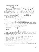
Cd = drag coefficient specified in Figure 1.5.2-2
The area of the structure or element under consideration, At, shall be the solid
area in normal projected elevation, without live load, subject to the following
provisions:
For superstructures with solid parapets, the area of superstructure shall
include the area of the solid windward parapet, but the effect of the
leeward parapet need not be considered.
For superstructures with open parapets, the total load shall be the sum of
the loads for the superstructure, the windward parapet and the leeward
Danang PIIP : Component C – Urban Roads and Bridges
Detailed Design for the Construction of the Southern Link Road
International Inc.(USA)
16
29 December 2011
Design Criteria
parapet considered separately. Where there are more than two parapets,
only those two having the greatest unshielded effect shall be considered.
For truss girder superstructures, the wind force shall be calculated for each
component separately, both windward and leeward, without considering
shielding.
For piers, shielding shall not be considered.
The drag coefficient, Cd, shall be calculated according to the following
methods:
For superstructures with solid elevation, of conventional construction with
bluff edges and without aerodynamically significant re-entrant angles, Cd
shall be derived from Figure 1.5.2-2, where:
b = overall width of bridge between outer faces of parapets (mm)
d = depth of superstructure, including solid parapets if applicable (mm)
For truss girder superstructures, parapets and substructures, the wind force
shall be calculated for each component separately using the values of Cd
from TCVN 2737 – 1995, Table 6, or from any other recognized source
approved by the Owner.
For all other superstructures, Cd shall be determined by wind tunnel
testing.
Figure 1.5.2-2 – Drag Coefficient Cd for Superstructures with Solid Elevation
Danang PIIP : Component C – Urban Roads and Bridges
Detailed Design for the Construction of the Southern Link Road
International Inc.(USA)
17
29 December 2011
Design Criteria
Notes to Figure 1.5.2-2:
1. The values given assume a vertical elevation and a horizontal wind.
2. Where the windward face is inclined to the vertical, the drag coefficient Cd
may be reduced by 0.5% per degree of inclination from the vertical,
subject to a maximum reduction of 30%.
3. Where the windward face consists of a vertical and a sloping part or two
sloping parts inclined at different angles, the wind load shall be derived as
follows:
a) The basic drag coefficient Cd is calculated using the total depth of the
structure.
b) For each non-vertical face, the basic drag coefficient calculated above
is reduced in accordance with Note 2.
c) The total wind load is calculated by applying the appropriate drag
coefficients to the relevant areas.
4. Where a superstructure is superelevated, Cd shall be increased by 3% per
degree of inclination to the horizontal, but not by more than 25%.
5. Where a superstructure is subject to wind inclined at not more than 5o to
the horizontal, Cd shall be increased by 15%. Where the angle of
inclination exceeds 5o, the drag coefficient shall be derived from tests.
6. Where a superstructure is superelevated and also subject to inclined wind,
the drag coefficient shall be the subject of a special investigation.
6.1.2. Longitudinal Wind Load
For piers, abutments, truss girder superstructures and other
superstructure forms which present a significant surface area to wind
loads parallel to the longitudinal centerline of the structure, a
longitudinal wind load shall be considered. The longitudinal wind
loads shall be calculated in a manner similar to those for transverse
wind loads.
For superstructures with solid elevation, a longitudinal wind load
equal to 0.25 times the transverse wind load shall be applied.
Longitudinal and transverse wind loads shall be applied as separate
load cases and, where appropriate, the structure checked for the effect
of intermediate angles of wind by resolution of forces.
Danang PIIP : Component C – Urban Roads and Bridges
Detailed Design for the Construction of the Southern Link Road
International Inc.(USA)
18
29 December 2011
Design Criteria
6.2) Wind Pressure on Vehicles (WL)
When considering the STRENGTH III load combination, the design wind
load shall be applied to both structure and vehicles. Transverse wind load
on vehicles shall be represented by a line load of 1.5 kN/m acting
horizontally, transverse to the longitudinal centerline of the structure and
1800 mm above the roadway. Longitudinal wind load on vehicles shall be
represented by a line load of 0.75 kN/m, acting horizontally, parallel to the
longitudinal centerline of the structure and 1800 mm above the roadway. In
each case the load shall be transmitted to the structure.
Longitudinal and transverse wind loads on vehicles shall be applied as
separate load cases and, where appropriate, the structure checked for the
effect of intermediate angles of wind by resolution of forces.
6.3) Vertical Wind Pressure (PV)
A vertical wind load, PV, shall be taken as acting at the centroid of the
appropriate area, and shall be calculated as:
PV = 0.00045 V2 Av
(kN)
where:
V = design wind velocity (m/s)
Av = plan area of the bridge deck or element for calculation of
vertical wind load (m2)
This load shall be applied only for limit states that do not involve wind on
live load, and only when the direction of wind is taken to be perpendicular
to the longitudinal axis of the bridge. This load shall be applied in
conjunction with the horizontal wind loads.
The above Pv may be used provided the angle of inclination of the wind to
the structure is less than 5 degrees; for inclinations in excess of this, the lift
coefficient shall be determined by testing.
7) Stream Flow (SF)
The effect of flowing water on piers shall be calculated by the following
formulas:
7.1) Longitudinal Direction
The pressure of flowing water acting in the longitudinal direction of
substructure shall be taken as:
Danang PIIP : Component C – Urban Roads and Bridges
Detailed Design for the Construction of the Southern Link Road
International Inc.(USA)
19
29 December 2011
Design Criteria
p 5.4 x10 4 C DV 2
where:
p = pressure of flowing water (MPa)
CD = drag coefficient for piers as specified in Table 1.5.2-5
V = design velocity of water for the design flood in strength and service limit
states and for the check flood in the extreme event limit state (m/s)
= 0.71 m/s (V1% based on hydrological report)
Table 1.5.2-5: Drag Coefficient
Type
semi circular-nosed pier
square-ended pier
debris lodged against the pier
wedged-nosed pier with nose
angle 90° or less
CD
0.70
1.40
1.40
0.80
7.2) Lateral Direction
The lateral, uniformly distributed pressure on a substructure due to water
flowing at angle to the longitudinal axis of the pier shall be taken as:
p 5.14 x10 4 C LV 2
where:
p = lateral pressure (MPa)
CL = lateral drag coefficient for piers as specified in Table 1.5.2-6
Table 1.5.2-6: Lateral Drag Coefficient
Angle between direction of flow
and longitudinal axis of the pier
0°
5°
10°
20°
≥ 30°
CL
0.00
0.50
0.70
0.90
1.00
Danang PIIP : Component C – Urban Roads and Bridges
Detailed Design for the Construction of the Southern Link Road
International Inc.(USA)
20
29 December 2011
Design Criteria
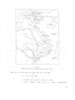
Figure 1.5.2-4: Plan View of Pier Showing Stream Flow Pressure
1.5.3
Loads due to Volumetric Changes
Provisions shall be made for all movements and forces that can occur in the structure
as a result of shrinkage, creep and variations in temperature. Load effects that may
be induced by a restraint to these movements shall be included in the analysis.
Effects due to thermal gradients within the section should also be considered.
1) Temperature Rise or Fall Effect (TRF)
The maximum and minimum average bridge temperatures shall be as specified in
Table 1.5.3-1.The difference between the maximum and minimum average
bridge temperature and the base construction temperature assumed in the design
shall be used to calculate thermal deformation effects.
The temperature ranges given in Table 1.5.3-1 apply to bridge decks with a depth
up to 2m and with 100 mm thickness of surfacing in the case of concrete decks
and 40 mm in the case of steel decks.Where a deeper deck or different surfacing
thickness is used, the temperature ranges should be adjusted accordingly.
Table 1.5.3-1- Bridge Temperature Ranges
Climate Zone
Concrete
superstructure
Concrete deck on
steel girders or
box
Steel deck on steel
girders or box
North of Latitude 16°
N (Hai Van Pass) *
+5°C to +47°C
+1°C to +55°C
-3°C to +63°C
South of Latitude 16°
N (Hai Van Pass)
+10°C to +47°C
+6°C to +55°C
+2°C to +63°C
* Note : For sites north of latitude 16° N and at an elevation above sea level greater than
700m, the minimum temperature in the table shall be reduced by 5°C.
Danang PIIP : Component C – Urban Roads and Bridges
Detailed Design for the Construction of the Southern Link Road
International Inc.(USA)
21
29 December 2011
Design Criteria
In this project, the location is the south from Hai Van Pass and the average
temperature in Danang city is 26°C.
The coefficient of thermal expansion (α) to be used in the analysis are as
follows:
11.7x10⁻⁶/◦C for steel
10.8x10⁻⁶/◦C for normal density concrete
2) Temperature Gradient Effect (TG)
The effects of vertical differential temperature gradients through a bridge
superstructure shall be derived for both positive temperature differential
conditions (top surface hotter) and negative temperature differentials (top surface
cooler).
The vertical temperature gradient in concrete superstructures and steel/concrete
composite superstructures with concrete decks may be taken as shown in Figure
1.5.3-1.Values of T1, T2 and T3 in Figure are given in Table 1.5.3-2 for both
positive and negative temperature differentials. Dimension “A” in the Figure
shall be taken as:
For concrete superstructures that are 400 mm or more in depth – 300 mm
For concrete sections shallower than 400 mm – 100 mm less than the actual
depth
For steel/concrete composite superstructures, the distance “t” shall be taken as
the depth of the concrete deck
For superstructures comprising a steel deck on steel girders or box, temperature
gradients shall be determined be a recognized method approved by the Owner.
The temperature gradients given in Table 1.5.3-2 apply to bridge decks with 100
mm thickness of surfacing. Where a different surfacing thickness is used, the
values should be adjusted accordingly.
Danang PIIP : Component C – Urban Roads and Bridges
Detailed Design for the Construction of the Southern Link Road
International Inc.(USA)
22
29 December 2011