Tài liệu hướng dẫn sử dụng LOGO
Bạn đang xem bản rút gọn của tài liệu. Xem và tải ngay bản đầy đủ của tài liệu tại đây (1.17 MB, 256 trang )
Welcome to LOGO!
Dear Customer,
We thank you for the purchase of LOGO! and congratulate you on
your decision. With the LOGO! you have acquired a logic module
that meets the stringent quality requirements of ISO 9001.
LOGO! can be used in many fields of applications. Due to its high
functionality and yet easy operation the LOGO! offers you highly
efficient economies for almost any application.
LOGO! documentation
This LOGO! Manual contains information relating to the installation, programming and the use of LOGO! 0BA3 Basic devices and
LOGO! 0BA0 expansion modules as well as their down compatibility to the previous Basic devices 0BA0, 0BA1 and 0BA2 (0BAx
are the last four characters of the order number, used to distinguish the module series).
You can find information on wiring the LOGO! in the LOGO! manual and in the product info included with every device. Find supplementary information re programming the LOGO! with the PC in
the Online Help for LOGO!Soft Comfort.
LOGO!Soft Comfort is the programming software for PCs. It runs
under WindowsR, LinuxR, and Mac OS XR and helps you to get
familiarized with your LOGO! and to write, test, print out and archive your programs, independent of the LOGO! .
Guide to the manual
We have divided this manual into 9 chapters:
S
S
S
S
S
S
S
S
S
Working with LOGO!
Installing and wiring the LOGO!
Programming LOGO!
LOGO! Functions
Configuring LOGO!
LOGO! Program Modules
LOGO! Software
Applications
Appendices
LOGO! Manual
A5E00119092-01
i
Welcome to LOGO!
Major changes to previous Basic devices (0BA0 to 0BA2)
S The design of LOGO!Basic versions is improved: all versions
are equipped with 8 inputs and 4 outputs.
S LOGO!Basic is modular: all versions are equipped with an expansion interface.
S LOGO! is a versatile equipment: there is a series of expansion
modules available to you, including, for example, digital modules and an analog module.
New features of the current Basic devices (0BA3)
S
S
S
S
Password protection for the user program.
Program name.
Special ’Softkey’ function.
New menu item “S/W Time” for automatic summertime/wintertime conversion.
S Acknowledgment of the message text in RUN mode.
S Wall mounting is possible.
Additional support
Queries related to your LOGO! can be answered quickly and easily on our website .
ii
LOGO! Manual
A5E00119092-01
Welcome to LOGO!
Safety guidelines
The notes in this user manual are for your own personal safety
and for preventing damage to assets. You should read them carefully and follow the instructions they give you. These instructions
are highlighted by a warning triangle and are marked as follows
according to their danger level:
!
!
!
Danger
Warns that death, serious harm to health or damage to
assets will result if the respective precautionary measures are not taken.
Warning
Warns that death, serious harm to health or damage to
can result if the respective precautionary measures
are not taken.
Caution
Warns that harm to health or damage to assets can
result if the respective precautionary measures are not
taken.
Note
Draws your attention to particularly important information relating to the product and its handling, or to a part
of the documentation requiring your special attention.
!
Warning
LOGO! Manual
A5E00119092-01
Only skilled personnel should be allowed to start and
operate this device. Qualified personnel in the sense of
the information on safety technology in this manual are
persons who are authorized to commission, to ground
and to tag circuits, equipment and systems in accordance with safety regulations and standards.
iii
Welcome to LOGO!
!
Warning
This device must always be used as intended for the
applications described in the catalog and in the technical specifications, and only in combination with non–
Siemens devices or components approved or recommended by Siemens .
Prerequisite for the safe and correct functioning of the
product is its proper transportation, storage, commissioning and installation as well as meticulous operation
and maintenance.
Copyright E Siemens AG 1996 to 2001 All rights reserved
The reproduction, distribution or use of this document or its contents is not permitted without
express written authority. Offenders will be liable for damages. All rights reserved, in
particular in the event of patents being granted or the registration of a utility model or design.
Disclaimer of liability
We have examined the contents of this publication for agreement with the hardware and
software described. Nevertheless, discrepancies cannot be ruled out. Any liability and
warranty for the accuracy of this information is excluded. The data in this manual are
reviewed at regular intervals. Any corrections required are included in the subsequent
editions. Suggestions for improvement are welcomed.
iv
LOGO! Manual
A5E00119092-01
Contents
1
Working with LOGO! . . . . . . . . . . . . .
1
2
Installing and wiring the LOGO! . . .
11
2.1
2.1.1
2.1.2
2.2
2.2.1
2.2.2
2.3
2.3.1
2.3.2
2.3.3
2.4
Structure of the modular LOGO! . . . . . . . . . . . . . . . .
Maximum structure . . . . . . . . . . . . . . . . . . . . . . . . . . . .
Structure with different voltage classes . . . . . . . . . . .
Installing/uninstalling LOGO! . . . . . . . . . . . . . . . . . .
Profile rail mounting . . . . . . . . . . . . . . . . . . . . . . . . . . .
Wall-mounting . . . . . . . . . . . . . . . . . . . . . . . . . . . . . . . .
Wiring the LOGO! . . . . . . . . . . . . . . . . . . . . . . . . . . . . .
Connecting the Power Supply . . . . . . . . . . . . . . . . . . .
Connecting LOGO! inputs Connecting . . . . . . . . . . .
LOGO! Outputs connecting . . . . . . . . . . . . . . . . . . . . .
Switching on the LOGO!/Power return . . . . . . . . . .
13
13
14
15
16
20
22
22
24
29
31
3
Programming LOGO! . . . . . . . . . . . . .
35
3.1
Connectors . . . . . . . . . . . . . . . . . . . . . . . . . . . . . . . . . . .
36
3.2
3.3
3.4
3.5
Blocks and Block Numbers . . . . . . . . . . . . . . . . . . . . .
The way from the Circuit Diagram to LOGO! . . . . .
The 4 Golden Rules for Working with LOGO! . . . .
Overview of the LOGO! Menus . . . . . . . . . . . . . . . . .
39
42
45
47
LOGO! Manual
A5E00119092-01
v
Contents
3.6 Program Input and Start . . . . . . . . . . . . . . . . . . . . . . .
3.6.1 Change to Programming mode . . . . . . . . . . . . . . . . . .
3.6.2 First Program . . . . . . . . . . . . . . . . . . . . . . . . . . . . . . . . .
3.6.3 Editing a Program . . . . . . . . . . . . . . . . . . . . . . . . . . . . .
3.6.4 Assigning a Program Name . . . . . . . . . . . . . . . . . . . .
3.6.5 Password . . . . . . . . . . . . . . . . . . . . . . . . . . . . . . . . . . . .
3.6.6 LOGO! to RUN mode . . . . . . . . . . . . . . . . . . . . . . . . . .
3.6.7 Your Second Program . . . . . . . . . . . . . . . . . . . . . . . . .
3.6.8 Deleting a Block . . . . . . . . . . . . . . . . . . . . . . . . . . . . . .
3.6.9 Deleting Multiple Interconnected Blocks . . . . . . . . . .
3.6.10 Correcting Typing Errors . . . . . . . . . . . . . . . . . . . . . . .
3.6.11 ”?” on the Display . . . . . . . . . . . . . . . . . . . . . . . . . . . . .
3.6.12 Deleting a Program . . . . . . . . . . . . . . . . . . . . . . . . . . . .
3.6.13 Summertime/Wintertime Conversion . . . . . . . . . . . . .
3.7 Memory Space and Size of a Circuit . . . . . . . . . . . . .
48
48
49
51
55
57
61
63
69
70
71
71
72
73
77
4
LOGO! Functions . . . . . . . . . . . . . . . .
81
4.1
Constants and Connectors – Co . . . . . . . . . . . . . . . .
82
4.2 List of basic functions – BF . . . . . . . . . . . . . . . . . . . .
4.2.1 AND (AND) . . . . . . . . . . . . . . . . . . . . . . . . . . . . . . . . . .
4.2.2 Edge-triggered AND . . . . . . . . . . . . . . . . . . . . . . . . . . .
4.2.3 NAND (AND not) . . . . . . . . . . . . . . . . . . . . . . . . . . . . . .
4.2.4 NAND With Edge Evaluation . . . . . . . . . . . . . . . . . . .
4.2.5 OR (OR) . . . . . . . . . . . . . . . . . . . . . . . . . . . . . . . . . . . . .
4.2.6 NOR (OR not) . . . . . . . . . . . . . . . . . . . . . . . . . . . . . . . .
4.2.7 XOR (exclusive OR) . . . . . . . . . . . . . . . . . . . . . . . . . . .
4.2.8 NOT (Negation, Inverter) . . . . . . . . . . . . . . . . . . . . . . .
85
87
87
88
89
89
90
91
91
vi
LOGO! Manual
A5E00119092-01
Contents
4.3 Basics on special functions . . . . . . . . . . . . . . . . . . . .
4.3.1 Designation of the inputs . . . . . . . . . . . . . . . . . . . . . . .
4.3.2 Time Response . . . . . . . . . . . . . . . . . . . . . . . . . . . . . . .
4.3.3 Buffering The Clock . . . . . . . . . . . . . . . . . . . . . . . . . . .
4.3.4 Retentivity . . . . . . . . . . . . . . . . . . . . . . . . . . . . . . . . . . .
4.3.5 Parameter Protection . . . . . . . . . . . . . . . . . . . . . . . . . .
4.3.6 Gain and Offset Calculation With Analog Values . . .
4.4 List of Special Functions – SFr . . . . . . . . . . . . . . . . .
4.4.1 On Delay . . . . . . . . . . . . . . . . . . . . . . . . . . . . . . . . . . . .
4.4.2 Off Delay . . . . . . . . . . . . . . . . . . . . . . . . . . . . . . . . . . . .
4.4.3 On/Off Delay . . . . . . . . . . . . . . . . . . . . . . . . . . . . . . . . .
4.4.4 Retentive On Delay . . . . . . . . . . . . . . . . . . . . . . . . . . .
4.4.5 Latching Relay . . . . . . . . . . . . . . . . . . . . . . . . . . . . . . . .
4.4.6 Pulse Relay . . . . . . . . . . . . . . . . . . . . . . . . . . . . . . . . . .
4.4.7 Wiping Relay – Pulse Output . . . . . . . . . . . . . . . . . . .
4.4.8 Edge–triggered Wiping Relay . . . . . . . . . . . . . . . . . . .
4.4.9 Weekly Timer Switch . . . . . . . . . . . . . . . . . . . . . . . . . .
4.4.10 Yearly Timer Switch . . . . . . . . . . . . . . . . . . . . . . . . . . .
4.4.11 Up/Down Counter . . . . . . . . . . . . . . . . . . . . . . . . . . . . .
4.4.12 Operating Hours Counter . . . . . . . . . . . . . . . . . . . . . .
4.4.13 Symmetric Clock Generator . . . . . . . . . . . . . . . . . . . .
4.4.14 Asynchronous Pulse Generator . . . . . . . . . . . . . . . . .
4.4.15 Random Generator . . . . . . . . . . . . . . . . . . . . . . . . . . . .
4.4.16 Frequency Threshold Trigger . . . . . . . . . . . . . . . . . . .
4.4.17 Analog Threshold Switch . . . . . . . . . . . . . . . . . . . . . . .
4.4.18 Analog Comparator . . . . . . . . . . . . . . . . . . . . . . . . . . .
4.4.19 Stairway Lighting . . . . . . . . . . . . . . . . . . . . . . . . . . . . . .
4.4.20 Multifunctional switch . . . . . . . . . . . . . . . . . . . . . . . . . .
4.4.21 Message Texts . . . . . . . . . . . . . . . . . . . . . . . . . . . . . . .
4.4.22 Softkey . . . . . . . . . . . . . . . . . . . . . . . . . . . . . . . . . . . . . .
LOGO! Manual
A5E00119092-01
92
93
94
95
95
96
96
98
101
103
105
107
109
111
112
114
115
120
122
124
128
130
131
133
135
138
141
143
145
148
vii
Contents
5
Configuring LOGO! . . . . . . . . . . . . . . .
5.1 Switching To Parameter Assignment Mode . . . . . .
5.1.1 Parameter . . . . . . . . . . . . . . . . . . . . . . . . . . . . . . . . . . .
5.1.2 Selecting the Parameters . . . . . . . . . . . . . . . . . . . . . .
5.1.3 Changing the Parameters . . . . . . . . . . . . . . . . . . . . . .
5.2 Setting the Time–of–day and the Date
(LOGO! ... C) . . . . . . . . . . . . . . . . . . . . . . . . . . . . . . . . . .
151
152
153
154
155
158
6
LOGO! Program Modules . . . . . . . . .
159
6.1
6.2
6.3
6.4
Overview of the Modules . . . . . . . . . . . . . . . . . . . . . . .
Removing and Inserting Modules . . . . . . . . . . . . . . .
Copying from the LOGO! to the Module . . . . . . . . .
Copying from the Module to LOGO! . . . . . . . . . . . .
160
161
163
165
7
LOGO! Software . . . . . . . . . . . . . . . . .
7.1
Connecting the LOGO! to a PC . . . . . . . . . . . . . . . . .
viii
167
169
LOGO! Manual
A5E00119092-01
Contents
8
Applications . . . . . . . . . . . . . . . . . . . . .
171
8.1
8.1.1
8.1.2
8.1.3
8.1.4
8.2
8.2.1
8.2.2
8.2.3
8.2.4
8.2.5
8.3
8.3.1
8.3.2
8.4
8.4.1
8.4.2
8.4.3
Staircase or Corridor Lighting . . . . . . . . . . . . . . . . . .
Demands on a Staircase Lighting System . . . . . . . .
Previous Solution . . . . . . . . . . . . . . . . . . . . . . . . . . . . .
Lighting System with LOGO! . . . . . . . . . . . . . . . . . . .
Special Features and Expansion Options . . . . . . . . .
Automatic Door . . . . . . . . . . . . . . . . . . . . . . . . . . . . . . .
Demands on an Automatic Door . . . . . . . . . . . . . . . .
Previous Solution . . . . . . . . . . . . . . . . . . . . . . . . . . . . .
Door Control System with LOGO! . . . . . . . . . . . . . . .
Special Features and Expansion Options . . . . . . . . .
Enhanced solutions with LOGO! 230 RC . . . . . . . . .
Air–conditioning System . . . . . . . . . . . . . . . . . . . . . . .
Demands on an air–conditioning System . . . . . . . . .
Advantages of Using LOGO! . . . . . . . . . . . . . . . . . . .
Industrial Gate . . . . . . . . . . . . . . . . . . . . . . . . . . . . . . . .
Demands on the Gate Control System . . . . . . . . . . .
Previous Solution . . . . . . . . . . . . . . . . . . . . . . . . . . . . .
Wiring the LOGO! solution . . . . . . . . . . . . . . . . . . . . .
172
172
172
173
175
176
176
177
177
180
180
183
183
186
188
188
189
191
Centralized Control and Monitoring of
Several Industrial Gates . . . . . . . . . . . . . . . . . . . . . . . .
8.5.1 Demands on the Gate Control System . . . . . . . . . . .
192
193
8.5
8.6 Luminous rows . . . . . . . . . . . . . . . . . . . . . . . . . . . . . . . .
8.6.1 Demands on the Lighting System . . . . . . . . . . . . . . .
8.6.2 Previous Solution . . . . . . . . . . . . . . . . . . . . . . . . . . . . .
8.6.3 Luminous row control with LOGO! 230 RC . . . . . . .
8.7 Service water pump . . . . . . . . . . . . . . . . . . . . . . . . . . . .
8.7.1 Demands on the control system of a service
water pump . . . . . . . . . . . . . . . . . . . . . . . . . . . . . . . . . .
8.7.2 Previous Solution . . . . . . . . . . . . . . . . . . . . . . . . . . . . .
8.7.3 Service water pump with LOGO! 230 RC . . . . . . . . .
8.7.4 Special Features and Expansion Options . . . . . . . . .
8.8
Further Application options . . . . . . . . . . . . . . . . . . .
LOGO! Manual
A5E00119092-01
196
196
197
198
200
201
201
202
203
204
ix
Contents
A
Technical Data . . . . . . . . . . . . . . . . . . .
A.1
General Technical Data . . . . . . . . . . . . . . . . . . . . . . . .
207
A.2
Technical Data: LOGO! 230... and
LOGO! DM8 230R . . . . . . . . . . . . . . . . . . . . . . . . . . . . . .
209
Technical Data: LOGO! 24... and
LOGO! DM8 24 . . . . . . . . . . . . . . . . . . . . . . . . . . . . . . . .
212
A.5
A.6
A.7
A.8
Technical Data: LOGO! 12/24... and
LOGO! DM8 12/24R . . . . . . . . . . . . . . . . . . . . . . . . . . . .
Technical Data: LOGO! AM 2 . . . . . . . . . . . . . . . . . . .
Technical Data: LOGO!Power 12 V . . . . . . . . . . . . . .
Technical Data: LOGO!Power 24 V . . . . . . . . . . . . . .
Technical Data: LOGO! Contact 24/230 . . . . . . . . . .
215
218
220
222
224
B
Determining the Cycle Time . . . . . . .
225
C
LOGO! without display . . . . . . . . . . .
227
D
LOGO! Menu structure . . . . . . . . . . . .
231
Order Numbers . . . . . . . . . . . . . . . . . . . . . .
235
Abbreviations . . . . . . . . . . . . . . . . . . . . . . . .
237
Index . . . . . . . . . . . . . . . . . . . . . . . . . . . . . . . .
239
A.3
A.4
x
207
LOGO! Manual
A5E00119092-01
1 Working with LOGO!
What is LOGO! ?
LOGO! represents the universal Siemens logic module.
LOGO! integrates
S Controls
S An operating and display unit
S Power supply
S Interface for expansion modules
S An interface for program modules and a PC cable
S Ready–to–use basic functions that are often required in
day–to–day operation, e.g. functions for on/off delays,
current impulse relays and Softkey
S Time switch
S Binary markers
S Inputs and outputs according to the device type
What can LOGO! do ?
LOGO! offers solutions for domestic and installation engineering (e.g. for stairway lighting, external lighting, sun
blinds, shutters, shop window lighting etc.), switch cabinet
engineering and mechanical and apparatus engineering
(e.g. for gate control systems, ventilation systems, or rainwater pumps etc.).
LOGO! can also be implemented for special control systems in conservatories or greenhouses, for control signal
processing and, by connecting a communication module
(e.g. ASi) for distributed local controlling of machines and
processes.
Special versions without operator and display unit are available for series production applications in small machine,
apparatus, switch control and installation engineering.
LOGO! Manual
A5E00119092-01
1
Working with LOGO!
Which new types of equipment are now available?
LOGO! Basically, there are two voltage classes:
S Class 1 < 24 V, that is, 12 V DC, 24 V DC, 24 V AC
Class 2 > 24 V, that is, 115...240 V AC/DC
in versions:
S With display: 8 inputs and 4 outputs.
S Without display: 8 inputs and 4 outputs.
Each version is integrated in 4 units. It is equipped with an
expansion interface and offers you 30 ready–to–us basic
and special functions for creating your program.
Which new expansion modules are now available?
S The LOGO! digital module is available for 12 V DC,
24 V DC and 115...240 V AC/DC, with 4 I/Os.
S The LOGO! analog module is available for 12 V DC and
24 V DC, with 2 inputs.
S The LOGO! Communication module, e.g. the function
module ASi (AS Interface bus system). This module is
described in a separate documentation.
The digital/analog modules are integrated in 2 units. Each
one has two expansion interfaces for connecting additional
modules.
Which type of equipment is obsolete?
S All versions with 6 inputs.
S A long variant with 12 inputs and 8 outputs
S The bus version with 12 inputs and 8 outputs.
The modular strikers of LOGO! replace this type of equipment.
It’s your choice
The different basic versions and expansion modules offer
structures and precise adaptation to you specific tasks.
LOGO! provides solutions ranging from the small domestic
installation through small automation tasks to extensive
tasks integrating a bus system (e.g. the AS interface).
2
LOGO! Manual
A5E00119092-01
Working with LOGO!
Note
Every basic LOGO! unit can be expanded with expansion
modules of the same voltage class. Mechanical encoding
(pin in the housing) prevents interconnection of devices of
different voltage classes.
Exception: The left interface of the analog module or
communication module is separated from potential.
This means that these expansion modules can be connected to devices of a different voltage class. See also
Chapter 2.1 ’Structure of the modular LOGO!’.
Regardless of the number of modules connected to the
LOGO!, the following I/O and memory bits are available: I1
to I24, AI1 to AI8, Q1 to Q16 And M1 to M8.
LOGO! Manual
A5E00119092-01
3
Working with LOGO!
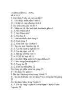
How the LOGO! is structured
2
10
1
8
I1 I2 I3 I4
I5 I6 I7 I8
LOGO! Basic (e.g.: 230 RC)
4
L1 N
4
90
35
6
5
1
Q1
2
1
Q2
2
1
Q3
2
1
Q4
2
3
72
55
2
9
9
8
10
1
8
11
(e.g.: DM8 230R)
7
RUN/STOP
1
Q1
2
1
Q2
1 Q3 2
90
35
LOGO! Expansion module
4
L1 N I1 I2 I3 I4
2
1Q4 2
3
53
36
1
Power supply
2
Inputs
3
Outputs
4
Module slot with
cover
4
5
Control panel
(not with RCo)
8
Expansion interface
6
LCD
(not with RCo)
9
7
Status display RUN/
STOP
Mechanical coding –
Pins
Mechanical coding
sockets
Slide
10
11
LOGO! Manual
A5E00119092-01
Working with LOGO!
2
10
1
8
4
LOGO! Basic (e.g.: 12/24 RC)
L+ M I1 I2 I3 I4 I5 I6 I7 I8
4
90
35
6
5
1
Q1
2
1
Q2
2
1
Q3
2
1
Q4
2
3
72
55
2
9
9
8
10
1
8
11
(e.g.: DM8 12/24R)
7
RUN/STOP
1
2
Q1
1
1Q3 2
Q2
90
35
LOGO! Expansion module
4
L+ M I1 I2 I3 I4
2
1 Q4 2
3
53
36
1
Power supply
2
Inputs
3
Outputs
4
Module slot with
cover
LOGO! Manual
A5E00119092-01
5
Control panel
(not with RCo)
8
Expansion interface
6
LCD
(not with RCo)
9
Mechanical coding
pins
7
Status display RUN/
STOP
10
Mechanical coding
sockets
11
Slide
5
Working with LOGO!
LOGO! AM2
9
10
1
9
8
L+ M
4
L+ M
8
11
90
RUN/STOP
35
7
12
PE
INPUT 2x(0..10V/0..20 mA)
I1 M1 U1 I2 M2 U2
2
53
36
1
Power supply
2
Inputs
7
Status display RUN/
STOP
Expansion interface
8
6
9
Mechanical coding
pins
10
Mechanical coding
sockets
11
12
Grounding terminal for
connecting ground and
shielding of the analog
measuring line.
Slide
LOGO! Manual
A5E00119092-01
Working with LOGO!
How to recognize which LOGO! model you have
The LOGO! identifier informs of various properties:
S 12: 12 V DC version
S 24: 24 V DC version
S 230: 115...240 V AC version
S R: Relay outputs (without R: transistor outputs)
S C: Integrated Weekly timer switch
S o: Version without display
S DM: Digital module
S AM: Analog module
S FM: Function module (e.g. ASi)
Symbols
Variants with display are equipped with 8 inputs and 4 outputs
Variants without display are equipped with 8 inputs and 4
outputs
The digital module is equipped with 4 digital inputs and 4
digital outputs
The analog module is equipped with 2 analog inputs
–+
Function module (e.g. ASi) with 4 virtual inputs and 4
virtual outputs
LOGO! Manual
A5E00119092-01
7
Working with LOGO!
Variants
LOGO! is available in the following variants:
Symbol
Designation
Supply
voltage
Inputs
Outputs
Properties
LOGO! 12/24RC
12/24 V
DC
8 Digital*
4 Relays
230 V x 10
A
LOGO! 24
24 V DC
8 Digital*
4 Transistor
24 V x 0.3 A
LOGO! 24RC
24 V AC
8 Digital
4 Relays
230 Vx10 A
LOGO! 230RC #
115...240 V
AC/DC
8 Digital
4 Relays
230 Vx10 A
LOGO! 12/24RCo
12/24 V
DC
8 Digital*
4 Relays
230 Vx10 A
no display
24 V AC
8 Digital
4 Relays
230 Vx10 A
no display
4 Relays
230 Vx10 A
no display
LOGO! 24RCo
LOGO! 230RCo #
115...240 V
AC/DC
8 Digital
no clock
no keyboard
no keyboard
no keyboard
*: alternatively, 2 analog inputs (0...10V) and 2 fast inputs can be used.
#: 230 V AC variants: Inputs in two groups of 4. Within a group only the same phase,
between groups different phases are possible.
Expansion module
The LOGO! can be connected to the following expansion
modules:
Symbol
Designation
Supply voltage
Inputs
LOGO! DM 8 12/24
R
12/24 V DC
4 Digital
LOGO! DM 8 24
24 V DC
4 Digital
Outputs
4 Relays (3)
4 Transistors
(1)
LOGO! DM 8 230R
115...240 V AC/DC
4 Digital
LOGO! AM 2
12/24 V DC
2 Analog
0–10 V or
0–20 mA (2)
4 Relays (3)
none
(1): no different phases allowed within the inputs.
(2): 0–10 V, 0–20 mA connection is optional.
(3): The maximum sum switching power across all four relays is 20 A.
8
LOGO! Manual
A5E00119092-01
Working with LOGO!
Certification, recognition and approval
LOGO! is certified according to UL, CSA and FM.
S UL listing mark
Underwriters Laboratories (UL) to
UL 508 standard, file no. 116536
S CSA–Certification–Mark
Canadian Standard Association (CSA) to
Standard C22.2 No. 142, File No. LR 48323
S FM certification
Factory Mutual (FM) Approval to
Standard Class Number 3611,
– Class I, Division 2, Group A, B, C, D
– Class I, Zone 2, Group IIC
!
Warning
Personal injury and material damage may be
incurred.
In potentially explosive areas, personal injury or
property damage can result if you withdraw any
connectors while the system is in operation.
Always switch off the power supply for the
LOGO! and its components before you disconnect any connectors.
LOGO! carries CE marking, complies with VDE 0631 and
IEC 61131–2 standard and has interference suppression to
EN 55011 (limit class B, class A for ASi bus operation).
Shipbuilding certification has been requested.
S ABS – American Bureau of Shipping
S BV – Bureau Veritas
S DNV – Det Norske Veritas
S GL – Germanischer Lloyd
S LRS – Lloyds Register of Shipping
S PRS – Polski Rejestr Statków
LOGO! Manual
A5E00119092-01
9
Working with LOGO!
LOGO! can therefore be used both in industry and domestic areas.
C Tick Mark (Australia)
The products carrying the label shown at the side are compliant with AS/NZL 2064:1997 (Class A) standard
10
LOGO! Manual
A5E00119092-01
2 Installing and wiring the LOGO!
General Guidelines
When mounting and wiring your LOGO! you should observe the following guidelines:
S When wiring the LOGO! ensure you are conforming with
current rules and standards. You should also heed any
national and regional regulations when installing and
operating the devices. Contact the relevant authorities
to find out the standards and regulations that apply in
your specific case.
S Use wires with the appropriate cross–section for the
amount of current involved. LOGO! can be wired using
cables with a conductor cross–section of 1.5 mm2 and
2.5 mm2, refer to Chapter 2.3.
S Don’t screw the connectors too tightly. Maximum torque:
0.5 N/m, refer to Chapter 2.3.
S Keep wiring distances as short as possible. If longer
wires are necessary, a shielded cable should be used.
Arrange you wires in pairs: one neutral conductor with
one phase conductor or one signal line.
S Keep separate:
– AC circuits
– High–voltage DC circuits with fast switching cycles
– Low voltage signal wiring.
S Ensure that the wires have the required strain relief.
S Provide suitable overvoltage protection for wires that
could be vulnerable to lightning.
LOGO! Manual
A5E00119092-01
11
Installing and wiring the LOGO!
S Do not connect an external power supply to an output
load parallel to a DC output. This can result in reverse
current at the output unless you have a diode or a similar block in your configuration.
Note
LOGO! must always be mounted and wired by skilled personnel who are familiar and follow the general rules of the
technology and the respective current rules and standards.
12
LOGO! Manual
A5E00119092-01
Installing and wiring the LOGO!
2.1 Structure of the modular LOGO!
2.1.1 Maximum structure
Maximum structure LOGO! with analog inputs
(LOGO! 12/24 RC/RCo and LOGO! 24)
LOGO! Basic, 4 digital modules and 3 analog modules
I1......I6
AI1 , AI2 I9...I12
LOGO! Basic
I13...I16 I17...I20 I21...I24
LOGO! LOGO! LOGO! LOGO! LOGO! LOGO! LOGO!
DM8
DM8
DM8
DM8
AM2
AM2
AM2
AI3 , AI4 AI5 , AI6 AI7 , AI8
Tip
When using inputs I7 / AI1 and I8 / AI2 as analog inputs,
that is, AI1 and AI2, you should avoid to use them as digital
inputs I7/I8 also.
Maximum structure of LOGO! without analog inputs
(LOGO! 24 RC/RCo and LOGO! 230 RC/RCo)
LOGO! Basic, 4 digital modules and 4 analog modules
I1 . . . . . . . . . . . I8
I9...I12
I13...I16 I17...I20 I21...I24
LOGO! basic
LOGO! LOGO! LOGO! LOGO! LOGO! LOGO! LOGO! LOGO!
DM8
DM8
DM8
DM8
AM2
AM2
AM2
AM2
AI1 , AI2 AI3 , AI4 AI5 , AI6 AI7 , AI8
Fast/optimal communication
In order to achieve an optimal and fast communication between LOGO! Basic and the various modules, we recommend the structure “Digital modules first, then the analog
modules” (example above).
LOGO! Manual
A5E00119092-01
13
Installing and wiring the LOGO!
2.1.2 Structure with different voltage classes
Since the potential of the left analog module interface
(AM2, 12/24 V DC) is separated from the right one, you
can connect it to all LOGO! Basic versions.
The potential of expansion modules arranged to the right of
the analog module is separated from LOGO! Basic.
It is therefore possible to connect an expansion module of
a different voltage class as LOGO! Basic at the right side
of an analog module.
Example:
LOGO! 230...
LOGO! LOGO! LOGO! LOGO! LOGO! LOGO! LOGO!
DM8
AM2
DM8 24 AM2
DM8
AM2
DM8 24
230R
12/24 R
The potential of an analog module is separated
14
LOGO! Manual
A5E00119092-01
Installing and wiring the LOGO!
2.2 Installing/uninstalling LOGO!
Dimensions
LOGO!’s installation dimensions are compliant with
DIN 43880.
LOGO! can be snap–mounted on a 35 mm DIN EN 50022
profile rail or mounted on the wall.
Width of LOGO!:
S LOGO! Basic has a width of 72 mm, corresponding to 4
unit segments.
S The width of LOGO! expansion modules is 36 mm, corresponding to 2 unit segments.
Note
We shall illustrate mounting and removal in a graphic overview for a LOGO! 230 RC and a digital module. The
shown methods also apply for all other LOGO! basic variants and expansion modules.
!
Warning
LOGO! Manual
A5E00119092-01
Expansion modules must only be “Extracted” and
“Plugged” after power is switched off.
15