5 chapter 5 1 output compare
Bạn đang xem bản rút gọn của tài liệu. Xem và tải ngay bản đầy đủ của tài liệu tại đây (1.88 MB, 17 trang )
MICROCONTROLLERS
CHAPTER 5
OUTPUT COMPARE MODULE
Dr. Vo Tuong Quan
HCMUT - 2011
OUTPUT COMPARE
What is Output Compare?
- Compare the value of the time base counter with the value of
one or two compare registers depending on the Operation mode
selected.
- It is able to generate a single output pulse or a sequence of
output pulses when the compared values match generate
interrupts on compare match events.
Several modes of operation selectable by using control bits
OCM<2:0> (OCXCON<2:0>):
1. Single compare match mode
2. Dual compare match mode generating either one output
pulse or a sequence of output pulses,
3. Pulse Width Modulation (PWM) mode.
2
2011 – Vo Tuong Quan
OUTPUT COMPARE
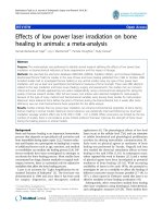
Functional
diagram of
output
compare
module
3
2011 – Vo Tuong Quan
OUTPUT COMPARE
Single compare match mode
- When control bits OCM<2:0> are set to 001, 010, or 011, the
ouput compare module is set to the Single compare match
mode.
- The value loaded in the compare register OCxR is compared
with time base counter TMR2 or TMR3.
At the OCx output pin one of the following situations is
possible:
• OCx pin is high, initial state is low, and interrupt is generated
• OCx pin is low, initial state is high, and interrupt is generated
• State of OCx pin toggles and interrupt is generated.
4
2011 – Vo Tuong Quan
OUTPUT COMPARE
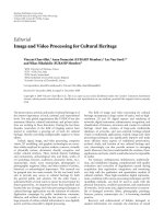
Single compare match, pin ocx driven high
Control bits OCM<2:0> are set to 001.
Time base counter (TMR2 or TMR3) should be selected
Timing diagram of the single compare mode, set OCx high on compare match event
5
2011 – Vo Tuong Quan
OUTPUT COMPARE
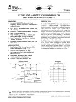
Single compare match, pin OCx driven low
Control bits OCM<2:0> are set to 010.
Time base counter (TMR2 or TMR3) should be enabled
Timing diagram of the single compare mode, set OCx low on compare match event
6
2011 – Vo Tuong Quan
OUTPUT COMPARE
Single compare match, pin ocx toggles
Control bits OCM<2:0> areset to 011.
Time base counter (TMR2 or TMR3) should be enabled
Timing diagrams of the single compare mode, toggle output on compare match
7
event when timer register PRy>OCxR
2011 – Vo Tuong Quan
OUTPUT COMPARE
Timing diagrams of the single compare mode, toggle output on compare
match event when timer register PRy=OCxR
8
2011 – Vo Tuong Quan
OUTPUT COMPARE
Dual compare match mode, single output pulse at pin ocx
Control bits OCM<2:0> are set to 100 the output compare
module is configured for the dual compare match (OCxR and
OCxRS registers)
Timing diagram of the
operation of the output
compare module in the
dual compare match
mode, single pulse at
the output pin OCx
9
2011 – Vo Tuong Quan
OUTPUT COMPARE
Dual compare match mode, sequence of output pulses at pin
ocx
Control bits OCM<2:0> are set to 101 the output compare
module is configured for the dual compare match (OCxR and
OCxRS registers) a sequence of output pulses is generated at
the output OCx pin
10
2011 – Vo Tuong Quan
OUTPUT COMPARE
Timing diagram of the operation in the dual compare match mode, pulse
sequence at the output pin OCx
2011 – Vo Tuong Quan
11
OUTPUT COMPARE
The pulse width modulation (pwm) mode
Control bits OCM<2:0> are set to the values 110 or 111
Configuring the output compare module for PWM mode
1. Set the PWM period by writing to the selected timer period
register, PRy.
2. Set the PWM duty cycle by writing to the OCxRS register.
3. Write the OCxR register with the initial duty cycle.
4. Enable interrupts for the selected timer.
5. Configure the output compare module for one of two PWM
operation modes by writing 100 to control bits OCM<2:0>
(OCxCON<2:0>).
6. Set the TMRy prescale value and enable the selected time
base.
12
2011 – Vo Tuong Quan
OUTPUT COMPARE
Timing diagram of the PWM mode of the output compare module
13
2011 – Vo Tuong Quan
OUTPUT COMPARE
Example
14
2011 – Vo Tuong Quan
OUTPUT COMPARE
15
2011 – Vo Tuong Quan
OUTPUT COMPARE
OCSIDL – output compare stop bit in IDLE state (OCSIDL=0 the
module is active in IDLE state, OCSIDL=1 the module in inactive
in IDLE state)
OCFLT – PWM FAULT state bit (OCFLT=0 no FAULT occured,
OCFLT=1 FAULT occured, hardware reset only)
OCTSEL – Output Compare timer select bit (OCTSEL=0 TMR2
selected, OCTSEL=1 TMR3 selected)
16
2011 – Vo Tuong Quan
OUTPUT COMPARE
OCM <2:0> - mode select bit of the Output Compare Module
000 – Output Compare Module disabled
001 - Single compare match mode, pin OCx driven high
010 - Single compare match mode, pin OCx driven low
011 - Single compare match mode, pin OCx toggles
100 - Dual compare match mode, single output pulse at pin
OCx
101 - Dual compare match mode, sequence of output pulses
at pin OCx
110 - PWM mode without fault protection input
111 - PWM mode with fault protection input
17
2011 – Vo Tuong Quan