Design of a Charge Controller Circuit.pdf
Bạn đang xem bản rút gọn của tài liệu. Xem và tải ngay bản đầy đủ của tài liệu tại đây (2.01 MB, 70 trang )
Design of a Charge Controller Circuit
with Maximum Power Point Tracker
(MPPT) for Photovoltaic System
A Thesis submitted to the
Dept. of Electrical & Electronic Engineering, BRAC University in
partial fulfillment of the requirements for the Bachelor of Science
degree in Electrical & Electronic Engineering
Shusmita Rahman
Nadia Sultana Oni
Quazi Abdullah Ibn Masud
10321065
10321060
10221074
December 15, 2012
Declaration
We do hereby declare that the thesis titled “Design of A battery charge controller with
maximum power point tracker (MPPT) for solar home system” submitted to the
Department of Electrical and Electronics Engineering of BRAC University in partial
fulfillment of the Bachelor of Science in Electrical and Electronics Engineering. This is
our original work and was not submitted elsewhere for the award of any other degree or
any other publication.
Date: 15.12.2012
Supervisor
Dr. Mossaddekur Rahman
Shusmita Rahman
10321065
Nadia Sultana Oni
10321060
Quazi Abdullah Ibn Masud
10221074
Acknowledgement
We would firstly like to acknowledge our supervisor, Dr. Mossaddequr Rahman. We are
grateful to him for his guidance and kind advice. He helped us by giving various ideas
and taught many basics about solar cells and power electronics. Without his help we
would not have been possible for us to implement and present this project.
We are indebted to Mrs. Amina Abedin for her guidance in preparing the simulations.
Also, we would like to thank Jonayet Hossain for his support in software development.
We are also grateful to faculty memebrs Rachaen Mahfuz Haque and Syed Sakib. We are
thankful to Marzuq Rahman, Asad Bhai of CARG and Raktim Kumar Mondol for their
patience and understanding.
Finally, we would like to thank our respective families for their constant encouragement
and support.
I
Abstract
This thesis, aim to design and simulation of a simple but effective charge controller with
maximum power point tracker for photovoltaic system. It provides theoretical studies of
photovoltaic systems and modeling techniques using equivalent electric circuits. As, the
system employs the maximum power point tracker (MPPT), it is consists of various
MPPT algorithms and control methods. P-Spice and MATLAB simulations verify the
DC-DC converter design and hardware implementation. The results validate that MPPT
can significantly increase the efficiency and the performance of PV.
II
Table of Contents
Acknowledgement………………………………………………………………....I
Abstract……………………………………………………………………………II
Table of content list………………………………………………………………III
Table list……………………………………………………………………….......IV
Figure list…………………………………………………………………………..IV
1.
INTRODUCTION………………………………………………………….....1
1.1
1.2
2.
System description……………………………………………………2
Thesis organization…………………………………………………...6
SOLAR CELLS AND THEIR CHARECTERISTICS………….…………..8
2.1
2.2
2.3
2.4
2.5
2.6
2.7
Introduction……………………………………………………………8
Structure of photovoltaic cell………………………………………….8
Photovoltaic modules/ array…………………………………………..10
Photovoltaic cell model……………………………………………….11
I-curve with load resistor……………………………………………...15
Effect of solar irradiance on MPP…………………………………......18
Effect of varying temperature on MPP………………………………...20
MAXIMUM POWER POINT TRACKER (MPPT)………………………23
3.
Introduction………………………………………...............................23
Maximum power point tracking ……………………………………...23
Methods of MPPT algorithms…………………………………….......24
Constant voltage method……………………………………………...24
Open Circuit Voltage method………………………………………....25
Short Circuit Current………………………………………………….25
Incremental Conductance method…………………………………….26
Perturb and Observe method………………………………………….29
Techniques for minimization……………………………………...........33
Control technique………………………………………………..…….33
3.1
3.2
3.3
3.3.1
3.3.2
3.3.3
3.3.4
3.3.5
3.4
3.
4.
4.1
DC-DC CONVERTER………………………………………………………….35
Introduction……………………………………………………………..35
III
4.2
4.3
4.3.1
4.3.2
4.4
4.4.1
4.4.2
4.5
4.5.1
5
Topology………………………………………………………………..35
Buck-boost converter……………………………………………….......37
Continuous conduction mode..................................................................38
Discontinuous conduction mode………………………………………..39
Sepic converter………………………………………………………….40
Continuous mode.....................................................................................40
Discontinuous mode…………………………………………………….42
Cuk DC-DC converter…………………………………………………..43
Circuit Description and Operation……………………………………...43
THE PROPOSED CHARGE CONTROLLER ………………………….....53
5.1
5.2
5.3
5.4
5.5
6.
Microcontroller and Voltage Regulator…………………………………..53
Analog to Digital Conversion (ADC)…………………………………….54
Pulse Width Modulation………………………………………………….56
Battery Discharging……………………………………………………….57
Design Functions………………………………………………………….58
CONCLUSION
6.1
6.2
Summary…………………………………………………………………..61
Concluding remarks..............................................................................…...62
References………………………………………………………………………………63
Table List
Table
Table 2.1
Table 3.1
Table 4.1
Page
Conditions for MATLAB simulation…………………………………..13
P&O method’s efficiency during several conditions……………...........32
Table for varying duty cycle of Cuk converter…………………………52
Figure List
Figures
Figure: 1.1
Figure: 2.1
Figure 2.2:
Figure: 2.3
Figure: 2.4
Figure: 2.5
Figure: 2.6
Page
Block Diagram of the System…………………………………………......2
p-n junction of the PV cell………………………………………………..9
(a) PV cell, (b) PV module, (c) PV array…...…………………………….11
PV cell with its equivalent electric circuit………………………………..12
(a) Short circuit current and (b) Open circuit Voltage……….…...………12
I-V and P-V characteristic of a PV cell…………. ………………………14
PV Module is directly connected to a (variable) resistive load…………..15
IV
Figure: 2.7
Figure: 2.8
Figure 2.9:
Figure: 2.10
Figure: 2.11
Figure: 3.1
Figure: 3.2
Figure: 3.3
Figure: 3.4
Figure: 4.1
Figure: 4.2
Figure: 4.3
Figure: 4.4
Figure: 4.5
Figure: 4.6
Figure: 4.7
Figure: 4.8
Figure: 4.9
Figure: 4.10
Figure: 4.11
Figure: 4.12
Figure: 4.13
Figure: 4.14
Figure: 4.15
Figure: 4.16
Figure: 4.17
Figure: 5.1
Figure: 5.2
Figure: 5.3
Figure: 5.4
Figure: 5.5
Figure: 5.6
Figure: 5.7
I-V curve for difference resistive load…………………………………...16
PV with Load………………………………….………………………….17
I-V curve with different irradiance………………………………….…....19
P-V curves with different irradiance……..………………………………19
I-V curve for varying temperature………….…………………………….21
P-V curve and IncCond algorithm………………………………………..27
The Flowchart of IncCond method………………………………………28
Output power using P&O algorithm………..……………………………29
Perturb and Observe algorithm flow chart……………………………….31
Basic schematic of buck-boost converter…………….………………….37
Continuous mode operation (buck-boost) converter………………….....38
Discontinuous mode operations. (buck-boost) converter........... …...........39
Diagram for a basic SEPIC converter…………………………………....40
Switch Close (SEPIC converter)…...…………………………………….41
Switch Open (SEPIC converter)………………………………………….42
Diagram of a Cuk circuit………………………………………………....44
Switch Off (Cuk circuit)………………………………………………….44
Switch On (Cuk circuit)......................................................................…...45
Variation of Inductor (L1/L2) size with Frequency………………………48
Variation of C1 size with frequency ……………………………………..48
Variation of C2 size with frequency……………………………………...48
Variations in Output Voltage with Frequency…………………………...49
Curve for Vo-D, obtained by P-Spice Simulation………………………..50
P-Spice Cuk Circuit……………………………………………………...50
Simulated Output Voltages……………………………………………...51
Curve for Vo-D, obtained by hardware implementation…………………52
Voltage Regulator (LM 7805) connected to the RESET (pin 1)………....54
Voltage sensing circuit diagram..........................................................…...55
Current sensing circuit diagram……………….……………………….....56
Switching operation of the charging process from the panel to the battery
By using cuk converter…………………………………………………...57
Relay coil……………..………………………………………………….58
Battery discharging operation of the circuit.......................................…....58
Charge controller design schematic………………………………...…….59
V
Chapter 1
Introduction
Solar energy is one of the most important renewable energy sources that have been gaining
increased attention in recent years. Solar energy is plentiful; it has the greatest availability
compared to other energy sources. The amount of energy supplied to the earth in one day by the
sun is sufficient to power the total energy needs of the earth for one year. Solar energy is clean
and free of emissions, since it does not produce pollutants or by-products harmful to nature. The
conversion of solar energy into electrical energy has many application fields.
Solar to electrical energy conversion can be done in two ways: solar thermal and solar
photovoltaic. Solar thermal is similar to conventional AC electricity generation by steam turbine
excepting that instead of fossil fuel; heat extracted from concentrated solar ray is used to produce
steam and apart is stored in thermally insulated tanks for using during intermittency of sunshine
or night time. Solar photovoltaic use cells made of silicon or certain types of semiconductor
materials which convert the light energy absorbed from incident sunshine into DC electricity. To
make up for intermittency and night time storage of the generated electricity into battery is
needed.
Recently, research and development of low cost flat-panel solar panels, thin-film devices,
concentrator systems, and many innovative concepts have increased. In the near future, the costs
of small solar-power modular units and solar-power plants will be economically feasible for
large-scale production and use of solar energy.
In this paper we have presented the photovoltaic solar panel’s operation. The foremost way to
increase the efficiency of a solar panel is to use a Maximum Power point Tracker (MPPT), a
power electronic device that significantly increases the system efficiency. By using it the system
operates at the Maximum Power Point (MPP) and produces its maximum power output. Thus, an
MPPT maximizes the array efficiency, thereby reducing the overall system cost.
1
In addition, we attempt to design the MPPT by using the algorithm of a selected MPPT method
which is “Perturb and Observe” and implement it by using a DC- DC Converter. We have found
various types of DC-DC converter. Among them we have selected the most suitable converter
which is “CUK” converter, for our design.
PV generation systems generally use a microcontroller based charge controller connected to a
battery and the load. A charge controller is used to maintain the proper charging voltage on the
batteries. As the input voltage from the solar array, the charge controller regulates the charge to
the batteries preventing any overcharging. So a good, solid and reliable PV charge controller is a
key component of any PV battery charging system to achieve systems maximum efficiency.
Whereas microcontroller based designs are able to provide more intelligent control and thus
increases the efficiency of the system.
1.1 System Description
DC-DC
Converter
PV
Array
V Sensor
V Sensor
Battery
I Sensor
I Sensor
Power
Calculation
PWM Charge
Controller
MPPT
Algorithm
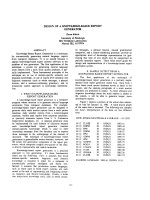
Figure: 1.1 Block Diagram of the System
2
A detailed block diagram of the system is shown in Figure: 1.1 which consists of following
major components:
a) Solar panel
b) Battery
c) Charge Controller
d) Maximum Power Point Tracker
e) DC-DC converter
A brief description of each of the system components is given below,
a) Solar Panel
A solar panel is a packaged connected assembly of photovoltaic cells. The solar panel can be
used as a component of a larger photovoltaic system to generate and supply electricity in
commercial and residential applications.
Solar panels use light energy photon from the sun to generate electricity through the photovoltaic
effect. The majority of modules use wafer based cells or thin film cells based on non-magnetic
conductive transition metals, telluride or silicon. Electrical connections are made in series to
achieve a desired output voltage and or in parallel to provide a desired current capability. The
conducting wires that take the current off the panels may contain silver, copper or other nonmagnetic conductive transition metals. The cells must be connected electrically to one another
and to the rest of the system. Each panel is rated by its DC output power under standard test
conditions, and typically ranges from 100 to 320 watts.
Depending on construction, photovoltaic panels can produce electricity from a range of light
frequencies, but usually cannot cover the entire solar range (specifically, ultraviolet and low or
diffused light). Hence, much of the incident sun light energy is wasted by solar panels, and they
can give far higher efficiencies if illuminated with monochromatic light.
The advantages of solar panels are,
They are the most readily available solar technology.
They can last a lifetime.
3
They are required little maintenance.
They operate best on bright days with little or no obstruction to incident sunlight.
b) Battery
In stand-alone photovoltaic system, the electrical energy produced by the PV array cannot
always be used when it is produced because the demand for energy does not always coincide
with its production. Electrical storage batteries are commonly used in PV system. The primary
functions of a storage battery in a PV system are:
1) Energy Storage Capacity and Autonomy: to store electrical energy when it is produced by
the PV array and to supply energy to electrical loads as needed or on demand.
2) Voltage and Current Stabilization: to supply power to electrical loads at stable voltages
and currents, by suppressing or smoothing out transients that may occur in PV system.
3) Supply Surge Currents: to supply surge or high peak operating currents to electrical loads
or appliances.
c) Charge Controller
A charge controller or charge regulator limits the rate at which electric current is added to or
drawn from electric batteries. It prevents overcharging and may prevent against overvoltage,
which can reduce battery performance or lifespan, and may pose a safety risk. It may also
prevent completely draining ("deep discharging") a battery, or perform controlled discharges,
depending on the battery technology, to protect battery life.
In simple words, Solar Charge controller is a device, which controls the battery charging from
solar cell and also controls the battery drain by load. The simple Solar Charge controller checks
the battery whether it requires charging and if yes it checks the availability of solar power and
starts charging the battery. Whenever controller found that the battery has reached the full
charging voltage levels, it then stops the charging from solar cell. On the other hand, when it
found no solar power available then it assumes that it is night time and switch on the load. It
4
keeps on the load until the battery reached to its minimum voltage levels to prevent the battery
dip-discharge. Simultaneously Charge controller also gives the indications like battery dipdischarge, load on, charging on etc.
In this thesis we are using microcontroller based charge controller. Microcontroller is a kind of
miniature computer containing a processor core, memory, and programmable input/output
peripherals. The Functions of a microcontroller in charge controller are:
Measures Solar Cell Voltage.
Measures Battery Voltage.
Decides when to start battery charging.
Decides when to stop battery charging.
Decides when to switch on the load.
Decides when to switch odd the load.
Most importantly in this thesis, microcontroller also tracks the MPP of the output power.
d) Maximum Power Point Tracker
The maximum power point tracker (MPPT) is now prevalent in grid-tied PV power system and is
becoming more popular in stand-alone systems. MPPT is a power electronic device
interconnecting a PV power source and a load, maximizes the power output from a PV module
or array with varying operating conditions, and therefore maximizes the system efficiency.
MPPT is made up with a switch-mode DC-DC converter and a controller. For grid-tied systems,
a switch-mode inverter sometimes fills the role of MPPT. Otherwise, it is combined with a DCDC converter that performs the MPPT function.
This thesis, therefore, chooses a method Perturb and Observe algorithm for digital control for
MPPT. The design and simulations of MPPT will be done on the premise that is going to be built
with a microcontroller.
5
e) DC-DC Converter
DC-DC converters are power electronic circuits that convert a dc voltage to a different dc
voltage level, often providing a regulated output.
The key ingredient of MPPT hardware is a switch-mode DC-DC converter. It is widely used in
DC power supplies and DC motor drives for the purpose of converting unregulated DC input into
a controlled DC output at a desired voltage level. MPPT uses the same converter for a different
purpose, regulating the input voltage at the PV MPP and providing load matching for the
maximum power transfer.
There are a number of different topologies for DC-DC converters. In this thesis we are using
CUK dc-dc converter as it is obtained by using the duality principle on the circuit of a buckboost converter.
MPPT is one of many applications of power electronics, and it is a relatively new area. This
thesis investigates it in detail and provides better explanations. In order to understand and design
MPPT, it is necessary to have a good understanding of the behaviors of PV. The thesis facilitates
it using MATLAB models of PV cell and module. The other things such as DC-DC converter,
microcontroller based charge controller are also explained elaborately.
1.2 Thesis Organization:
The thesis is organized in an order such as to provide the readers with a general understanding of
the different components present in the photovoltaic battery charging system with maximum
power point tracker, before moving on to the details specific to the project. The following
chapter discusses the basic theory of PV cells using simple diode model, I-V characteristics, the
concept of maximum power point (MPP) and how the MPP varies under different illumination
and temperature conditions. This chapter also explains how maximum power transfer can be
realized with buck-boost converter along with a maximum power point tracker. These general
discussions are followed by the chapter (chapter 3) which details the comparison of different
6
methods, namely the constant voltage, constant current, incremental conductance and perturb and
observe, to determine and track the MPP. Chapter 4 provides a detailed description, design and
implementation of a buck-boost (Cuk) converter with complete simulation and experimental
results. Chapter 5 gives a detailed explanation of how the charge controller with MPPT can be
implemented. It includes the circuit diagrams and explanation to build the system. The thesis
ends with the concluding chapter that discusses future aspects of this project.
7
Chapter 2
Solar Cells and their Characteristics
2.1 Introduction
Photovoltaic or solar cells, at the present time, furnish one of the most-important longduration power supplies. This cell is considered a major candidate for obtaining energy from
the sun, since it can convert sunlight directly to electricity with high conversion efficiency. It
can provide nearly permanent power at low operating cost, and is virtually free of pollution.
Since a typical photovoltaic cell produces less than 3 watts at approximately 0.5 volt dc, cells
must be connected in series-parallel configurations to produce enough power for high-power
applications. Cells are configured into module and modules are connected as arrays. Modules
may have peak output powers ranging from a few watts, depending upon the intended
application, to more than 300 watts. Typical array output power is in the 100-watt-kilowatt
range, although megawatt arrays do exist.
Photovoltaic cells, like batteries, generate direct current (DC), which is generally used for
small loads (electronic equipment). When DC from photovoltaic cells is used for commercial
applications or sold to electric utilities using the electric grid, it must be converted to
alternating current (AC) using grid inverters, solid-state devices that convert DC power to
AC.
2.2 Structure of Photovoltaic Cells
A photovoltaic (PV) cell converts sunlight into electricity, which is the physical process
known as photoelectric effect. Light which shines on a PV cell, may be reflected, absorbed,
or passed through; however, only absorbed light generates electricity. The energy of
absorbed light is transferred to electrons in the atoms of the PV cell. With their newfound
energy, these electrons escape from their normal positions in the atoms of semiconductor PV
material and become part of the electrical flow, or current, in an electrical circuit. A special
8
electrical property of the PV cell, called “built-in electric field,” provides the force or voltage
required to drive the current through an external “load” such as a light bulb.
To induce the built-in electric field within a PV cell, two layers of different semiconductor
materials are placed in contact with each other. One layer is an “n-type” semiconductor with
an abundance of electrons, which have a negative electrical charge. The other layer is a “ptype” semiconductor with an abundance of holes, which have a positive electrical charge.
Although both materials are electrically neutral, n-type silicon has excess electrons and ptype silicon has excess holes. Sandwiching these together creates a p-n junction at their
interface, thereby creating an electric field. Figure: 2.1 shows the p-n junction of a PV cell.
When n-type and p-type silicon come into contact, excess electrons move from the n-type
side to the p-type side. The result is the buildup of positive charge along the n-type side of
the interface and of negative charge along the p-type side, which establishes an electrical
field at the interface.
The electrical field forces the electrons to move from the semiconductor toward the negative
surface to carry current. At the same time, the holes move in the opposite direction, toward
the positive surface, where they wait for incoming electrons.
Front electrical contact
_
_
_
_
_
_
+
+
+
+
+
+
n-type layer
Depletion zone
_
_
_
_
_
_
+
+
+
+
+
+
p-type layer
Back electrical contact
Figure: 2.1 p-n junction of the PV cell
9
Light travels in packets of energy called photons. As a PV cell is exposed to sunlight, many of
the photons are reflected, pass right through, or absorbed by the solar cell. The generation of
electric current happens inside the depletion zone of the p-n junction. The depletion region is the
area around the p-n junction where the electrons from the “n-type” silicon, have diffused into the
holes of the “p-type” material. When a photon of light is absorbed by one of these atoms in the
“n-type” silicon it will dislodge an electron, creating a free electron and a hole. The free electron
and hole has sufficient energy to jump out of the depletion zone. If a wire is connected from the
cathode (n-type silicon) to the anode (p-type silicon) electrons will flow through the wire. The
electron is attracted to the positive charge of the “p-type” material and travels through the
external load creating a flow of electric current. The hole created by the dislodged electron is
attracted to the negative charge of “n-type” material and migrates to the back electrical contact.
As the electron enters the “p-type” silicon from the back electrical contact it combines with the
hole restoring the electrical neutrality.
2.3 Photovoltaic Modules/Array
A PV or solar cell is the basic building block of a PV (or solar electric) system. An individual PV
cell is usually quite small, typically producing about 1 or 2W of power. To boost the power
output of PV cells, they have to be connected together to form larger units called modules. The
modules, in turn, can be connected to form larger units called arrays, which can be
interconnected to produce more power. By connecting the cells or modules in series, the output
voltage can be increased. On the other hand, the output current can reach higher values by
connecting the cells or modules in parallel.
a)
b)
10
c)
Figure 2.2: (a) PV cell, (b) PV module, (c) PV array
PV devices can be made from various types of semiconductor materials, deposited or
arranged in various structures. The three main types of materials used for solar cells are
silicon, polycrystalline thin films, and single crystalline thin film.
Solar energy systems are typically classified into two systems: Passive and Active system.
Passive systems do not involve panel system or other moving mechanisms to produce energy.
Active systems typically involve electrical and mechanical components to capture sunlight
and process it into usable forms such as heating, lighting and electricity.
2.4 Photovoltaic cell model
The use of equivalent electric circuits (Figure: 2.3) makes it possible to model characteristics
of a PV cell. The PV model consists of a current source (
resistance (
). The effect of parallel resistance (
), a diode (D) and a series
), represents the leakage resistance of the
cell is very small in a single module, thus the model does not include it. The current source
represents the current generated by photons (
), and its output is constant under constant
temperature and constant incident radiation of light.
11
RS
I
+
+
Isc
v
RL
VD
ID
_
_
Figure: 2.3 PV cell with its equivalent electric circuit
Current-voltage (I-V) curves are obtained by exposing the cell to a constant level of light, while
maintaining a constant cell temperature, varying the resistance of the load, and measuring the
produced current. I-V curve typically passes through two points:
Short-circuit current (
):
is the current produced when the positive and negative
terminals of the cell are short-circuited, and the voltage between the terminals is zero,
which corresponds to zero load resistance. Figure: 2.4(a)
Open-circuit voltage (
):
is the voltage across the positive and negative
terminals under open-circuit conditions, when the current is zero, which corresponds
to infinite load resistance. Figure: 2.4(b)
a)
b)
V=0
I=0
I=Isc
PV
V=Voc
PV
Figure: 2.4 (a) Short circuit current and (b) Open circuit Voltage
12
The current-voltage relationship of a PV cell is given below:
- …………………………………….. (2.1)
]…………………………….… (2.2)
= [
From equation (1) and (2) we get,
=
]……………………….……. (2.3)
- [
Where, = output current (A)
= short circuit current (A)
= reverse saturation current (A)
= voltage (V) across the diode
q= electron charge (1.6x
C)
k= boltzmann’s constant (1.381x
J/K)
T= junction temperature (K)
n= diode ideality factor (1~2)
The reverse saturation current can be calculated by setting
=
, I=0 and n=1.6
– 1…………………………………… (2.4)
=
In PV panel 36 cells are connected in series. Following specifications as mentioned at the back
of the panel were used for calculation. n=1.6 has been used for the calculation.
Table 2.1
Isc (A)
1.25
Vocm (V)
21.9
T (K)
298
13
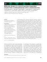
I-V characteristic of a PV panel simulated by MATLAB using Eq. (2.3) is shown below in
Figure: 2.5. For any given set of operational conditions, cells have a single operating point where
the values of the current (I) and Voltage (V) of the cell result in a maximum power output. The
power P is given by P=VI. A plot of panel output power vs. panel voltage is shown in figure: 2.5
which have a peak point indicated by MPP which falls off on both sides. This is known as
the maximum power point (MPP) and corresponds to the "knee" of the curve, at which the
module operates with the maximum efficiency and produces the maximum output power.
Current (A)
0.04
0.03
0.02
0.01
0
0
5
10
15
20
25
Voltage (V)
0.02
MPP
Power (W)
0.015
0.01
0.005
0
0
5
10
15
20
Voltage (V)
Figure: 2.5 I-V (top) and P-V (bottom) characteristic of a PV cell
14
25
2.5 I-V curve with load resistor
When a PV module is directly coupled to a load, the PV module’s operating point will be at the
intersection of its I–V curve and the load line which is the I-V relationship of load. For example
in Figure: 2.6, the load current,
……………………………….. (2.5)
Figure: 2.6 PV module is directly connected to a (variable) resistive load
For PV panel,
=
- [
] ................................. (2.6)
Plot of equation (2.5), shown as the load line, intersects the I-V characteristics of the P-V
module, plotted using (2.6), at different points determined by the load resistance R.
The intersection determines the operating voltage and current and the power delivered to the load
R. Figure: 2.7 shows load lines drawn for three different values of load resistance R. As it can be
seen,
15
12 Ohm Eff.=91%
1.2
16 Ohm
Eff.=100%
Current (A)
1
24 Ohm
Eff.=81%
0.8
0.6
0.4
Increasing R
0.2
0
0
5
10
15
20
25
Voltage (V)
Figure: 2.7 I-V curve for different resistive load
The load line with R=16Ω intersects the I-V characteristics at the MPP and therefore, draws the
maximum power. However, at any other value of R, the intersecting point shifts away from the
MPP and power absorbed will be less than the maximum power.
In other words, the impedance of load dictates the operating condition of the PV module. In
general, this operating point is seldom at the PV module’s MPP, thus it is not producing the
maximum power. This mismatching between a PV module and a load requires further oversizing of the PV array and thus increases the overall system cost.
DC-DC converter is widely used in DC power supplies and DC motor drives for the purpose of
converting unregulated DC input into a controlled DC output at a desired voltage level. MPPT
uses the same converter for a different purpose which is, regulating the input voltage at the PV
16
MPP and providing load matching for maximum power transfer. It can provide the output
voltage that is higher or lower than the input voltage.
IMPP
Io
+
+
DC-DC
Converter
Panel
VMPP
_
Ropt
vo
_
RLoad
RLoad
Figure: 2.8 PV with Load
When PV is directly coupled with a load, the operating point of PV is dictated by the load (or
impedance to be specific). The impedance of load is described as below,
……………………………. (2.7)
Where,
is the output voltage, and
is the output current.
The optimal load for PV is described as,
…………………………... (2.8)
Where,
and
When the value of
are the voltage and current at the MPP respectively.
matches with that of
, the maximum power transfer from PV to
the load will occur. These two are, however, independent and rarely matches in practice. The
goal of the DC-DC converter is to match the impedance of load to the optimal impedance of PV.
However, the MPP of a PV panel is not fixed but varies with different factors such as solar
irradiance and tempareture. In the following sections, we describe the variation of MPP with
different irradiance and temperature.
17
2.6 Effects of solar irradiance on MPP
There are two key parameters frequently used to characterize a PV cell. Shorting together the
terminals of the cell, the photon generated current will follow out of the cell as a short-circuit
current (Isc). When there is no connection to the PV cell (open-circuit), the photon generated
current is shunted internally by the intrinsic p-n junction diode. This gives the open circuit
voltage (Voc). The PV module or cell manufacturers usually provide the values of these
parameters in their datasheet.
In a PV cell current is generated by photons and output is constant under constant temperature
and constant incident radiation of light. Varying the irradiation we can get different output levels.
The current voltage relationship of a PV cell is given below,
………………………… (2.9)
To a very good approximation, the photon generated current, which is equal to
is directly
proportional to the irradiance (G), the intensity of illumination, to PV cell.
If Isc(Go) is the photo current at irradiance Go=1000W/m2 at the air mass AM = 1.5, then the
photon generated current at any other irradiance, G (W/m2), is given by,
………………………… (2.10)
So, the equation for varying irradiance,
………………. (2.11)
The MATLAB simulation of I-V characteristics according to equation (2.11) for different
irradiance of a PV panel is shown in Figure: 2.9. The value of Is as calculated using equation
(2.4) has been used.
18