Tài liệu The Design of Rolling Bearing Mountings P2 pdf
Bạn đang xem bản rút gọn của tài liệu. Xem và tải ngay bản đầy đủ của tài liệu tại đây (418.5 KB, 10 trang )
The Design of Rolling Bearing Mountings
PDF 3/8:
Machinery for working and processing non-metallic materials
Stationary gears
Motor vehicles
Rolling Bearings
FAG OEM und Handel AG Publ. No. WL 00 200/5 EA
The Design of
Rolling Bearing Mountings
Design Examples covering
Machines, Vehicles and Equipment
Publ. No. WL 00 200/5 EA
FAG OEM und Handel AG
A company of the FAG Kugelfischer Group
Postfach 1260 · D-97419 Schweinfurt
Telephone (0 97 21) 91-0 · Telefax (0 97 21) 91 34 35
Telex 67345-0 fag d
Preface
This publication presents design examples covering
various machines, vehicles and equipment having one
thing in common: rolling bearings.
For this reason the brief texts concentrate on the roll-
ing bearing aspects of the applications. The operation
of the machine allows conclusions to be drawn about
the operating conditions which dictate the bearing
type and design, the size and arrangement, fits, lubri-
cation and sealing.
Important rolling bearing engineering terms are print-
ed in italics. At the end of this publication they are
summarized and explained in a glossary of terms, some
supplemented by illustrations.
Contents
Example Title PDF
MACHINERY FOR WORKING AND
PROCESSING NON-METALLIC
MATERIALS
23 Vertical wood milling spindle . . . . . . . . . 3/8
24 Double-shaft circular saw . . . . . . . . . . . . 3/8
25 Rolls for a plastic calender . . . . . . . . . . . . 3/8
STATIONARY GEARS
26 Infinitely variable gear . . . . . . . . . . . . . . . 3/8
27 Spur gear transmission for a reversing
rolling stand . . . . . . . . . . . . . . . . . . . . . . . 3/8
28 Marine reduction gear . . . . . . . . . . . . . . . 3/8
29 Bevel gear – spur gear transmission . . . . . 3/8
30 Double-step spur gear . . . . . . . . . . . . . . . 3/8
31 Worm gear pair . . . . . . . . . . . . . . . . . . . . 3/8
MOTOR VEHICLES
Automotive gearboxes . . . . . . . . . . . . . . 3/8
32 Passenger car transmission . . . . . . . . . . . 3/8
33 Manual gearbox for trucks . . . . . . . . . . . 3/8
Automotive differentials . . . . . . . . . . . . . 3/8
34 Final drive of a passenger car . . . . . . . . . . 3/8
Automotive wheels . . . . . . . . . . . . . . . . . 3/8
35 Driven and steered front wheel of a
front drive passenger car . . . . . . . . . . . . . 3/8
36 Driven and non-steered rear wheel of a
rear drive passenger car . . . . . . . . . . . . . . 3/8
37 Driven and non-steered rear wheel of a
rear drive truck . . . . . . . . . . . . . . . . . . . . 3/8
38 Steering king pin of a truck . . . . . . . . . . . 3/8
39 Shock absorbing strut for the front
axle of a car . . . . . . . . . . . . . . . . . . . . . . . 3/8
Other automotive bearing arrangements
40 Water pump for passenger car and
truck engines . . . . . . . . . . . . . . . . . . . . . . 3/8
41 Belt tensioner for passenger car engines . 3/8
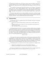
23 Vertical wood milling spindle
Operating data
Input power 4 kW; nominal speed 12,000 min
–1
.
Maximum load on the work end bearing:
radial – maximum cutting load of 0.9 kN,
axial – shaft weight and spring preload of 0.2 kN.
Maximum load on the drive end bearing:
radial – maximum belt pull of 0.4 kN,
axial – spring preload of 0.5 kN.
Bearing selection
Since a simple bearing arrangement is required the
bearing is not oil-lubricated as is normally the case for
such high-speed applications. Experience has shown
that grease lubrication is effective if deep groove ball
bearings of increased precision with textile laminated
phenolic resin cages are used. Where very high speeds
have to be accommodated, angular contact ball bear-
ings with a small contact angle (spindle bearings) are
often provided. These bearings are interchangeable
with deep groove ball bearings and can, therefore, be
employed without modifying the spindle design.
The work end features a deep groove ball bearing FAG
6210TB.P63 and the drive end a deep groove ball
bearing FAG 6208TB.P63. Two Belleville spring
washers preload the bearings to 500 N. Clearance-free
operation and high rigidity of the spindle system is,
therefore, ensured. In addition to this, the spring pre-
load ensures that both bearings are loaded under all
operating conditions, thus avoiding ball skidding
which may occur in unloaded bearings at high speeds,
which in turn may cause roughening of the surfaces
(increased running noise).
Bearing dimensioning
The size of the bearings is dictated by the shaft diame-
ter, which in turn is based on the anticipated vibra-
tions. The bearing sizes thus determined allow a suffi-
cient bearing life to be achieved so that a contamination
factor V = 0.5 0.3 can be assumed if great care was
taken to ensure cleanliness during mounting and
maintenance (relubrication). With this very good to
utmost cleanliness the bearings even can be failsafe.
Lubrication, sealing
Grease lubrication with FAG rolling bearing grease
Arcanol L74V. The bearings are packed with grease and
replenished at the required intervals. In view of the
high speeds the grease quantities should not, however,
be too large (careful regulation) so that a temperature
rise due to working of the grease is avoided.
As a rule, the bearings have to be relubricated every six
months, and for high speeds even more often.
Non-rubbing labyrinth seals are used instead of rub-
bing-type seals in order to avoid generation of addi-
tional heat.
Machining tolerances
Seat Diameter Cylindricity Axial runout
tolerance tolerance tolerance of the
(DIN ISO 1101) abutment shoulder
Shaft js5 IT2/2 IT2
Housing JS6 IT3/2 IT3
(work end)
Housing H6 IT3/2 IT3
(drive end)
23: Vertical milling cutter spindle
Work end
Drive end
24 Double-shaft circular saw
Operating data
Input power max. 200 kW;
max. speed 2,940 min
–1
.
Bearing selection
A simple bearing arrangement is required with stan-
dardized bearings which are suitable for very high
speeds and allow accurate shaft guidance. The required
high shaft rigidity determines the bearing bore diame-
ter.
The locating bearing is at the work end in order to keep
heat expansion in the axial direction as small as pos-
sible at this end. The two spindle bearings FAG
B7030E.T.P4S.UL are mounted in O arrangement.
The bearings of the UL universal design are lightly pre-
loaded by clamping the inner rings axially. The bearing
pair is suitable for high speeds.
The cylindrical roller bearing FAG NU1026M at the
drive end is the floating bearing. Heat expansion in the
axial direction is freely accommodated in the bearing.
The cylindrical roller bearing also accommodates the
high belt pull tension forces.
Machining tolerances
Shaft tolerance js5
Housing tolerance JS6
Lubrication, sealing
The bearings are greased for life, e.g. with FAG rolling
bearing grease Arcanol L74V.
Good sealing is required due to the dust arising during
sawing. Non-rubbing seals are used due to the high
speed. Flinger disks prevent the penetration of coarse
contaminants into the gap-type seals.
24: Double-shaft circular saw
25 Rolls for a plastic calender
Plastic foils are produced by means of calenders com-
prising several rolls made of chilled cast iron or steel
with polished surfaces which are stacked on top of
each other or arranged side by side.
Hot oil or steam flows through the rolls, heating the
O.D.s, depending on the material, to up to 220 °C
(rigid PVC), which ensures a good processibility of the
material. Rolls 1, 2 and 4 are subjected to deflection
under the high loads in the rolling gap. In order to still
achieve the thickness tolerances of the sheets in the mi-
crometer range, the deflection is compensated for by
inclining of rolls 1 and 3 and by counterbending of
rolls 2 and 4. Moreover, the narrow tolerance of the
foil thickness requires a high radial runout accuracy of
the bearings and adequate radial guidance of roll 3
which is only lightly loaded; this is achieved by pre-
loading the main bearing arrangement by means of
collaterally arranged, separate preloading bearings.
Operating data
Type: four-roll calender, F-shaped
Useful width 3,600 mm
Roll diameter 820 mm
Rolling gap 1st step 1.5 2 mm
2nd step 1 1.5 mm
3rd step 0.25 1 mm
Roll speed n = 6 24 min
–1
Inner ring temperature 170 °C
Roll mass 18 t (weight ≈ 180 kN)
Bearing system
To accommodate the radial and thrust loads, the four
rolls are supported at both ends by the same type of
main bearing arrangement. It consists of two double-
row cylindrical roller bearings forming the floating
bearing and of two double-row cylindrical roller bear-
ings plus one deep groove ball bearing forming the
locating bearing at the drive end. In addition, rolls 2
and 4 have to accommodate counterbending forces,
and roll 3 has to accommodate preloading forces.
These counterbending and preloading forces are sup-
ported at both roll ends in spherical roller bearings.
Bearing selection
Main bearing arrangement
The radial pressure by load of 1,620 kN resulting from
the maximum gap load of 4.5 kN/cm, as well as the
counterbending and preloading forces, are accommo-
dated by the main bearing arrangement at each end of
rolls 1, 2 and 4. The radial loads and the axial guiding
loads are accommodated by double-row FAG cylindri-
cal roller bearings (dimensions 500 x 650 x 130 mm)
and deep groove ball bearings FAG 61996M.P65.
At the locating bearing end the radially relieved deep
groove ball bearing accommodates only axial guiding
loads.
At the floating bearing end, heat expansions are com-
pensated by cylindrical roller bearings. Misalignments
resulting from shaft deflections and roll inclination are
compensated for by providing a spherical recess for the
bearing housings in the machine frame. The bearings
must be dimensionally stable up to 200 °C as their
inner rings may heat up to 180 °C as a result of roll
heating.
The high radial runout accuracy (≤ 5 µm) is achieved
by grinding the bearing inner rings and the roll body
to finished size in one setting at a roll surface tempera-
ture of 220 °C.The inner rings and the roll body can
be ground together due to the fact that the inner rings
of the cylindrical roller bearings – in contrast to those
of spherical or tapered roller bearings – can be easily
removed and mounted separately.
The dimension of the inner ring raceway after grind-
ing has been selected such that no detrimental radial
preload is generated even during the heating process
when the temperature difference between outer and
inner ring is about 80 K.
Roll arrangement 1 to 4
1 2
3
4
Rollbending bearings
A counterbending force is generated by means of
hydraulic jacks. The counterbending force (max.
345 kN per bearing location) is transmitted to the roll
neck by spherical roller bearings FAG
23980BK.MB.C5. The bearings ensure low-friction
roll rotation and accommodate misalignments result-
ing from shaft deflection.
Preloading bearings
The main bearings of roll 3 have to accommodate the
difference from the rolling forces from rolls 2 and 4. In
order to avoid uncontrolled radial roll movements, the
main bearings are preloaded with 100 kN via spherical
roller bearings FAG 23888K.MB.C5.
Bearing dimensioning
Two cylindrical roller bearings FAG 522028 mount-
ed side by side have a dynamic load rating of 2 x
2,160 kN. The load accommodated by the bearings is
calculated, depending on the load direction, from (roll
weight + press-on force + counterbending force)/2.
The dimensioning calculation is carried out for the
most heavily loaded roll 2 which rotates at an average
speed of 15 min
–1
.
The nominal life is approx. 77,000 hours. Due to the
high bearing temperature, the attainable life, which
takes into account the amount of load, lubricant film
thickness, lubricant additives, cleanliness in the lubri-
cating gap and bearing type, is only 42,000 hours.
The required bearing life of 40,000 h is reached.
Machining tolerances
Main bearings: Shaft to r6/housing to H6
Guiding bearing: Shaft to g6/housing radially
relieved
Preloading bearing: Shaft tapered/ housing H7
Rollbending bearing: Shaft tapered/ housing to H7
Lubrication
The bearings are lubricated with oil. The lubricant has
to meet very stringent requirements. Due to the low
speed and the high operating temperature, no elasto-
hydrodynamic lubricant film can form. As a result, the
bearings always operate in the mixed-friction range
and are exposed to the risk of increased wear. This con-
dition requires particularly suitable and tested lubricat-
ing oils.
A central circulation lubrication system with recooling
supplies all bearings with oil. Holes in the bearing
housings, circumferential grooves in the bearing outer
rings and in the spacers as well as radial grooves in the
outer faces feed the oil directly into the bearings.
Lip seals in the housing covers prevent dirt particles
from penetrating into the bearings.
dcba
25: Bearing arrangement of a plastic calender
a Main bearing arrangement (radial), at each end of all rolls:
2 cylindrical roller bearings
b Main bearing arrangement (axial), at the drive end of all rolls:
1 deep groove ball bearing 61996M.P65
c Preloading bearing arrangement, each end of roll 3:
1 spherical roller bearing 23888K.MB.C5
d Rollbending bearing arrangement, each end of rolls 2 and 4:
1 spherical roller bearing 23980BK.MB.C5
26 Infinitely variable gear
The main components of this infinitely variable gear
are two shafts linked by a chain which is guided by two
bevelled drive disks at each of the shafts. By varying
the distance between the bevelled drive disks the run-
ning circle of the chain increases or decreases, provid-
ing an infinitely variable transmission ratio.
Bearing selection
The two variator shafts are each supported by two
deep groove ball bearings FAG 6306.
The driving torque is transmitted by sleeve M via balls
to the bevelled disk hub H. The ball contact surfaces of
coupling K are wedge-shaped. Thus, sleeve and bev-
elled disk hub are separated depending on the torque
transmitted, and subsequently the contact pressure
between chain and disks is adapted to the torque.
Two angular contact thrust ball bearings FAG
751113M.P5 and one thrust ball bearing FAG
51110.P5 accommodate the axial loads resulting from
the contact pressure.
Torque variations are associated with small relative
movements between shaft and drive disks; for this rea-
son the two parts are separated by needle roller and
cage assemblies (dimensions 37 x 45 x 26 mm).
Lubrication
Oil bath lubrication provides for ample oil supply to
variator components and bearings.
Machining tolerances
Bearing Seat Diameter Cylindricity tolerance Axial runout tolerance
tolerance (DIN ISO 1101) of abutment shoulder
Deep groove ball bearing Shaft k5 IT3/2 IT3
Housing J6 IT3/2 IT3
Angular contact thrust ball bearings Bevelled disk hubs/ k5 IT2/2 IT2
and thrust ball bearing Sleeve IT3
Needle roller and Shaft h5 IT3/2 IT3
cage assembly Housing G6 IT3/2 IT3
26: Infinitely variable gear
27 Spur gear transmission for a reversing rolling stand
Operating data
The housing contains two three-step transmissions.
The drive shafts (1) are at the same level on the outside
and the output shafts (4) are stacked in the housing
centre.
Input speed 1,000 min
–1
; gear step-up 16.835:1;
input power 2 x 3,950 kW.
Bearing selection
Input shafts (1)
One cylindrical roller bearing FAG NU2336M.C3
and one four-point bearing FAG QJ336N2MPA.C3
form the locating bearing. The floating bearing is a cy-
lindrical roller bearing FAG NJ2336M.C3. The four-
point bearing is mounted with clearance in the hous-
ing (relieved) and, therefore, takes up just the axial
loads. The two cylindrical roller bearings only take up
the radial loads.
Intermediate shafts (2, 3)
The intermediate shafts have a floating bearing
arrangement with FAG spherical roller bearings:
22348MB.C3 and 24160B.C3 for shafts 2.
23280B.MB and 24164MB for shafts 3.
Output shafts (4)
A spherical roller bearing FAG 24096B.MB is used as
locating bearing. A full-complement single-row cylin-
drical roller bearing as a floating bearing compensates
for the thermal length variations of the shaft.
Machining tolerances
Input shafts (1):
Cylindrical roller bearing: – Shaft n6; housing J6
Four-point bearing: – Shaft n6; housing H7
Intermediate shafts (2 and 3):
Spherical roller bearing: – Shaft n6; housing
relief-turned.
Output shafts (4):
Cylindrical roller bearing: – Shaft p6; housing JS6
Spherical roller bearing: – Shaft n6; housing JS6
Lubrication
The bearings are also connected to the oil circulation
system for the transmission wheels. The oil (ISO
VG320) is fed directly to the bearing positions from
the oil filter.
27: Spur gear transmission for a reversing rolling stand