Electric machinery handbook fitzgerald mcgraw hill
Bạn đang xem bản rút gọn của tài liệu. Xem và tải ngay bản đầy đủ của tài liệu tại đây (8.17 MB, 126 trang )
Arthur E. Fitzgerald, Charles Kingsley, Jr., and Stephen D. Umans, Electric Machinery, Sixth
Edition, McGraw-Hill, 2003.
1.
2.
3.
4.
5.
6.
7.
8.
9.
10.
(Three-Phase Circuits)
(Magnetic Circuits and Magnetic Materials)
(Transformers)
(Electromechanical-Energy-Conversion Principles)
(Introduction to Rotating Machines)
(Synchronous Machines)
(Polyphase Induction Machines)
(DC Machines)
(Single- and Two-Phase Motors)
(Introduction to Marine and Aircraft Electrical Systems)
Bibliography
1. Yamayee and Bala, Electromechanical Energy Devices and Power Systems,
Wiley, 1994.
2. Ryff, Electric Machinery, 2/e, Prentice Hall, 1994.
3. Sen, Principles of Electric Machines and Power Electronics, 2/e, Wiley, 1997.
4. Cathey, Electric Machines, McGraw-Hill, 2001.
5. Sarma, Electric Machines, 2/e, West, 1994.
6. Wildi, Electrical Machines, Drives, and Power Systems, 5/e, Prentice Hall, 2002.
7. McGeorge, Marine Electrical Equipment and Practice, Newnes, 1993.
8. Pallett, Aircraft Electrical Systems, Wiley, 1987.
9.
1999
10.
1990
1
Chapter 1 Magnetic Circuits and Magnetic Materials
The objective of this course is to study the devices used in the interconversion of electric and
mechanical energy, with emphasis placed on electromagnetic rotating machinery.
The transformer, although not an electromechanical-energy-conversion device, is an important
component of the overall energy-conversion process.
Practically all transformers and electric machinery use ferro-magnetic material for shaping and
directing the magnetic fields that acts as the medium for transferring and converting energy.
Permanent-magnet materials are also widely used.
The ability to analyze and describe systems containing magnetic materials is essential for
designing and understanding electromechanical-energy-conversion devices.
The techniques of magnetic-circuit analysis, which represent algebraic approximations to exact
field-theory solutions, are widely used in the study of electromechanical-energy-conversion
devices.
§1.1 Introduction to Magnetic Circuits
Assume the frequencies and sizes involved are such that the displacement-current term in
Maxwell’s equations, which accounts for magnetic fields being produced in space by
time-varying electric fields and is associated with electromagnetic radiations, can be neglected.
H : magnetic field intensity, amperes/m, A/m, A-turn/m, A-t/m
B : magnetic flux density, webers/m2, Wb/m2, tesla (T)
1 Wb = 10 8 lines (maxwells); 1 T = 10 4 gauss
From (1.1), we see that the source of H is the current density J . The line integral of the
tangential component of the magnetic field intensity H around a closed contour C is equal
to the total current passing through any surface S linking that contour.
Hdl = J ⋅ da
(1.1)
c
s
Equation (1.2) states that the magnetic flux density B is conserved. No net flux enters or
leaves a closed surface. There exists no monopole charge sources of magnetic fields.
B ⋅ da = 0
(1.2)
s
A magnetic circuit consists of a structure composed for the most part of high-permeability
magnetic material. The presence of high-permeability material tends to cause magnetic flux
to be confined to the paths defined by the structure.
Figure 1.1
Simple magnetic circuit.
1
In Fig. 1.1, the source of the magnetic field in the core is the ampere-turn product N i , the
magnetomotive force (mmf) F acting on the magnetic circuit.
The magnetic flux φ (in weber, Wb) crossing a surface S is the surface integral of the
normal component B :
φ = B ⋅ da
s
φ c : flux in core, Bc : flux density in core
φ c = Bc Ac
H c : average magnitude H in the core.
(1.3)
(1.4)
The direction of H c can be found from the RHR.
F = Ni = Hdl
(1.5)
F = Ni = H c lc
(1.6)
The relationship between the magnetic field intensity H and the magnetic flux density B :
B = µH
(1.7)
Linear relationship?
µ = µ r µ 0 , µ : magnetic permeability, Wb/A-t-m = H/m
µ 0 = 4π × 10 −7 : the permeability of free space
µ r : relative permeability, typical values: 2000-80,000
A magnetic circuit with an air gap is shown in Fig. 1.2. Air gaps are present for moving
elements. The air gap length is sufficiently small. φ : the flux in the magnetic circuit.
Figure 1.2
Magnetic circuit with air gap.
Bc =
Bg =
φ
(1.8)
Ac
φ
(1.9)
Ag
F = H c lc + H g l g
F=
F =φ
Bc
lc +
Bg
(1.10)
g
(1.11)
lc
g
+
µAc µ 0 Ag
(1.12)
µ
2
µ0
Rc , R g : the reluctance of the core and the air gap, respectively,
Rc =
lc
g
, Rg =
µAc
µ 0 Ag
F = φ (Rc + R g )
φ=
φ=
F
Rc + R g
F
lc
g
+
µAc µ 0 Ag
(1.13), (1.14)
(1.15)
(1.16)
(1.17)
In general, for any magnetic circuit of total reluctance Rtot , the flux can be found as
F
(1.18)
φ=
Rtot
The permeance P is the inverse of the reluctance
1
(1.19)
Ptot =
Rtot
Fig. 1.3: Analogy between electric and magnetic circuits:
Figure 1.3
Analogy between electric and magnetic circuits: (a) electric ckt, (b) magnetic ckt.
Note that with high material permeability: Rc << R g and thus Rtot << R g ,
φ≈
Fµ 0 Ag
µ 0 Ag
F
=
= Ni
Rg
g
g
Fig. 1.4: Fringing effect, effective Ag increased.
Figure 1.4
Air-gap fringing fields.
3
(1.20)
In general, magnetic circuits can consist of multiple elements in series and parallel.
F = Hdl = Fk = H k l k
k
(1.21)
k
F = J ⋅ da
(1.22)
V =
(1.23)
s
Rk i k
k
in = 0
(1.24)
φn = 0
(1.25)
n
n
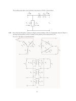
Figure 1.5
Simple synchronous machine.
4
§1.2 Flux Linkage, Inductance, and Energy
Faraday’s Law:
d
B ⋅ da
(1.26)
dt s
λ : the flux linkage of the winding, ϕ : the instantaneous value of a time-varying flux,
e : the induced voltage at the winding terminals
dϕ dλ
(1.27)
e=N
=
dt
dt
(1.28)
λ = Nϕ
L : the inductance (with material of constant permeability), H = Wb-t/A
c
E ⋅ ds = −
L=
λ
(1.29)
i
N2
L=
Rtot
The inductance of the winding in Fig. 1.2:
L=
Figure 1.6
N2
(g / µ
0
Ag )
(1.30)
=
N 2 µ 0 Ag
g
(a) Magnetic circuit and (b) equivalent circuit for Example 1.3.
5
(1.31)
6
Magnetic circuit with more than one windings, Fig. 1.8:
Figure 1.8
Magnetic circuit with two windings.
F = N 1i1 + N 2 i 2
φ = ( N 1i1 + N 2 i2 )
λ1 = N 1φ = N 12
µ 0 Ac
(1.32)
µ 0 Ac
(1.33)
g
µ 0 Ac
i1 + N 1 N 2
i2
g
g
λ1 = L11i1 + L12 i2
µ A
L11 = N 12 0 c
g
µ A
L12 = N 1 N 2 0 c = L21
g
µ A
µ A
λ2 = N 2φ = N1 N 2 0 c i1 + N 22 0 c i2
g
g
λ2 = L21i1 + L22 i2
µ A
L22 = N 22 0 c
g
Induced voltage, power (W = J/s), and stored energy:
d
e = (Li )
dt
d
e = L (Li )
dt
di
dL
e = L +i
dt
dt
dλ
p = ie = i
dt
∆W =
∆W =
λ2
λ1
t2
t1
i dλ =
W =
p dt =
λ2
λ
λ1
L
λ2
λ1
i dλ
dλ =
7
(1.35)
(1.36)
(1.37)
(1.38)
(1.39)
(1.40)
(1.41)
(1.42)
(1.43)
(1.44)
(1.45)
(
1 2
λ2 − λ12
2L
1 2 L 2
λ = i
2L
2
(1.34)
)
(1.46)
(1.47)
§1.3 Properties of Magnetic Materials
The importance of magnetic materials is twofold:
Magnetic materials are used to obtain large magnetic flux densities with relatively low
levels of magnetizing force.
Magnetic materials can be used to constrain and direct magnetic fields in well-defined
paths.
Ferromagnetic materials, typically composed of iron and alloys of iron with cobalt, tungsten,
nickel, aluminum, and other metals, are by far the most common magnetic materials.
They are found to be composed of a large number of domains.
When unmagnetized, the domain magnetic moments are randomly oriented.
When an external magnetizing force is applied, the domain magnetic moments tend to
align with the applied magnetic field until all the magnetic moments are aligned with the
applied field, and the material is said to be fully saturated.
When the applied field is reduced to zero, the magnetic dipole moments will no longer be
totally random in their orientation and will retain a net magnetization component along
the applied field direction.
The relationship between B and H for a ferromagnetic material is both nonlinear and
multivalued.
In general, the characteristics of the material cannot be described analytically but are
commonly presented in graphical form.
The most common used curve is the B − H curve.
Dc or normal magnetization curve:
Hysteresis loop (Note the remanance):
8
Figure 1.9 B-H loops for M-5 grain-oriented electrical steel 0.012 in thick.
Only the top halves of the loops are shown here. (Armco Inc.)
Figure 1.10 Dc magnetization curve for M-5 grain-oriented electrical steel 0.012 in thick. (Armco Inc.)
Figure 1.13
Hysteresis loop.
9
§1.4 AC Excitation
In ac power systems, the waveforms of voltage and flux closely approximate sinusoidal
functions of time.
We are to study the excitation characteristics and losses associated with
magnetic materials under steady-state ac operating conditions.
Assume a sinusoidal variation of the core flux ϕ (t ) :
ϕ (t ) = φ max sin ωt = Ac Bmax sin ωt
where
(1.48)
φ max = amplitude of core flux ϕ in webers
Bmax = amplitude of flux density Bc in teslas
ω = angular frequency = 2πf
f = frequency in Hz
The voltage induced in the N-turn winding is
e(t ) = ωNφ max cos(ωt ) = E max cos ωt
E max = ωNφ max = 2πfNAc Bmax
(1.49)
(1.50)
The Root-Mean-Squared (rms) value:
Frms =
E rms =
2π
2
1
T
T
o
f
2
(t )dt
(1.51)
fNAc Bmax = 2πfNAc Bmax
Note that the rums value of a sinusoidal wave is 1
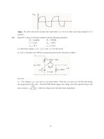
Excitation phenomena, Fig. 1.11:
ϕ vs iϕ ⇔ Bc vs H c , iϕ : exciting current.
Note that ϕ = Bc Ac and that iϕ = H c λ c / N .
10
2 times its peak value.
(1.52)
Figure 1.11
Excitation phenomena. (a) Voltage, flux, and exciting current;
(b) corresponding hysteresis loop.
I ϕ ,rms =
I c H c ,rms
(1.53)
N
I c H rms
N
= 2πfNBmax H rms ( Ac l c )
E rms I ϕ ,rms = 2πfNAc Bmax
Pa =
E rms I ϕ ,rms
mass
=
2πf
ρc
(1.54)
Bmax H rms
(1.55)
Pa : the exciting rms voltamperes per unit mass, mass = ρ c Ac λc
The rms exciting voltampere can be seen to be a property of the material alone.
depends only on Bmax because H rms is a unique function of Bmax .
It
Figure 1.12 Exciting rms voltamperes per kilogram at 60 Hz for
M-5 grain-oriented electrical steel 0.012 in thick. (Armco Inc.)
The exciting current supplies the mmf required to produce the core flux and the power input
associated with the energy in the magnetic field in the core.
Part of this energy is dissipated as losses and results in heating of the core.
The rest appears as reactive power associated with energy storage in the magnetic field.
This reactive power is not dissipated in the core; it is cyclically supplied and absorbed by
the excitation source.
11
Two loss mechanisms are associated with time-varying fluxes in magnetic materials.
The first is ohmic I 2 R heating, associated with induced currents in the core material.
Eddy currents circulate and oppose changes in flux density in the material.
To reduce the effects, magnetic structures are usually built of thin sheets of
laminations of the magnetic material.
2
Eddy-current loss ∝ f 2 , Bmax
The second loss mechanic is due to the hysteretic nature of magnetic material.
The energy input W to the core as the material undergoes a single cycle
H c lc
( Ac NdBc ) = Ac lc H c dBc
(1.56)
W = iϕ dλ =
N
For a given flux level, the corresponding hysteresis losses are proportional to the
area of the hysteresis loop and to the total volume of material.
Hysteresis power loss ∝ f
Information on core loss is typically presented in graphical form. It is plotted in terms of
watts per unit weight as a function of flux density; often a family of curves for different
frequencies are given. See Fig. 1.14.
Figure 1.13
Hysteresis loop; hysteresis loss is proportional to the loop area (shaded).
Figure 1.14 Core loss at 60 Hz in watts per kilogram for
M-5 grain-oriented electrical steel 0.012 in thick. (Armco Inc).
12
Figure 1.15
Laminated steel core with winding for Example 1.8.
13
§1.5 Permanent Magnets
Certain magnetic materials, commonly known as permanent-magnet materials, are
characterized by large values of remanent magnetization and coercivity. These materials
produce significant magnetic flux even in magnetic circuits with air gaps.
The second quadrant of a hysteresis loop (the magnetization curve) is usually employed for
analyzing a permanent-magnet material.
Br : residual flux density or remanent magnetization,
H c : coercivity, (1) a measure of the magnitude of the mmf required to demagnetize the
material, and (2) a measure of the capability of the material to produce flux in a magnetic
circuit which includes an air gap.
Large value (> 1 kA/m): hard magnetic material, o.w.: soft magnetic material
Fig. 1.16(a): Alnico 5, Br ≅ 1.22 T , H c ≅ −49 kA/m
Fig. 1.16(b): M-5 steel, Br ≅ 1.4 T , H c ≅ −6 kA/m
Both Alnico 5 and M-5 electrical steel would be useful in producing flux in unexcited
magnetic circuits since they both have large values of remanent magnetization.
The significant of remanent magnetization is that it can produce magnetic flux in a magnetic
circuit in the absence of external excitation (such as winding currents).
Figure 1.16
(a) Second quadrant of hysteresis loop for Alnico 5; (b) second quadrant of hysteresis loop for
M-5 electrical steel; (c) hysteresis loop for M-5 electrical steel expanded for small B. (Armco Inc.)
Figure 1.17
Magnetic circuit for Example 1.9.
14
Maximum Energy Product: a useful measure of the capability of permanent-magnet material.
The product of B and H has the dimension of energy density (J/m3)
Choosing a material with the largest available maximum energy product can result in the
smallest required magnet volume.
Consider Example 1.9. From (1.58) and (1.57), (1.59) can be obtained.
A
H mlm
B g = m Bm ,
= −1
(1.57) (1.58)
Ag
Hgg
B g2 = µ 0
= µ0
l m Am
(− H m Bm )
gAg
Vol mag
Vol air gap
Vol mag =
(1.59)
(− H m Bm )
Vol air gap B g2
µ 0 (− H m Bm )
(1.60)
Equation (1.60) indicates that to achieve a desired flux density in the air gap the required
volume of the magnet can be minimized by operating the magnet at the point of maximum
energy product.
A curve of constant B-H product is a hyperbola.
In Fig. 1.16a, the maximum energy product for Alnico 5 is 40 kJ/m3, occurring at the point
B = 1.0 T and H = −40 kA/m .
15
Figure 1.18
Magnetic circuit for Example 1.10.
§1.6 Application of Permanent Magnet Materials
Figure 1.19
Magnetization curves for common permanent-magnet materials.
16
Chapter 2 Transformers
This chapter is to discuss certain aspects of the theory of magnetically-coupled circuits, with
emphasis on transformer action.
The static transformer is not an energy conversion device, but an indispensable component in
many energy conversion systems.
It is a significant component in ac power systems:
Electric generation at the most economical generator voltage
Power transfer at the most economical transmission voltage
Power utilization at the most voltage for the particular utilization device
It is widely used in low-power, low-current electronic and control circuits:
Matching the impedances of a source and its load for maximum power transfer
Isolating one circuit from another
Isolating direct current while maintaining ac continuity between two circuits
The transformer is one of the simpler devices comprising two or more electric circuits coupled
by a common magnetic circuit.
Its analysis involves many of the principles essential to the study of electric machinery.
§2.1 Introduction to Transformers
Essentially, a transformer consists of two or more windings coupled by mutual magnetic flux.
One of these windings, the primary, is connected to an alternating-voltage.
An alternating flux will be produced whose magnitude will depend on the primary voltage,
the frequency of the applied voltage, and the number of turns.
The mutual flux will link the other winding, the secondary, and will induce a voltage in it
whose value will depend on the number of secondary turns as well as the magnitude of the
mutual flux and the frequency.
By properly proportioning the number of primary and secondary turns, almost any desired
voltage ratio, or ratio of transformation, can be obtained.
The essence of transformer action requires only the existence of time-varying mutual flux
linking two windings.
Iron-core transformer: coupling between the windings can be made much more effectively
using a core of iron or other ferromagnetic material.
The magnetic circuit usually consists of a stack of thin laminations.
Silicon steel has the desirable properties of low cost, low core loss, and high permeability
at high flux densities (1.0 to 1.5 T).
Silicon-steel laminations 0.014 in thick are generally used for transformers operating
at frequencies below a few hundred hertz.
Two common types of construction: core type and shell type (Fig. 2.1).
Figure 2.1 Schematic views of (a) core-type and (b) shell-type transformers.
1
Most of the flux is confined to the core and therefore links both windings.
Leakage flux links one winding without linking the other.
Leakage flux is a small fraction of the total flux.
Leakage flux is reduced by subdividing the windings into sections and by placing
them as close together as possible.
§2.2 No-Load Conditions
Figure 2.4 shows in schematic form a transformer with its secondary circuit open and an
alternating voltage v1 applied to its primary terminals.
Figure 2.4 Transformer with open secondary.
The primary and secondary windings are actually interleaved in practice.
A small steady-state current iϕ (the exciting current) flows in the primary and establishes
an alternating flux in the magnetic current.
e1 = emf induced in the primary (counter emf)
λ1 = flux linkage of the primary winding
ϕ = flux in the core linking both windings
N1 = number of turns in the primary winding
The induced emf (counter emf) leads the flux by 90 ο .
dλ
dϕ
e1 = 1 = N 1
(2.1)
dt
dt
v1 = R1iϕ + e1
(2.2)
e1 ≈ v1 if the no-load resistance drop is very small and the waveforms of voltage and flux
are very nearly sinusoidal.
ϕ = φ max sin ωt
(2.3)
dϕ
e1 = N1
= ωφ max cos ωt
(2.4)
dt
2π
E1 =
f N 1φ max = 2π f N 1φ max
(2.5)
2
V1
φ max =
(2.6)
2π f N 1
The core flux is determined by the applied voltage, its frequency, and the number of turns
2
in the winding. The core flux is fixed by the applied voltage, and the required exciting
current is determined by the magnetic properties of the core; the exciting current must
adjust itself so as to produce the mmf required to create the flux demanded by (2.6).
A curve of the exciting current as a function of time can be found graphically from the ac
hysteresis loop as shown in Fig. 1.11.
Figure 1.11 Excitation phenomena. (a) Voltage, flux, and exciting current;
(b) corresponding hysteresis loop.
If the exciting current is analyzed by Fourier-series methods, its is found to consist of a
fundamental component and a series of odd harmonics.
The fundamental component can, in turn, be resolved into two components, one in phase
with the counter emf and the other lagging the counter emf by 90 ο .
Core-loss component: the in-phase component supplies the power absorbed by
hysteresis and eddy-current losses in the core.
Magnetizing current: It comprises a fundamental component lagging the counter emf by
90 ο , together with all the harmonics, of which the principal is the third (typically 40%).
The peculiarities of the exciting-current waveform usually need not by taken into account,
because the exciting current itself is small, especially in large transformers. (typically
about 1 to 2 percent of full-load current)
Phasor diagram in Fig. 2.5.
Eˆ 1 = the rms value of the induced emf
ˆ = the rms value of the flux
Φ
Iˆ = the rms value of the equivalent sinusoidal exciting current
ϕ
Iˆϕ lags Eˆ1 by a phase angle θ c .
Figure 2.5 No-load phasor diagram.
3
The core loss Pc equals the product of the in-phase components of the Eˆ1 and Iˆϕ :
Pc = E1 I ϕ cos θ c
(2.7)
Iˆc = core-loss current, Iˆm = magnetizing current
§2.3 Effect of Secondary Current; Ideal Transformer
Figure 2.6 Ideal transformer and load.
Ideal Transformer (Fig. 2.6)
Assumptions:
1. Winding resistances are negligible.
2. Leakage flux is assumed negligible.
3. There are no losses in the core.
4. Only a negligible mmf is required to establish the flux in the core.
The impressed voltage, the counter emf, the induced emf, and the terminal voltage:
dϕ
dϕ
v1 = e1 = N 1
, v 2 = e2 = N 2
(2.8)(2.9)
dt
dt
v1 N1
=
(2.10)
v2 N 2
An ideal transformer transforms voltages in the direct ratio of the turns in its windings.
Let a load be connected to the secondary.
(2.11)(2.12)
N1i1 − N 2 i 2 = 0 , N1i1 = N 2 i 2
i1 N 2
=
(2.13)
i2 N1
An ideal transformer transforms currents in the inverse ratio of the turns in its
windings.
4
From (2.10) and (2.13),
v1i1 = v 2 i2
(2.14)
Instantaneous power input to the primary equals the instantaneous power output from
the secondary.
Impedance transformation properties: Fig. 2.7.
Errore.
Figure 2.7 Three circuits which are identical at terminals ab when the transformer is ideal.
N1
N
vˆ2 and vˆ2 = 2 vˆ1
N2
N1
N
N
Iˆ1 = 1 Iˆ2 and Iˆ2 = 2 Iˆ1
N2
N1
vˆ1 =
2
Vˆ1
N1
=
ˆI
N2
1
Z2 =
Vˆ2
Iˆ
(2.15)
(2.16)
(2.17)
2
Vˆ2
Iˆ
(2.18)
2
N1
Z1 =
N2
2
Z2
(2.19)
Transferring an impedance from one side to the other is called “referring the impedance
to the other side.” Impedances transform as the square of the turns ratio.
Summary for the ideal transformer:
Voltages are transformed in the direct ratio of turns.
Currents are transformed in the inverse ratio of turns.
Impedances are transformed in the direct ratio squared.
Power and voltamperes are unchanged.
5
§2.4 Transformer Reactances and Equivalent Circuits
A more complete model must take into account the effects of winding resistances, leakage
fluxes, and finite exciting current due to the finite and nonlinear permeability of the core.
Note that the capacitances of the windings will be neglected.
Method of the equivalent circuit technique is adopted for analysis.
Development of the transformer equivalent circuit
Leakage flux: Fig. 2.9.
Figure 2.9 Schematic view of mutual and leakage fluxes in a transformer.
L11 = primary leakage inductance, X 11 = primary leakage reactance
X 11 = 2π f L11
Effect of the primary winding resistance: R1
Effect of the exciting current:
N1 Iˆϕ = N 1 Iˆ1 − N 2 Iˆ2
(
)
= N 1 Iˆϕ + Iˆ2′ − N 2 Iˆ2
′ N
Iˆ2 = 2 Iˆ2
N1
Lm = magnetizing inductance, X m = magnetizing reactance
X m = 2π f Lm
6
(2.20)
(2.21)
(2.22)
(2.23)
Ideal transformer:
Eˆ 1 N 1
=
Eˆ 2 N 2
Secondary resistance, secondary leakage reactance
Equivalent-T circuit for a transformer:
N1
Xˆ 12 =
N2
2
N1
X 12 , R2′ =
N2
2
N1
R2 , V2′ =
N2
(2.24)
2
V2
(2.25)-(2.27)
Steps in the development of the transformer equivalent circuit: Fig. 2.10.
The actual transformer can be seen to be equivalent to an ideal transformer plus external
impedances
Refer to the assumptions for an ideal transformer to understand the definitions and
meanings of these resistances and reactances.
Errore.
Figure 2.10 Steps in the development of the transformer equivalent circuit.
7
Figure 2.11 Equivalent circuits for transformer of Example 2.3 referred to (a) the high-voltage side and (b) the low-voltage side.
§2.5 Engineering Aspects of Transformer Analysis
Approximate forms of the equivalent circuit:
Figure 2.12 Approximate transformer equivalent circuits.
8