(McGraw-Hill) (Instructors Manual) Electric Machinery Fundamentals 4th Edition Episode 1 Part 3 ppsx
Bạn đang xem bản rút gọn của tài liệu. Xem và tải ngay bản đầy đủ của tài liệu tại đây (616.59 KB, 20 trang )
35
8573 1.2 V
246.5 1.2 V
34.78
S
S
a
′
∠− °
== = ∠−°
V
V
The voltage regulation is
7967 8573
VR 100% 7.07%
8573
−
=×=−
2-7. A 5000-kVA 230/13.8-kV single-phase power transformer has a per-unit resistance of 1 percent and a per-
unit reactance of 5 percent (data taken from the transformer’s nameplate). The open-circuit test performed
on the low-voltage side of the transformer yielded the following data:
V
OC
kV= 138. A 1.15
OC
=I kW 9.44
OC
=P
(a) Find the equivalent circuit referred to the low-voltage side of this transformer.
(b) If the voltage on the secondary side is 13.8 kV and the power supplied is 4000 kW at 0.8 PF
lagging, find the voltage regulation of the transformer. Find its efficiency.
S
OLUTION
(a) The open-circuit test was performed on the low-voltage side of the transformer, so it can be used to
directly find the components of the excitation branch relative to the low-voltage side.
EX
15.1 A
0.0010942
13.8 kV
CM
YGjB=− = =
()()
11
OC
OC OC
44.9 kW
cos cos 77.56
13.8 kV 15.1 A
P
VI
θ
−−
== =°
EX
0.0010942 77.56 S 0.0002358 0.0010685 S
CM
YGjB j=− = ∠− °= −
1
4240
C
C
R
G
== Ω
1
936
M
M
X
B
==Ω
The base impedance of this transformer referred to the secondary side is
()
2
2
base
base
base
13.8 kV
38.09
5000 kVA
V
Z
S
== = Ω
so
(
)
(
)
EQ
0.01 38.09 0.38 R =Ω=Ω and
(
)
(
)
EQ
0.05 38.09 1.9 X =Ω=Ω. The resulting equivalent circuit
is shown below:
36
Ω= 38.0
sEQ,
R Ω= 9.1
sEQ,
jX
Ω= 4240
,sC
R
Ω= 936
,sM
X
(b) If the load on the secondary side of the transformer is 4000 kW at 0.8 PF lagging and the secondary
voltage is 13.8 kV, the secondary current is
()()
LOAD
4000 kW
362.3 A
PF 13.8 kV 0.8
S
S
P
I
V
== =
362.3 36.87 A
S
=∠−°I
The voltage on the primary side of the transformer (referred to the secondary side) is
EQPSS
Z
′
=+
VVI
()()
13,800 0 V 362.3 36.87 A 0.38 1.9 14,330 1.9 V
P
j
′
=∠°+∠−° +Ω=∠°V
There is a voltage drop of 14 V under these load conditions. Therefore the voltage regulation of the
transformer is
14,330 13,800
VR 100% 3.84%
13,800
−
=×=
The transformer copper losses and core losses are
()()
2
2
CU EQ,
362.3 A 0.38 49.9 kW
SS
PIR== Ω=
(
)
()
2
2
core
14,330 V
48.4 kW
4240
P
C
V
P
R
′
== =
Ω
Therefore the efficiency of this transformer at these conditions is
OUT
OUT CU core
4000 kW
100% 97.6%
4000 kW 49.9 kW 48.4 kW
P
PPP
η
=×= =
++ + +
2-8. A 200-MVA 15/200-kV single-phase power transformer has a per-unit resistance of 1.2 percent and a per-
unit reactance of 5 percent (data taken from the transformer’s nameplate). The magnetizing impedance is
j80 per unit.
(a) Find the equivalent circuit referred to the low-voltage side of this transformer.
(b) Calculate the voltage regulation of this transformer for a full-load current at power factor of 0.8
lagging.
(c) Assume that the primary voltage of this transformer is a constant 15 kV, and plot the secondary voltage
as a function of load current for currents from no-load to full-load. Repeat this process for power
factors of 0.8 lagging, 1.0, and 0.8 leading.
S
OLUTION
(a) The base impedance of this transformer referred to the primary (low-voltage) side is
()
2
2
base
base
base
15 kV
1.125
200 MVA
V
Z
S
== =Ω
so
(
)
(
)
EQ
0.012 1.125 0.0135 R =Ω=Ω
()( )
EQ
0.05 1.125 0.0563 X =Ω=Ω
37
()( )
100 1.125 112.5
M
X =Ω=Ω
The equivalent circuit is
EQ,
0.0135
P
R =Ω
EQ,
0.0563
P
Xj=Ω
not specified
C
R = 112.5
M
X =Ω
(b) If the load on the secondary side of the transformer is 200 MVA at 0.8 PF lagging, and the referred
secondary voltage is 15 kV, then the referred secondary current is
()()
LOAD
200 MVA
16,667 A
PF 15 kV 0.8
S
S
P
I
V
′
== =
16,667 36.87 A
S
′
=∠−°
I
The voltage on the primary side of the transformer is
EQ,PSSP
Z
′′
=+
VV I
()()
15,000 0 V 16,667 36.87 A 0.0135 0.0563 15, 755 2.24 V
P
j=∠°+ ∠−° + Ω=∠°V
Therefore the voltage regulation of the transformer is
15,755-15,000
VR 100% 5.03%
15,000
=×=
(c) This problem is repetitive in nature, and is ideally suited for MATLAB. A program to calculate the
secondary voltage of the transformer as a function of load is shown below:
% M-file: prob2_8.m
% M-file to calculate and plot the secondary voltage
% of a transformer as a function of load for power
% factors of 0.8 lagging, 1.0, and 0.8 leading.
% These calculations are done using an equivalent
% circuit referred to the primary side.
% Define values for this transformer
VP = 15000; % Primary voltage (V)
amps = 0:166.67:16667; % Current values (A)
Req = 0.0135; % Equivalent R (ohms)
Xeq = 0.0563; % Equivalent X (ohms)
% Calculate the current values for the three
% power factors. The first row of I contains
% the lagging currents, the second row contains
% the unity currents, and the third row contains
38
% the leading currents.
I(1,:) = amps .* ( 0.8 - j*0.6); % Lagging
I(2,:) = amps .* ( 1.0 ); % Unity
I(3,:) = amps .* ( 0.8 + j*0.6); % Leading
% Calculate VS referred to the primary side
% for each current and power factor.
aVS = VP - (Req.*I + j.*Xeq.*I);
% Refer the secondary voltages back to the
% secondary side using the turns ratio.
VS = aVS * (200/15);
% Plot the secondary voltage (in kV!) versus load
plot(amps,abs(VS(1,:)/1000),'b-','LineWidth',2.0);
hold on;
plot(amps,abs(VS(2,:)/1000),'k ','LineWidth',2.0);
plot(amps,abs(VS(3,:)/1000),'r ','LineWidth',2.0);
title ('\bfSecondary Voltage Versus Load');
xlabel ('\bfLoad (A)');
ylabel ('\bfSecondary Voltage (kV)');
legend('0.8 PF lagging','1.0 PF','0.8 PF leading');
grid on;
hold off;
The resulting plot of secondary voltage versus load is shown below:
2-9. A three-phase transformer bank is to handle 600 kVA and have a 34.5/13.8-kV voltage ratio. Find the
rating of each individual transformer in the bank (high voltage, low voltage, turns ratio, and apparent
power) if the transformer bank is connected to
(a) Y-Y, (b) Y-∆, (c) ∆-Y, (d) ∆-∆, (e) open-∆, (f) open-
Y—open-
∆
.
S
OLUTION
For the first four connections, the apparent power rating of each transformer is 1/3 of the total
apparent power rating of the three-phase transformer. For the open-∆ and open-Y—open-∆ connections,
the apparent power rating is a bit more complicated. The 600 kVA must be 86.6% of the total apparent
39
power rating of the two transformers, implying that the apparent power rating of each transformer must be
231 kVA.
The ratings for
each transformer in the bank for each connection are given below:
Connection Primary Voltage Secondary Voltage Apparent Power Turns Ratio
Y-Y 19.9 kV 7.97 kV 200 kVA 2.50:1
Y-
∆
19.9 kV 13.8 kV 200 kVA 1.44:1
∆
-Y
34.5 kV 7.97 kV 200 kVA 4.33:1
∆
-
∆
34.5 kV 13.8 kV 200 kVA 2.50:1
open-
∆
34.5 kV 13.8 kV 346 kVA 2.50:1
open-Y—open-
∆
19.9 kV 13.8 kV 346 kVA 1.44:1
Note: The open-Y—open-∆ answer assumes that the Y is on the high-voltage side; if the Y is on the low-
voltage side, the turns ratio would be 4.33:1, and the apparent power rating would be unchanged.
2-10. A 13,800/480 V three-phase Y-
∆
-connected transformer bank consists of three identical 100-kVA
7967/480-V transformers. It is supplied with power directly from a large constant-voltage bus. In the
short-circuit test, the recorded values on the high-voltage side for one of these transformers are
V
SC
V= 560
A 6.12
SC
=I
W 3300
SC
=P
(a) If this bank delivers a rated load at 0.85 PF lagging and rated voltage, what is the line-to-line voltage on
the primary of the transformer bank?
(b) What is the voltage regulation under these conditions?
(c) Assume that the primary voltage of this transformer bank is a constant 13.8 kV, and plot the secondary
voltage as a function of load current for currents from no-load to full-load. Repeat this process for
power factors of 0.85 lagging, 1.0, and 0.85 leading.
(d) Plot the voltage regulation of this transformer as a function of load current for currents from no-load to
full-load. Repeat this process for power factors of 0.85 lagging, 1.0, and 0.85 leading.
S
OLUTION
From the short-circuit information, it is possible to determine the per-phase impedance of the
transformer bank referred to the high-voltage side. The primary side of this transformer is Y-connected, so
the short-circuit phase voltage is
SC
,SC
560 V
323.3 V
33
V
V
φ
== =
the short-circuit phase current is
,SC SC
12.6 AII
φ
==
and the power per phase is
SC
,SC
1100 W
3
P
P
φ
==
Thus the per-phase impedance is
EQ EQ EQ
323.3 V
25.66
12.6 A
ZRjX=+ = = Ω
()()
11
SC
SC SC
1100 W
cos cos 74.3
323.3 V 12.6 A
P
VI
θ
−−
== =°
EQ EQ EQ
25.66 74.3 6.94 24.7 ZRjX j=+ = ∠°Ω= + Ω
40
EQ
6.94 R =Ω
EQ
24.7 Xj=Ω
(a) If this Y-
∆
transformer bank delivers rated kVA (300 kVA) at 0.85 power factor lagging while the
secondary voltage is at rated value, then each transformer delivers 100 kVA at a voltage of 480 V and 0.85
PF lagging. Referred to the
primary side of one of the transformers, the load on each transformer is
equivalent to 100 kVA at 7967 V and 0.85 PF lagging. The equivalent current flowing in the secondary of
one transformer referred to the primary side is
,
100 kVA
12.55 A
7967 V
S
I
φ
′
==
,
12.55 31.79 A
S
φ
′
=∠−°I
The voltage on the primary side of a single transformer is thus
PSSP
Z
EQ,,,,
′
+
′
=
φφφ
IVV
()()
,
7967 0 V 12.55 31.79 A 6.94 24.7 8207 1.52 V
P
j
φ
=∠°+ ∠− ° + Ω=∠°V
The line-to-line voltage on the primary of the transformer is
(
)
LL, ,
3 3 8207 V 14.22 kV
PP
VV
φ
== =
(b) The voltage regulation of the transformer is
8207-7967
VR 100% 3.01%
7967
=×=
Note: It is much easier to solve problems of this sort in the per-unit
system, as we shall see in the next problem.
(c) This sort of repetitive operation is best performed with MATLAB. A suitable MATLAB program is
shown below:
% M-file: prob2_10c.m
% M-file to calculate and plot the secondary voltage
% of a three-phase Y-delta transformer bank as a
% function of load for power factors of 0.85 lagging,
% 1.0, and 0.85 leading. These calculations are done
% using an equivalent circuit referred to the primary side.
% Define values for this transformer
VL = 13800; % Primary line voltage (V)
VPP = VL / sqrt(3); % Primary phase voltage (V)
amps = 0:0.0126:12.6; % Phase current values (A)
Req = 6.94; % Equivalent R (ohms)
Xeq = 24.7; % Equivalent X (ohms)
% Calculate the current values for the three
% power factors. The first row of I contains
% the lagging currents, the second row contains
% the unity currents, and the third row contains
% the leading currents.
41
re = 0.85;
im = sin(acos(re));
I(1,:) = amps .* ( re - j*im); % Lagging
I(2,:) = amps .* ( 1.0 ); % Unity
I(3,:) = amps .* ( re + j*im); % Leading
% Calculate secondary phase voltage referred
% to the primary side for each current and
% power factor.
aVSP = VPP - (Req.*I + j.*Xeq.*I);
% Refer the secondary phase voltages back to
% the secondary side using the turns ratio.
% Because this is a delta-connected secondary,
% this is also the line voltage.
VSP = aVSP * (480/7967);
% Plot the secondary voltage versus load
plot(amps,abs(VSP(1,:)),'b-','LineWidth',2.0);
hold on;
plot(amps,abs(VSP(2,:)),'k ','LineWidth',2.0);
plot(amps,abs(VSP(3,:)),'r ','LineWidth',2.0);
title ('\bfSecondary Voltage Versus Load');
xlabel ('\bfLoad (A)');
ylabel ('\bfSecondary Voltage (V)');
legend('0.85 PF lagging','1.0 PF','0.85 PF leading');
grid on;
hold off;
The resulting plot is shown below:
(d) This sort of repetitive operation is best performed with MATLAB. A suitable MATLAB program is
shown below:
% M-file: prob2_10d.m
42
% M-file to calculate and plot the voltage regulation
% of a three-phase Y-delta transformer bank as a
% function of load for power factors of 0.85 lagging,
% 1.0, and 0.85 leading. These calculations are done
% using an equivalent circuit referred to the primary side.
% Define values for this transformer
VL = 13800; % Primary line voltage (V)
VPP = VL / sqrt(3); % Primary phase voltage (V)
amps = 0:0.0126:12.6; % Phase current values (A)
Req = 6.94; % Equivalent R (ohms)
Xeq = 24.7; % Equivalent X (ohms)
% Calculate the current values for the three
% power factors. The first row of I contains
% the lagging currents, the second row contains
% the unity currents, and the third row contains
% the leading currents.
re = 0.85;
im = sin(acos(re));
I(1,:) = amps .* ( re - j*im); % Lagging
I(2,:) = amps .* ( 1.0 ); % Unity
I(3,:) = amps .* ( re + j*im); % Leading
% Calculate secondary phase voltage referred
% to the primary side for each current and
% power factor.
aVSP = VPP - (Req.*I + j.*Xeq.*I);
% Calculate the voltage regulation.
VR = (VPP - abs(aVSP)) ./ abs(aVSP) .* 100;
% Plot the voltage regulation versus load
plot(amps,VR(1,:),'b-','LineWidth',2.0);
hold on;
plot(amps,VR(2,:),'k ','LineWidth',2.0);
plot(amps,VR(3,:),'r ','LineWidth',2.0);
title ('\bfVoltage Regulation Versus Load');
xlabel ('\bfLoad (A)');
ylabel ('\bfVoltage Regulation (%)');
legend('0.85 PF lagging','1.0 PF','0.85 PF leading');
grid on;
hold off;
43
The resulting plot is shown below:
2-11. A 100,000-kVA 230/115-kV
∆
-
∆
three-phase power transformer has a per-unit resistance of 0.02 pu and a
per-unit reactance of 0.055 pu. The excitation branch elements are
pu 110=
C
R
and
pu 20=
M
X
.
(a) If this transformer supplies a load of 80 MVA at 0.85 PF lagging, draw the phasor diagram of one
phase of the transformer.
(b) What is the voltage regulation of the transformer bank under these conditions?
(c) Sketch the equivalent circuit referred to the low-voltage side of one phase of this transformer.
Calculate all of the transformer impedances referred to the low-voltage side.
S
OLUTION
(a) The transformer supplies a load of 80 MVA at 0.85 PF lagging. Therefore, the secondary line
current of the transformer is
()
80,000,000 VA
402 A
3 3 115,000 V
LS
LS
S
I
V
== =
The base value of the secondary line current is
()
base
,base
,base
100,000,000 VA
502 A
3 3 115,000 V
LS
LS
S
I
V
== =
so the per-unit secondary current is
()
1
,pu
,pu
402 A
cos 0.85 0.8 31.8
502 A
LS
LS
LS
I
I
−
== ∠ =∠−°I
44
The per-unit phasor diagram is shown below:
I
= 0.8
∠
-31.8°
V
= 1.0
∠
0°
S
V
P
θ
(b) The per-unit primary voltage of this transformer is
()( )
EQ
1.0 0 0.8 31.8 0.02 0.055 1.037 1.6
PS
Zj=+ =∠°+ ∠− ° + = ∠°VVI
and the voltage regulation is
1.037 1.0
VR 100% 3.7%
1.0
−
=×=
(c) The base impedance of the transformer referred to the low-voltage side is:
()
2
2
,base
base
base
3
3 115 kV
397
100 MVA
V
Z
S
φ
== =Ω
Each per-unit impedance is converted to actual ohms referred to the low-voltage side by multiplying it by
this base impedance. The resulting equivalent circuit is shown below:
(
)
(
)
EQ,
0.02 397 7.94
S
R =Ω=Ω
(
)
(
)
EQ,
0.055 397 21.8
S
X =Ω=Ω
(
)
(
)
110 397 43.7 k
C
R =Ω=Ω
(
)
(
)
20 397 7.94 k
M
X =Ω=Ω
Note how easy it was to solve this problem in per-unit, compared with Problem 2-10 above.
2-12. An autotransformer is used to connect a 13.2-kV distribution line to a 13.8-kV distribution line. It must be
capable of handling 2000 kVA. There are three phases, connected Y-Y with their neutrals solidly
grounded.
(a) What must the
SE
/
C
NN turns ratio be to accomplish this connection?
(b) How much apparent power must the windings of each autotransformer handle?
(c) If one of the autotransformers were reconnected as an ordinary transformer, what would its ratings be?
45
S
OLUTION
(a) The transformer is connected Y-Y, so the primary and secondary phase voltages are the line voltages
divided by
3
. The turns ratio of each autotransformer is given by
SE
13.8 kV/ 3
13.2 kV/ 3
HC
LC
VNN
VN
+
==
SE
13.2 13.2 13.8
CC
NN N+=
SE
13.2 0.6
C
NN=
Therefore,
SE
/
C
NN = 22.
(b) The power advantage of this autotransformer is
IO SE
22
23
CCC
WC C
SNNN N
SN N
++
== =
so 1/22 of the power in each transformer goes through the windings. Since 1/3 of the total power is
associated with each phase, the windings in each autotransformer must handle
()( )
2000 kVA
30.3 kVA
322
W
S ==
(c) The voltages across each phase of the autotransformer are
13.8/ 3
= 7967 V and
13.2/ 3
= 7621
V. The voltage across the common winding (
C
N
) is 7621 kV, and the voltage across the series winding
(
SE
N ) is 7967 kV – 7621 kV = 346 V. Therefore, a single phase of the autotransformer connected as an
ordinary transformer would be rated at 7621/346 V and 30.3 kVA.
2-13. Two phases of a 13.8-kV three-phase distribution line serve a remote rural road (the neutral is also
available). A farmer along the road has a 480 V feeder supplying 120 kW at 0.8 PF lagging of three-phase
loads, plus 50 kW at 0.9 PF lagging of single-phase loads. The single-phase loads are distributed evenly
among the three phases. Assuming that the open-Y—open-
∆
connection is used to supply power to his
farm, find the voltages and currents in each of the two transformers. Also find the real and reactive powers
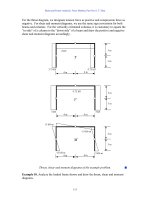
supplied by each transformer. Assume the transformers are ideal.
S
OLUTION
The farmer’s power system is illustrated below:
Load 1 Load 2
V
LL,P
V
LL,S
+
-
I
L,P
I
L,S
The loads on each phase are balanced, and the total load is found as:
1
120 kWP =
46
(
)
(
)
-1
11
tan 120 kW tan cos 0.8 90 kvarQP
θ
== =
2
50 kWP =
(
)
(
)
-1
22
tan 50 kW tan cos 0.9 24.2 kvarQP
θ
== =
TOT
170 kW P =
TOT
114.2 kvarQ =
11
TOT
TOT
114.2 kvar
PF cos tan cos tan 0.830 lagging
170 kW
Q
P
−−
== =
The line current on the secondary side of the transformer bank is
()()
TOT
170 kW
246.4 A
3 PF 3 480 V 0.830
LS
LS
P
I
V
== =
The open-Y—open ∆ connection is shown below. From the figure, it is obvious that the secondary voltage
across the transformer is 480 V, and the secondary current in each transformer is 246 A. The primary
voltages and currents are given by the transformer turns ratios to be 7967 V and 14.8 A, respectively. If
the voltage of phase A of the primary side is arbitrarily taken as an angle of 0°, then the voltage of phase B
will be at an angle of –120°, and the voltages of phases A and B on the secondary side will be
V 0480 °∠=
AS
V
and
V 120480 °−∠=
BS
V
respectively.
Note that line currents are shifted by 30
°
due to the difference between line and phase quantities, and by a
further 33.9
°
due to the power factor of the load.
-
-
-
+
+
+
-
V
A
= 7967∠0° V
V
B
= 7967 ∠-120° V
V
AS
= 480∠0° V
V
BS
= 480∠-120° V
.
.
I
AS
= 246∠-63.9° A
I
BS
= 246∠-183.9° A
I
CS
= 246∠56.1° A
I
φ
B
= 246∠-123.9° A
A
B
n
A
B
C
+
I
AP
= 14.8∠-63.9° A
I
BP
= 14.8∠-183.9° A
I
n
= 14.8∠56.1° A
The real and reactive powers supplied by each transformer are calculated below:
(
)
(
)
(
)
cos 480 V 246.4 A cos 0 63.9 52.0 kW
AASA
PVI
θ
==
(
)
(
)
(
)
sin 480 V 246.4 A sin 0 63.9 106.2 kvar
AASA
QVI
θ
==
(
)
(
)
(
)
cos 480 V 246.4 A cos 120 123.9 118 kW
BBSB
PVI
φ
θ
==
(
)
(
)
(
)
sin 480 V 246.4 A sin 120 123.9 8.04 kvar
BBSB
QVI
φ
θ
==
Notice that the real and reactive powers supplied by the two transformers are radically different, put the
apparent power supplied by each transformer is the same. Also, notice that the total power
AB
PP+
supplied by the transformers is equal to the power consumed by the loads (within roundoff error), while the
total reactive power
AB
QQ+ supplied by the transformers is equal to the reactive power consumed by the
loads.
47
2-14. A 13.2-kV single-phase generator supplies power to a load through a transmission line. The load’s
impedance is
load
500 36.87 Z =∠ °Ω, and the transmission line’s impedance is
line
60 53.1 Z =∠ °Ω.
(a) If the generator is directly connected to the load (Figure P2-3a), what is the ratio of the load
voltage to the generated voltage? What are the transmission losses of the system?
(b) If a 1:10 step-up transformer is placed at the output of the generator and a 10:1 transformer is
placed at the load end of the transmission line, what is the new ratio of the load voltage to the generated
voltage? What are the transmission losses of the system now? (Note: The transformers may be
assumed to be ideal.)
S
OLUTION
(a) In the case of the directly-connected load, the line current is
line load
13.2 0 kV
23.66 38.6 A
60 53.1 500 36.87
∠°
== = ∠−°
∠°Ω+∠ °Ω
II
The load voltage is
(
)
(
)
load load load
23.66 38.6 A 500 36.87 11.83 1.73 kVZ==∠−°∠°Ω=∠−°VI
The ratio of the load voltage to the generated voltage is 11.83/13.2 = 0.896. The resistance in the
transmission line is
(
)
line line
cos 60cos 53.1 36 RZ
θ
== °=Ω
so the transmission losses in the system are
(
)
(
)
2
2
loss line line
23.66 A 36 20.1 kWPIR== Ω=
(b) In this case, a 1:10 step-up transformer precedes the transmission line and a 10:1 step-down
transformer follows the transmission line. If the transformers are removed by referring the transmission
line to the voltage levels found on either end, then the impedance of the transmission line becomes
48
()
22
line line
11
60 53.1 0.60 53.1
10 10
ZZ
′
==∠°Ω=∠°Ω
The current in the referred transmission line and in the load becomes
line load
13.2 0 kV
26.37 36.89 A
0.60 53.1 500 36.87
∠°
′
== = ∠− °
∠°Ω+∠ °Ω
II
The load voltage is
(
)
(
)
load load load
26.37 36.89 A 500 36.87 13.185 0.02 kVZ==∠−°∠°Ω=∠−°VI
The ratio of the load voltage to the generated voltage is 13.185/13.2 = 0.9989. Also, the transmission
losses in the system are reduced. The current in the transmission line is
()
line load
11
26.37 A 2.637 A
10 10
II
== =
and the losses in the transmission line are
()()
2
2
loss line line
2.637 A 36 250 WPIR== Ω=
Transmission losses have decreased by a factor of more than 80.
2-15. A 5000-VA 480/120-V conventional transformer is to be used to supply power from a 600-V source to a
120-V load. Consider the transformer to be ideal, and assume that all insulation can handle 600 V.
(a) Sketch the transformer connection that will do the required job.
(b) Find the kilovoltampere rating of the transformer in the configuration.
(c) Find the maximum primary and secondary currents under these conditions.
S
OLUTION
(a) For this configuration, the common winding must be the smaller of the two windings, and
SE
4
C
NN= . The transformer connection is shown below:
+
-
+
-
120 V
600 V
N
C
N
SE
(b) The kVA rating of the autotransformer can be found from the equation
()
SE
IO
SE
4
5000 VA 6250 VA
4
CCC
W
C
NN NN
SS
NN
++
== =
(c) The maximum primary current for this configuration will be
6250 VA
10.4 A
600 V
P
P
S
I
V
== =
and the maximum secondary current is
49
6250 VA
52.1 A
120 V
S
S
S
I
V
== =
2-16. A 5000-VA 480/120-V conventional transformer is to be used to supply power from a 600-V source to a
480-V load. Consider the transformer to be ideal, and assume that all insulation can handle 600 V.
Answer the questions of Problem 2-15 for this transformer.
S
OLUTION
(a) For this configuration, the common winding must be the larger of the two windings, and
SE
4
C
NN= . The transformer connection is shown below:
+
-
+
-
480 V
600 V
N
C
N
SE
(b) The kVA rating of the autotransformer can be found from the equation
()
SE SE SE
IO
SE SE
4
5000 VA 25,000 VA
C
W
NN N N
SS
NN
++
== =
(c) The maximum primary current for this configuration will be
25,000 VA
41.67 A
600 V
P
P
S
I
V
== =
and the maximum secondary current is
25,000 VA
52.1 A
480 V
S
S
S
I
V
== =
Note that the apparent power handling capability of the autotransformer is much higher when there is only
a small difference between primary and secondary voltages. Autotransformers are normally only used
when there is a small difference between the two voltage levels.
2-17. Prove the following statement: If a transformer having a series impedance
eq
Z
is connected as an
autotransformer, its per-unit series impedance
eq
Z
′
as an autotransformer will be
SE
eq eq
SE C
N
Z
Z
NN
=
′
+
Note that this expression is the reciprocal of the autotransformer power advantage.
S
OLUTION
The impedance of a transformer can be found by shorting the secondary winding and
determining the ratio of the voltage to the current of its primary winding. For the transformer connected as
an ordinary transformer, the impedance referred to the primary (
C
N ) is:
50
+
-
+
-
N
C
N
SE
V
1
V
2
Z
1
Z
2
2
eq 1 2
C
SE
N
Z
ZZ
N
=+
The corresponding equivalent circuit is:
+
-
+
-
N
C
N
SE
V
1
V
2
Z
eq
When this transformer is connected as an autotransformer, the circuit is as shown below. If the output
windings of the autotransformer are shorted out, the voltages
H
V
will be zero, and the voltage
L
V
will be
+
-
+
-
N
C
N
SE
V
L
V
H
Z
eq
.
.
+
-
-
+
V
C
V
SE
I
SE
I
L
I
C
eq
Z
CL
IV =
where
eq
Z is the impedance of the ordinary transformer. However,
C
SE
CSE
C
SE
C
CSECL
N
NN
N
N
IIIIII
+
=+=+=
or
L
C
C
NN
N
II
+
=
SE
SE
so the input voltage can be expressed in terms of the input current as:
eqeq
Z
NN
N
Z
L
CSE
SE
CL
IIV
+
==
The input impedance of the autotransformer is defined as
LL
Z IV /
eq
=
, so
51
eqeq
Z
NN
N
Z
CSE
SE
L
L
+
==
′
I
V
This is the expression that we were trying to prove.
2-18. Three 25-kVA 24,000/277-V distribution transformers are connected in
∆
-Y. The open-circuit test was
performed on the low-voltage side of this transformer bank, and the following data were recorded:
line,OC
480 VV =
line,OC
4.10 AI =
3,OC
945 WP
φ
=
The short-circuit test was performed on the high-voltage side of this transformer bank, and the following
data were recorded:
line,SC
1600 VV =
line,SC
2.00 AI =
3,SC
1150 WP
φ
=
(a) Find the per-unit equivalent circuit of this transformer bank.
(b) Find the voltage regulation of this transformer bank at the rated load and 0.90 PF lagging.
(c) What is the transformer bank’s efficiency under these conditions?
S
OLUTION
(a) The equivalent of this three-phase transformer bank can be found just like the equivalent
circuit of a single-phase transformer if we work on a per-phase bases. The open-circuit test data on the
low-voltage side can be used to find the excitation branch impedances referred to the secondary side of the
transformer bank. Since the low-voltage side of the transformer is Y-connected, the per-phase open-circuit
quantities are:
,OC
277 VV
φ
=
,OC
4.10 AI
φ
=
,OC
315 WP
φ
=
The excitation admittance is given by
,
,
4.10 A
0.01480 S
277 V
OC
EX
OC
I
Y
V
φ
φ
== =
The admittance angle is
()( )
,
11
,,
315 W
cos cos 73.9
277 V 4.10 A
OC
OC OC
P
VI
φ
φφ
θ
−−
=− =− =− °
Therefore,
0.01483 73.9 0.00410 0.01422
EX C M
YGjB j=− = ∠− °= −
1/ 244
CC
RG==Ω
1/ 70.3
MM
XB==Ω
The base impedance for a single transformer referred to the low-voltage side is
()
()
2
2
,
base,
277 V
3.069
25 kVA
S
S
V
Z
S
φ
φ
== =Ω
so the excitation branch elements can be expressed in per-unit as
244
79.5 pu
3.069
C
R
Ω
==
Ω
70.3
22.9 pu
3.069
M
X
Ω
==
Ω
52
The short-circuit test data can be used to find the series impedances referred to the high-voltage side, since
the short-circuit test data was taken on the high-voltage side. Note that the high-voltage is
∆
-connected, so
,SC SC
1600 VVV
φ
==
,
,SC SC
/
3 1.1547 AII
φ
==
, and
,SC SC
/
3 383 WPP
φ
==
.
,
,
1600 V
1385
1.155 A
SC
EQ
SC
V
Z
I
φ
φ
== = Ω
()( )
,
11
,,
383 W
cos cos 78.0
1600 V 1.155 A
SC
SC SC
P
VI
φ
φφ
θ
−−
== =°
1385 78.0 288 1355
EQ EQ EQ
ZRjX j=+ = ∠°=+ Ω
The base impedance referred to the high-voltage side is
()
()
2
2
,
base,
24,000 V
23, 040
25 kVA
P
P
V
Z
S
φ
φ
== =Ω
The resulting per-unit impedances are
288
0.0125 pu
23,040
EQ
R
Ω
==
Ω
1355
0.0588 pu
23,040
EQ
X
Ω
==
Ω
The per-unit, per-phase equivalent circuit of the transformer bank is shown below:
+
-
V
S
V
P
I
S
+
-
I
P
R
C
jX
M
R
EQ
jX
EQ
0.0125 j0.0588
79.5 j22.9
(b) If this transformer is operating at rated load and 0.90 PF lagging, then current flow will be at an
angle of
()
9.0cos
1−
−
, or –25.8°. The per-unit voltage at the primary side of the transformer will be
(
)
(
)
EQ
1.0 0 1.0 25.8 0.0125 0.0588 1.038 2.62
PSS
Zj=+ =∠°+ ∠− ° + = ∠ °VVI
The voltage regulation of this transformer bank is
1.038 1.0
VR 100% 3.8%
1.0
−
=×=
(c) The output power of this transformer bank is
(
)
(
)
(
)
OUT
cos 1.0 1.0 0.9 0.9 pu
SS
PVI
θ
== =
The copper losses are
(
)
(
)
2
2
CU EQ
1.0 0.0125 0.0125 pu
S
PIR== =
53
The core losses are
()
2
2
core
1.038
0.0136 pu
79.5
P
C
V
P
R
== =
Therefore, the total input power to the transformer bank is
IN OUT CU core
0.9 0.0125 0.0136 0.926PP PP=++=+ + =
and the efficiency of the transformer bank is
OUT
IN
0.9
100% 100% 97.2%
0.926
P
P
η
=× = × =
2-19. A 20-kVA 20,000/480-V 60-Hz distribution transformer is tested with the following results:
Open-circuit test
(measured from secondary side)
Short-circuit test
(measured from primary side)
V
OC
= 480 V V
SC
= 1130 V
I
OC
= 1.60 A I
SC
= 1.00 A
V
OC
= 305 W P
SC
= 260 W
(a) Find the per-unit equivalent circuit for this transformer at 60 Hz.
(b) What would the rating of this transformer be if it were operated on a 50-Hz power system?
(c) Sketch the equivalent circuit of this transformer referred to the primary side if it is operating at 50 Hz.
S
OLUTION
(a) The base impedance of this transformer referred to the primary side is
(
)
()
2
2
base,
20,000 V
20 k
20 kVA
P
P
V
Z
S
== =Ω
The base impedance of this transformer referred to the secondary side is
()
()
2
2
base,
480 V
11.52
20 kVA
S
S
V
Z
S
== =Ω
The open circuit test yields the values for the excitation branch (referred to the secondary side):
,
,
1.60 A
0.00333 S
480 V
OC
EX
OC
I
Y
V
φ
φ
== =
()( )
11
305 W
cos cos 66.6
480 V 1.60 A
OC
OC OC
P
VI
θ
−−
=− =− =− °
0.00333 66.6 0.00132 0.00306
EX C M
YGjB j=− = ∠− °= −
1/ 757
CC
RG==Ω
1/ 327
MM
XB==Ω
The excitation branch elements can be expressed in per-unit as
757
65.7 pu
11.52
C
R
Ω
==
Ω
327
28.4 pu
11.52
M
X
Ω
==
Ω
The short circuit test yields the values for the series impedances (referred to the primary side):
54
1130 V
1130
1.00 A
SC
EQ
SC
V
Z
I
== = Ω
()()
11
260 W
cos cos 76.7
1130 V 1.00 A
SC
SC SC
P
VI
θ
−−
== =°
1130 76.7 260 1100
EQ EQ EQ
ZRjX j=+ = ∠°=+ Ω
The resulting per-unit impedances are
260
0.013 pu
20,000
EQ
R
Ω
==
Ω
1100
0.055 pu
20,000
EQ
X
Ω
==
Ω
The per-unit equivalent circuit is
+
-
V
S
V
P
I
S
+
-
I
P
R
C
jX
M
R
EQ
jX
EQ
0.013 j0.055
65.7 j28.4
(b) If this transformer were operated at 50 Hz, both the voltage and apparent power would have to be
derated by a factor of 50/60, so its ratings would be 16.67 kVA, 16,667/400 V, and 50 Hz.
(c) The transformer parameters referred to the primary side at 60 Hz are:
()()
base ,pu
20 k 65.7 1.31 M
CC
RZR==Ω=Ω
()()
base ,pu
20 k 28.4 568 k
MM
XZX==Ω=Ω
()()
EQ base E ,pu
20 k 0.013 260
Q
RZR==Ω=Ω
()()
EQ base E ,pu
20 k 0.055 1100
Q
XZX==Ω=Ω
At 50 Hz, the resistance will be unaffected but the reactances are reduced in direct proportion to the
decrease in frequency. At 50 Hz, the reactances are
()
50 Hz
568 k 473 k
60 Hz
M
X
=Ω=Ω
()
EQ
50 Hz
1100 917
60 Hz
X
=Ω=Ω