Giáo trình tính toán sàn nấm ( tiếng anh)
Bạn đang xem bản rút gọn của tài liệu. Xem và tải ngay bản đầy đủ của tài liệu tại đây (122.44 KB, 7 trang )
T
T
T
I
I
I
M
M
M
E
E
E
S
S
S
A
A
A
V
V
V
I
I
I
N
N
N
G
G
G
D
D
D
E
E
E
S
S
S
I
I
I
G
G
G
N
N
N
A
A
A
I
I
I
D
D
D
S
S
S
Two-Way Slabs
Portland Cement Association
Page 1 of 7
The following example illustrates the
design methods presented in the article
“Timesaving Design Aids for Reinforced
Concrete, Part 2: Two-way Slabs,” by
David A. Fanella, which appeared in the
October 2001 edition of
Structural
Engineer
magazine. Unless otherwise
noted, all referenced table, figure, and
equation numbers are from that article.
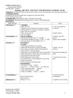
Example Building
Below is a partial plan of a typical floor in a
cast-in-place reinforced concrete building. In
this example, an interior strip of a flat
plate floor system is designed and detailed
for the effects of gravity loads according
to ACI 318-99.
20
′
-0
″
20
′
-0
″
20
′
-0
″
24′-0″
24′-0″
20
″
x 20
″
(typ.)
24
″
x 24
″
(typ.)
Design strip
T
T
T
I
I
I
M
M
M
E
E
E
S
S
S
A
A
A
V
V
V
I
I
I
N
N
N
G
G
G
D
D
D
E
E
E
S
S
S
I
I
I
G
G
G
N
N
N
A
A
A
I
I
I
D
D
D
S
S
S
Two-Way Slabs
Portland Cement Association
Page 2 of 7
Design Data
Materials
• Concrete: normal weight (150 pcf), ¾-
in. maximum aggregate, f′
c
= 4,000 psi
• Mild reinforcing steel: Grade 60 (f
y
=
60,000 psi)
Loads
• Superimposed dead loads = 30 psf
• Live load = 50 psf
Minimum Slab Thickness
Longest clear span l
n
= 24 – (20/12) =
22.33 ft
From Fig. 1, minimum thickness h per ACI
Table 9.5(c) = l
n
/30 = 8.9 in.
Use Fig. 2 to determine h based on shear
requirements at edge column assuming a
9 in. slab:
w
u
= 1.4(112.5 + 30) + 1.7(50) = 284.5 psf
A = 24 x [(20 + 1.67)/2] = 260 ft
2
A/c
1
2
= 260/1.67
2
= 93.6
From Fig. 2, d/c
1
≈ 0.39
d = 0.39 x 20 = 7.80 in.
h = 7.80 + 1.25 = 9.05 in.
Try preliminary h = 9.0 in.
Design for Flexure
Use Fig. 3 to determine if the Direct Design
Method of ACI Sect. 13.6 can be utilized to
compute the bending moments due to the
gravity loads:
• 3 continuous spans in one direction,
more than 3 in the other O.K.
• Rectangular panels with long-to-short
span ratio = 24/20 = 1.2 < 2 O.K.
• Successive span lengths in each
direction are equal O.K.
• No offset columns O.K.
• L/D = 50/(112.5 + 30) = 0.35 < 2 O.K.
• Slab system has no beams N.A.
Since all requirements are satisfied, the
Direct Design Method can be used.
T
T
T
I
I
I
M
M
M
E
E
E
S
S
S
A
A
A
V
V
V
I
I
I
N
N
N
G
G
G
D
D
D
E
E
E
S
S
S
I
I
I
G
G
G
N
N
N
A
A
A
I
I
I
D
D
D
S
S
S
Two-Way Slabs
Portland Cement Association
Page 3 of 7
Total panel moment M
o
in end span:
kips- ft2282
8
16718242850
8
w
M
2
2
n2u
o
.
..
=
××
==
ll
Total panel moment M
o
in interior span:
kips- ft0277
8
018242850
8
w
M
2
2
n2u
o
.
..
=
××
==
ll
For simplicity, use M
o
= 282.2 ft-kips for all
spans.
Division of the total panel moment M
o
into
negative and positive moments, and then
column and middle strip moments, involves
the direct application of the moment
coefficients in Table 1.
End Spans Int. Span
Slab
Moments
(ft-kips)
Ext. neg. Positive Int. neg. Positive
Total
Moment
73.4 146.7 197.5 98.8
Column
Strip
73.4 87.5 149.6 59.3
Middle
Strip
0 59.3 48.0 39.5
Note: All negative moments are at face of support.
T
T
T
I
I
I
M
M
M
E
E
E
S
S
S
A
A
A
V
V
V
I
I
I
N
N
N
G
G
G
D
D
D
E
E
E
S
S
S
I
I
I
G
G
G
N
N
N
A
A
A
I
I
I
D
D
D
S
S
S
Two-Way Slabs
Portland Cement Association
Page 4 of 7
Required slab reinforcement
.
Span Location
M
u
(ft-kips)
b*
(in.)
d**
(in.)
A
s
†
(in.
2
)
Min. A
s
‡
(in.
2
)
Reinforcement
+
End Span
Ext. neg. 73.4 120 7.75 2.37 1.94 12-No. 4
Positive 87.5 120 7.75 2.82 1.94 15-No. 4
Column
Strip
Int. Neg. 149.6 120 7.75 4.83 1.94 25-No. 4
Ext. neg. 0.0 168 7.75 --- 2.72 14-No. 4
Positive 59.3 168 7.75 1.91 2.72 14-No. 4
Middle
Strip
Int. Neg. 48.0 168 7.75 1.55 2.72 14-No. 4
Interior Span
Column
Strip
Positive 59.3 120 7.75 1.91 1.94 10-No. 4
Middle
Strip
Positive 39.5 168 7.75 1.27 2.72 14-No. 4
*Column strip width b = (20 x 12)/2 = 120 in.
*Middle strip width b = (24 x 12) – 120 = 168 in.
**Use average d = 9 – 1.25 = 7.75 in.
†A
s
= M
u
/4d where M
u
is in ft-kips and d is in inches
‡Min. A
s
= 0.0018bh = 0.0162b; Max. s = 2h = 18 in. or 18 in. (Sect. 13.3.2)
+
For maximum spacing: 120/18 = 6.7 spaces, say 8 bars
168/18 = 9.3 spaces, say 11 bars
Design for Shear
Check slab shear and flexural strength at
edge column due to direct shear and
unbalanced moment transfer.
Check slab reinforcement at exterior column
for moment transfer between slab and
column.
Portion of total unbalanced moment
transferred by flexure = γ
f
M
u
T
T
T
I
I
I
M
M
M
E
E
E
S
S
S
A
A
A
V
V
V
I
I
I
N
N
N
G
G
G
D
D
D
E
E
E
S
S
S
I
I
I
G
G
G
N
N
N
A
A
A
I
I
I
D
D
D
S
S
S
Two-Way Slabs
Portland Cement Association
Page 5 of 7
b
1
= 20 + (7.75/2) = 23.875 in.
b
2
= 20 + 7.75 = 27.75 in.
b
1
/b
2
= 0.86
From Fig. 5, γ
f
= 0.62*
γ
f
M
u
= 0.62 x 73.4 = 45.5 ft-kips
Required A
s
= 45.5/(4 x 7.75) = 1.47 in.
2
Number of No. 4 bars = 1.47/0.2 = 7.4,
say 8 bars
Must provide 8-No. 4 bars within an
effective slab width = 3h + c
2
= (3 x 9) +
20 = 47 in.
Provide the required 8-No. 4 bars by
concentrating 8 of the column strip bars
(12-No. 4) within the 47 in. slab width over
the column.
Check bar spacing:
For 8-No. 4 within 47 in. width: 47/8 =
5.9 in. < 18 in. O.K.
For 4-No. 4 within 120 – 47 = 73 in. width:
73/4 = 18.25 in. > 18 in.
Add 1 additional bar on each side of the
47 in. strip; the spacing becomes 73/6 =
12.2 in. < 18 in. O.K.
Reinforcement details at this location are
shown in the figure on the next page (see
Fig. 6).
∗
∗
The provisions of Sect. 13.5.3.3 may be utilized; however, they are not in this example.