DSpace at VNU: Compact Triple-Band MIMO Antenna with High Isolation for Handheld Application
Bạn đang xem bản rút gọn của tài liệu. Xem và tải ngay bản đầy đủ của tài liệu tại đây (779.69 KB, 10 trang )
VNU Journal of Science: Comp. Science & Com. Eng., Vol. 33, No. 1 (2017) 1-10
Compact Triple-Band MIMO Antenna with High Isolation
for Handheld Application
Duong Thi Thanh Tu1,2,*, Nguyen Gia Thang1,
Nguyen Thi Bich Phuong1, Vu Van Yem2
1
Posts and Telecommunications Institute of Technology, Hanoi, Vietnam
2
School of Electronics and Telecommunications,
Hanoi University of Science and Technology, Hanoi, Vietnam
Abstract
A multiband MIMO antenna design for broadband mobile's applications is proposed in this paper. Based on
PIFA structure, the proposed MIMO antenna is compact in size and designed on FR4 substrate with total
dimension of 37 x 43.6 x 6 mm3. At first, a single PIFA antenna is presented using U-shaped slots in radiating
patch which puts forward the antenna resonant in three frequencies: 2.4 GHz, 3.5 GHz and 6.3 GHz with
bandwidth of 8.9%, 18.3% and 3% respectively for Wi-Fi, Wimax/LTE and Direct Broadcast Satellite DBS of C
channel applications. Good reflection coefficient, antenna gain, and radiation pattern characteristics are obtained
in the frequency band of interest. Secondly, the paper has put forward another single type of tri-band PIFA
which uses double rectangular shape of Defected Ground Structure (DGS) technology. This helps increasing the
antenna efficiency at all frequencies as well as enhancing antenna gain of the PIFA. Finally, a MIMO PIFA
antenna is constructed by placing two single antennas side by side at close distance of 4 mm. The MIMO
antenna also gets high gain and radiation efficiency at all frequencies. To reduce the mutual coupling between
antenna elements, a combination of two “slot and variation” structures of DGS is proposed. Moreover, these
DGS structures have enhanced MIMO antenna bandwidth at all three bands, especially at 3.5 GHz resonant
frequency.
Received 12 April 2017, Revised 19 April 2017, Accepted 20 April 2017
Keywords: PIFA, Low mutual coupling, MIMO, DGS.
1. Introduction*
multiband for multi technologies. In last three
decades, Planar Inverted F Antenna (PIFA) has
emerged as one of the most promising
candidate for satisfying above demands. This is
due to advantages such as compact size, low
profile, light weight, and high radiation
efficiency [2]. However, one of the limitations
of PIFA antenna is narrow bandwidth which
makes this antenna type unsuitable for wideband commercial applications.
Besides, implementing multiple Input
Multiple Output (MIMO) technology is a key
Recently, wireless communication system
has advanced incredibly, especially in mobile
phone system. It is not only the dimensions of
end use equipment more and more decrease but
also number of internal antennas in one
terminal increase rapidly [1, 2]. These demand
internal antennas must be both compact to build
in practical mobile handsets and have
_______
*
Corresponding author. E-mail.:
/>
1
2
D.T.T. Tu et al. / VNU Journal of Science: Comp. Science & Com. Eng., Vol. 33, No. 1 (2017) 1-10
solution to increase the data rate in all future
generation of wireless communication systems
without needing additional frequency spectrum
or transition power [3]. Therefore, all the new
technologies for mobile communication require
MIMO antennas such as 802.11n, 802.11ac,
802.11ad, 802.16m, LTE, LTE-Advanced, and
5G. However, MIMO antenna systems require
high isolation between antenna elements,
especially for application in portable devices.
There are many decoupling methods have
been proposed for improving the isolation
between antenna elements in the MIMO system
but these solutions are not appropriate to apply
for MIMO PIFA antennas. In recent years,
several studies investigated for MIMO PIFA
antennas using combination of decoupling
solutions such as combination of slot,
neutralization line, and fork-shaped line [4],
using three slots of DGS (Defected Ground
Structure) and spacing solution (antenna
elements are place at the corners of mobile
equipment so the distance of antenna elements
are longer) [5], shorted strip and two slit in the
ground plane [6], and combination T-shaped
element and a neutral line [7]. However, most
of these studies have focused on the
applications for single band antenna design and
several ones for dual band MIMO. Few designs
of MIMO antenna with high isolation for triple
band or more are proposed but all of these using
spacing solution with long distance between
antenna elements or combination spacing
solution and other one [8-13].
In this paper, a triple band MIMO antenna
with high isolation is proposed. Two U shaped
slots into the main radiating patch of PIFA
antenna are inserted to achieve tri-band
operation at 2.4 GHz, 3.5 GHz and 6.3 GHz for
Wi-Fi, Wimax/LTE-Advanced and Direct
Broadcast
Satellite
DBS
of
C-band
applications. To improve antenna parameters of
single antenna such as radiating efficiency, gain
and bandwidth, two double rectangular shapes
defected ground structures (DGS) are used [14].
Moreover, other “slot and variation” shapes of
DGS have proposed to reduce the mutual
coupling between antenna elements (S12)
below -20 dB for all three resonant frequencies.
The distance of two patch antennas in the
MIMO systems is 4 mm, equivalent to 0.032
at 2.4 GHz resonant frequency. The antenna is
implemented on FR4 substrate of 1.6 mm
thickness with relative permittivity of 4.4 and
loss tangent of 0.02. The total dimension of
MIMO antenna is 37 x 43.6 x 6 mm3 that is
compact for portable devices.
2. Antenna design
2.1. Single Antenna
In this paper, the triple-band PIFA antenna
is designed for broadband wireless access
service at three different operating frequencies
which are 2.4 GHz for Wi-Fi application; 3.5
GHz for LTE - tablet or Wimax application and
6.3 GHz for up-link of C band satellite one. At
first, the total dimensions of the main radiating
patch need to be calculated according to the
desired resonant frequency. There are three
different operating frequencies for the tri-band
operation. Therefore, the lowest 2.4 GHz
resonant frequency is chosen first to calculate
approximately the total length, Lp and the
width, Wp of the patch by the equation (1).
(1)
where r is the relative permeability of the
medium between the ground and radiating
patch, h is the height of the patch in reference to
the ground.
(a) Top plane
D.T.T. Tu et al. / VNU Journal of Science: Comp. Science & Com. Eng., Vol. 33, No. 1 (2017) 1-10
3
2.2. MIMO Antenna
In this design, a MIMO model is
constructed by placing two DGS single antenna
side by side at the distance of 4 mm (0.032).
From
feeding point to feeding point, this
distance equivalent to 0.5 at 6.3 GHz resonant
frequency or 0.19 at 2.4 GHz. The layout of
the MIMO antenna is shown in Figure 2 with
total dimension of 37 x 43.6 x 6 mm3.
(b) Bottom plane
(c) Side plane
Figure 1. Structure of the proposed
triple-band PIFA antenna.
Then, two slots with U-shaped structure are
added to make the second and the third resonant
frequencies because this method not only
achieves multiband operation but also gets
enlarger bandwidth as well as minimizes guided
radiation towards the user end compared to
some other designs. To improve the
performance of PIFA antenna, two double
rectangular DGS structures are inserted in the
ground plane: The large one is used to improve
the antenna parameters at 2.4 GHz and 3.5 GHz
resonant frequencies and the small one is used
to improve the antenna parameters at 6.3 GHz.
All dimensions of DGS structures are optimized
by CST software. The geometric structure of
the proposed tri-band PIFA antenna and the
detail dimensions are shown in Figure 1 and
Table 1.
Table1. Detail dimensions of the proposed antenna
Parameter
Lg
Wg
Lu1
Wu1
Lu2
Wu2
g
Value
(mm)
37
19.8
9.2
18
6
8
1
Parameter
LDGS1
WDGS1
gDGS1
LDGS2
WDGS2
gDGS2
LDGS1
Value
(mm)
14.5
6.8
4
6
3.2
1.6
14.5
(a) Top plane
(b) Bottom plane-
(d) 3D
Figure 2. Structure of Proposed
triple-band MIMO antenna.
To reduce the mutual coupling between
MIMO elements for all three frequency bands, a
coordinated “slot and variation” shape of DGS
structure is used on ground plane. As shown in
Figure 3, a small DGS structure with 8-shape is
coordinated a long one with periodic loop shape
to increase isolation between antenna elements
at 2.4 GHz, 3.5 GHz and 6.3 GHz resonant
frequencies concurrently. The dimensions of the
DGS structures are optimized by CST software.
Detail dimensions of the proposed MIMO
antenna are shown on Table 2.
4
D.T.T. Tu et al. / VNU Journal of Science: Comp. Science & Com. Eng., Vol. 33, No. 1 (2017) 1-10
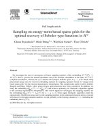
3. Simulation results
3.1. Single Antenna
The performance of the proposed single
antenna has simulated in CST software. The
reflection coefficient of antenna with and
without double rectangular DGS structures is
shown in Figure. 4.
Figure 4. The reflection coefficient of antenna with
and without double rectangular DGS structures.
(a)
(b)
Figure 3. The slot loaded structure (a) double square
shape (b) periodic rectangular shape.
Table 2. Detail dimensions of MIMO antenna
df
de
w1
w2
a1
a2
b1
Value
(mm)
23.8
4
20.1
20.6
2
1
3.4
b2
b3
Parameter
c1
c2
c3
c4
c5
d1
d2
Value
(mm)
21.05
0.5
8.85
0.9
0.5
2.4
0.5
0.5
d3
0.5
0.5
d4
0.45
Parameter
It is clearly seen that three resonant
frequencies are obtained. These are 2.4 GHz,
3.5 GHz and 6.3 GHz which covers Wi-Fi,
LTE/Wimax and C-band satellite band.
Reflection coefficients of the proposed antenna
are -26.44 dB, -42.87 dB, and -30.5 dB at
resonance frequencies of 2.4 GHz, 3.5 GHz,
and 6.3 GHz with the bandwidth of 201.8 MHz,
540 MHz, and 159.7 MHz respectively. By
applying DGS structure to ground plane,
several parameters of antenna are improved
such as 100 MHz bandwidth enlarger at 3.5
GHz as shown in Figure 4, radiation efficiency
and gain improvement as shown in Table 3.
Table 3. The comparison radiation efficiency and
gain of single antenna with and without DGS
Frequency (GHz)
With
Radiation
DGS
Efficiency
Without
(%)
DGS
With
DGS
Gain (dB)
Without
DGS
2.4
3.5
6.3
99.94
99.6
93.55
98.51
98.35
81
3.06
4.1
6.34
2.95
4.1
5.45
D.T.T. Tu et al. / VNU Journal of Science: Comp. Science & Com. Eng., Vol. 33, No. 1 (2017) 1-10
5
145.9 MHz at 2.4 GHz, 3.5 GHz and 6.3 GHz
respectively due to the mutual coupling.
(a) At 2.4 GHz
Figure 6. The S parameters of MIMO antenna with
distance from feed to feed is 0.5 at 6.3 GHz.
(b) At 3.5 GHz
(a) At 2.4 GHz
(c) At 6.3 GHz
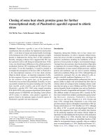
Figure 5. The 2D radiation pattern
of DGS single antenna.
2D radiation patterns for the three bands of
proposed antenna are illustrated in Figure 5 (a-c).
It is clear that the antenna get the smooth and high
directive 2D patterns. Besides, at all bands of
interest, the antenna gets high radiation efficiency
of over 93% as well as high gain.
(b) At 3.5 GHz
3.2. MIMO Antenna
The S parameters of MIMO system are
shown in Figure 6 with the distance of 4 mm. It is
clearly seen that the S12 of all bands are higher 20 dB because of close distance. In addition, the
bandwidths of antenna at all three bands are
decreased and get 202.6 MHz, 341.7 MHz and
(c) At 6.3 GHz
Figure 8. The 2D radiation pattern
of MIMO antenna.
6
D.T.T. Tu et al. / VNU Journal of Science: Comp. Science & Com. Eng., Vol. 33, No. 1 (2017) 1-10
The 2D radiation patterns also have
distorted their shape as shown in Figure 7.
However, the antenna still gets the smooth and
high directive 2D patterns. In addition, the
gains are better at 2.4 GHz and 3.5 GHz thanks
to structure of array antenna.
To reduce the mutual coupling between two
antenna element at this close distance, two “slot
and variation” DGS structures with 8-shape and
periodic loop shape are proposed. Recently,
DGS structure is one of techniques that widely
is used in MIMO antenna designs to improve
isolation between antenna elements because this
structure uses the dielectric as a band gap
structure to suppress mutual coupling as well as
to get a more compact size. However, almost
previous DGS studies have achieved a low
mutual coupling for flat antenna structure
whose height and substrate are the same. A few
researches focus on MIMO PIFA antennas but
only apply to single or dual band ones. As
illustrated in Figure 9, the proposed “slot and
variation” DGS structure with 8-shape and
periodic loop shape makes three stop-bands that
is able to suppress mutual coupling for tripleband MIMO antenna. This structure is also
useful for triple-band MIMO PIFA antenna.
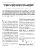
The Figure 10 shows the S parameters of the
MIMO antenna using the “slot and variation”
DGS structures for close distance of 4 mm
(0.032 at 2.4 GHz) from edge to edge. It is
clearly seen that the mutual coupling of MIMO
antenna using slot and variation DGS structures
is decreased, especially at 3.5 GHz. Besides, the
proposed MIMO antenna gets the high isolation
between antenna elements (S12 around -20 dB)
at all three bands.
Moreover, by applying DGS structure to the
ground, the performances of several MIMO
antenna parameters are improved. Firstly, the
bandwidths of MIMO antenna at all three bands
are increased. Especially at 3.5 GHz, the
bandwidth get 573.5 MHz which is enlarged
231 MHz. Then, the total efficiency and gain of
antenna are also improved lightly as shown in
Table 4 while the 2D radiation patterns at
interest bands are the same with smooth shape.
Figure 10. The S parameters of MIMO antenna with
and without slot and variation DGS structures at the
distance of 4 mm from edge to edge.
Table 4. The comparison radiation efficiency and
gain of MIMO antenna with and without “slot and
variation” DGS structure
Frequency (GHz)
2.4
3.5
6.3
With
DGS
92.9
93.3
90.4
Without
DGS
88.6
86.1
90.4
With
DGS
3.58
4.54
6.12
Without
DGS
3.5
4.24
5.84
Total
Efficiency
(%)
Gain (dB)
In MIMO antenna system, correlation
factor, which is so-called enveloped correlation
coefficient (ECC), will be significantly
degraded with higher coupling levels. The
factor can be calculated from radiation patterns
or scattering parameters. For a simple two-port
network,
assuming
uniform
multipath
Figure 9. The S12 parameters of decoupling
structure using “slot and variation” DGS.
environment, the enveloped correlation ( ),
D.T.T. Tu et al. / VNU Journal of Science: Comp. Science & Com. Eng., Vol. 33, No. 1 (2017) 1-10
can be calculated conveniently and quickly
from S-parameters as follows [17]:
(3)
The correlation factor curves of the
proposed MIMO antenna at three bands are
shown in Figure 11. From this figure, the tripleband PIFA MIMO antenna using “slot and
variation” DGS structure has the simulated
ECC lower than 0.01 for three interest bands.
Therefore, it is quite suitable for mobile
communication with a minimum acceptable
correlation coefficient of 0.5 [16] as well as for
LTE equipments with value of 0.3 for the
bands of interest [17].
Table 5 shows comparison between our
triple-band MIMO antenna using “slot and
variation” DGS structure to get low mutual
7
coupling and previous researches. It is obvious
that the proposed antenna gets S12 parameters
under -20 dB to meet the isolation demand of
good MIMO antenna [18] for all three bands
while distance from edge to edge is much closer
than all previous studies. Besides, the other
parameters such as -10 dB bandwidth and
efficiency are better.
Figure 11.Correlation Factor 12 curve for the
proposed MIMO antenna.
Table 5. The comparison between present design and previous researches
Resonant
Frequency
Ref
[10]
Ref
[11]
Ref
[12]
Ref
[13]
Ref
[14]
Our
design
L
2.45 GHz
5.25 GHz
5.775 GHz
2.45 GHz
3.5 GHz
5.2 GHz
5.75 GHz
1.77 GHz
7.86 GHz
2.02 GHz
8.89 GHz
780 MHz
1.8 GHz
3.2 GHz
900 MHz
1.8 GHz
2.6 GHz
3.5 GHz
2.4 GHz
3.5 GHz
6.3 GHz
Patch size
at low
frequency
Ground
size
15.6 x 10 x
4 mm3
50 x 100
mm2
11.5 x 13.8
x 4 mm3
50 x 100
mm2
10 x 31 x
4.5 mm3
8 x 27 x
4.5 mm3
40 x 100
mm2
9.75x17 x
6.4 mm3
50 x 100
mm2
25.7 x 17 x
0.8 mm3
80 x 100
mm2
19.6 x 19.8
x 6 mm3
37 x 43.6
mm2
-10 dB
Bandwidth
4%
3.84%
2.6%
5.1%
2.857%
2.4%
3.65%
0%
0%
8%
0%
0%
2.78%
9.3%
6.8 %
13 %
27 %
4.2 %
9.17 %
16.39 %
2.7 %
Mutual
coupling
at
resonant
frequency
-14 dB
-12 dB
-13 dB
-15 dB
-22 dB
-21 dB
-19.5 dB
-7 dB
-31 dB
-6.8 dB
-28 dB
-31dB
-11 dB
-11 dB
-15 dB
-16 dB
-18 dB
-40 dB
-20 dB
-20 dB
-22 dB
Distance
from
edge to
edge
18.8
mm
27 mm
22 mm
16 mm
144 mm
4 mm
Gain
3.34 dBi
x
x
4.5 dBi
4.12 dBi
6.07 dBi
5.9 dBi
0.5 dBi
3 dBi
0.9 dBi
1.75 dBi
1.8 dBi
1 dBi
3.5 dBi
3.2 dBi
1.5 dBi
3.58 dBi
4.54 dBi
6.12 dBi
Radiation
efficiency
x
x
x
93%
90%
86%
87%
48.9%
77.2 %
45.5 %
71.39%
x
x
x
x
x
x
x
92.9%
93.3%
90.4%
8
D.T.T. Tu et al. / VNU Journal of Science: Comp. Science & Com. Eng., Vol. 33, No. 1 (2017) 1-10
4. Measurement results
To verify the performance of the proposed
triple-band PIFA antenna, the antennas are
fabricated with single and MIMO model on
FR4 substrate with the thickness of 1.6 mm.
(a) Top view
(b) Bottom view
Figure 14. Fabricated triple-band
MIMO PIFA antenna.
(a) Top view
(b) Bottom view
Figure 12. Fabricated single triple-band PIFA.
Figure 15. Measured and simulated results of S
parameter of the proposed MIMO PIFA antenna.
Figure 13. Measured and simulated results of S11
parameter of the proposed single PIFA antenna.
Figure 12 shows a photography of single
antenna with total compact size of 37 x 19.8 x 6
mm3. The measured result of S11 parameter is
compared to simulation one in Figure 13. It is
clearly seen that the single antenna operates at
three bands of 2.4; 3.5 and 6.3 GHz with
10.5%, 27.5% and 4% bandwidth, respectively.
The proposed triple-band MIMO antenna
using “slot and variation” DGS structure is
fabricated on the FR4 substrate as shown in
Figure 14. The antenna gets compact in size of
37 x 43.6 x 6 mm3.
The measured results of S parameters are
compared to simulation ones in Figure 15. It is
clearly seen that the MIMO antennas operate at
2.4 GHz, 3.5 GHz and 5.7 GHz with over 10%,
20% and 5% bandwidth, respectively. The
mutual coupling at all interest bands are under 20 dB. It can be concluded that the measured
results agree well with the simulated ones.
Thus, using the proposed “slot and variation”
DGS structures can reduce the mutual coupling
between antenna elements in triple-band MIMO
antenna to ensure the isolation demand of good
MIMO antenna.
5. Conclusion
In this paper, a compact triple-band MIMO
PIFA antenna using U-shape slots as well as the
coordinate double rectangular with the “slot
D.T.T. Tu et al. / VNU Journal of Science: Comp. Science & Com. Eng., Vol. 33, No. 1 (2017) 1-10
and variation” DGS structures is proposed. The
total MIMO antenna occupies a small area of 37
x 43.6 mm2 on the FR4 substrate. The MIMO
antenna gets the large bandwidths which are
220 MHz, 573.5 MHz and 170 MHz at 2.4
GHz, 3.5 GHz and 6.3 GHz respectively. The
proposed MIMO PIFA antenna has solved the
narrow bandwidth limitation of conventional
PIFA. In addition, using novel DGS structures,
the antenna not only gets the extremely high
radiating efficiency of more than 90% for all
bands but also gets the high gain of the antenna
which is respectively 3.6 dB, 4.55 dB and 5.86
dB at 2.4 GHz, 3.5 GHz and 6.3 GHz operating
frequency, respectively. Besides, the MIMO
antenna has ensured the mutual coupling
between antenna elements under -20 dB for all
three bands with the narrow distance of 4 mm.
This proposed antenna is suitable for handheld
terminals of Wi-Fi, Wimax/LTE and C-band
satellite applications.
[5]
[6]
[7]
[8]
[9]
Acknowledgments
This work is partly supported by Motorola
Solutions
Foundation
under
Motorola
scholarship and research funding program for
ICT education.
[10]
References
[11]
[1] Hang Wong, Kwai-Man Luk, Chi Hou Chan,
Quan Xue, Kwok Kan So, Hau Wah Lai,
“Small
antennas
in
Wireless
Communications,” Proceedings of the IEEE
Journal, vol. 100, no 7, pp. 2109-2121, 2012.
[2] Rowell, C., Lam, E.Y., “Mobile phone
antenna design,” IEEE Antennas and
Propagation Magazine, vol. 54, no. 4, pp. 1434, 2012.
[3] Murch, R.D., and Letaief, K.B., “Antenna
systems for broadband wireless access,” IEEE
Communication Magazine, vol. 40, pp. 76–
83, 2002.
[4] Ahmed A. Naser, Khalil H. Sayidmarie, and
Jabir S. Aziz, “Compact High Isolation
Meandered-Line PIFA Antenna for LTE
[12]
[13]
9
(Band-Class-13)
Handset
Applications,”
Progress In Electromagnetics Research C, vol.
67, pp. 153–164, 2016.
Mustapha El Halaoui et al., “Dual Band PIFA
for WLAN and WiMAX MIMO Systems for
Mobile
Handsets,”
9 th
International
Conference Interdisciplinarity, Tirgu-Mures,
Romania, pp. 878-883, October 2015.
Do-Gu Kang, Jinpil Tak, and Jaehoon Choi,
“MIMO Antenna with High Isolation for
WBAN Applications,” International Journal
of Antennas and Propagation, Volume 2015,
Article ID 370763, 7 pages, 2015.
Ajinkya Vekhande, Ajinkya Joshi, Madhur
Kapse, Sagar Lohit, Yashashree Bhange,
“Dual Band Print Antenna for Wireless
Applications with Enhanced Isolation,” Int.
Journal of Engineering Research and
Applications, vol. 5, no. 4, pp. 82-84, 2015.
Majid Manteghi and Yahya Rahmat-Samii, “A
Novel Miniaturized Triband PIFA for MIMO
Applications,”
Micowave
and
Optical
Technology Letters, vol. 49, no. 3, pp. 724731, 2007.
Rashid Ahmad Bhatti, Jung-Hwan Choi, and
Seong-Ook
Park,
“Quad-Band
MIMO
Antenna Array for Portable Wireless
Communications Terminals,” IEEE Antenna
and Wireless propagation Letters, vol. 8, pp.
129-132, 2009.
K. Zhao , S. Zhang, and & S. L. He, “CloselyLocated MIMO Antennas of Tri-Band for
WLAN Mobile Terminal Applications,“
Journal of Electromagnetic Waves and
Applications, vol. 24, pp. 363–371, 2010.
J. Jasper Sweetlin, T. Anita Jones Mary,
“Mutual Decoupling in Quad Band MIMO
Slotted PIFA for Wireless Applications,” The
International Journal of Engineering and
Science (IJES), vol. 1, no. 2, pp. 303-307,
2012.
Jianfeng Zhu, Botao Feng, Li Deng, Biao
Peng, and Shufang Li, “Coupled-Fed Tri-Band
MIMO Antenna for WWAN and LTE
Application,”
Microwave
and
Optical
Technology Letters, vol. 59, no. 2, pp. 463468, February 2017.
Duong Thi Thanh Tu, Nguyen Gia Thang, Vu
Van Yem, “A Triple-band PIFA Antenna
Design Using Defected Ground Structure for
Handheld
Applications”.
International
Conference on Science and Technology,
pp.745-750, Nov 2016.
10
D.T.T. Tu et al. / VNU Journal of Science: Comp. Science & Com. Eng., Vol. 33, No. 1 (2017) 1-10
[14] J. Thaysen and K. B. Jakobsen, "Envelope
correlation in (N, N) MIMO antenna array from
scattering parameters," Microwave and Optical
Technology Letter, vol. 48, pp. 832-834, 2006.
[15] M. P. Karaboikis, V. C. Papamichael, G. F.
Tsachtsiris, and V. T. Makios, "Integrating
compact printed antennas onto small
diversity/MIMO
terminals,"
IEEE
Transactions on Antennas and Propagation,
vol. 56, pp. 2067-2078, 2008.
p
[16] 3GPP TS 36.101, V8.3.0. “EUTRA User
Equipment
Radio
Transmission
and
Reception,” September 2008.
[17] Istvan Szini, Alexandru Tatomirescu, and Gert
Frølund Pedersen, “On Small Terminal MIMO
Antennas, Harmonizing Characteristic Modes
with Ground Plane Geometry,” IEEE Antenna
Propag. Trans. On, vol. 63, no. 4, pp. 1487 1497, 2015.