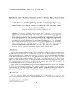
DSpace at VNU: Analysis and design of multimode interference coupler based racetrack resonators with the effects of higher order modes
Bạn đang xem bản rút gọn của tài liệu. Xem và tải ngay bản đầy đủ của tài liệu tại đây (524 KB, 6 trang )
VNU Journal of Science, Natural Sciences and Technology 23 (2007) 263-268
Analysis and design of multimode interference coupler based
racetrack resonators with the effects of higher order modes
Le Trung Thanh*
Uỉìiversity o f Transportations and Communications, Lang Thuong, Dong Da, Hanoi, Vietnam
Received 27 July 2007
Abstract. The design and analysis of a racetrack resonator based on a multimođe interĩerence
(MMI) coupler are presented in this paper. In order to describe the characteristics of an MMI
coupler, a matrix description of the MMI coupler, which takcs into account the eíĩect of higher
order modes in the structure, is developeđ. A design approach that is based on this matrix
description is proposed. The useíiilness of this design method is illustrated by means of an
example based on Silicon on Insulator (SOI) technology.
They can be coupleđ then to output fields and
1. Introducỉion
have
Racetrack resonators are promising devices
for
applications
in
communication. ư sing
the
íìeld
of
optical
this structure, basic
signal Processing íunctions such as vvavelength
an
effect
on
the
transtnission
characteristics. As a result, this simple model
can be applied only in ideal cases in which the
device is lossless and the matrix is unitary.
In [3], the design ideas of MMI coupler
íìltering, routing, switching, modulation, and
based
multiplexing can be achieved
[1,2]. Most
fabrication and designs have been proposed for
racetrack resonators have been designed and
the first time. It is different from the approach
íabricated using directional couplers or MMI
given in [4] for a double-ring resonator; in this
couplers as a coupling element between the ring
paper, we would like to develop the model
and the bus waveguides. The coupling element
proposed by [3] for a racetrack resonator in
is usually modelled by using a 2x2 universal
more detail, in which the analyses consider the
transmission matrix.
effect of higher order mode excitation within
the racetrack on the períòrmance o f the device.
Moreover, the geometry parameters o f the
waveguide are also optimized to achieve a
better performance. An overall design approach
is proposed which takes this effect into account.
However, due to the
presence o f bent waveguides in the racetrack
section, additional higher order modes can be
excited at the input o f the coupling region [3,4].
* Tel.: 84-4-7910197.
E-mail: thanhvii_au@ yahoo.com
racetrack
resonators
for
practical
264
L .T . T h a n h / V N U Ị o u m a l o f S cien c e, N a tu r a l S cie n c e s a n d T e c h n o lo g y 2 3 (2 0 0 7 ) 2 6 3 -2 6 8
2.2. M odelỉing o f the M M I coupler with the
effect o fh ig h er order modes
2. Theory
2.1. Conventional analysis
The general racetrack resonator based on an
MMI coupler is shown in Fig.l
ai
_______,
A
Fig. 1. Geometry of a racetrack resonator based
on a MMI coupler.
In order to take into account the excitation
of higher order modes in the coupling region,
an MMI model has been developed, in which a
3x3 transfer matrix is used [3]. By appropriate
design, the single mode condition for a straight
rib waveguide can be satisíĩed, but with the
presence o f bent waveguide sections in the
structure, the higher order modes can be
excited. In this paper it is assumed that there are
only two modes excited in the racetrack region
due to the curved vvaveguide sections. The
resulting model is shown in Fig. 2.
Here a^bị (i = 1,2) are complex amplitudes
at the input and output ports, R is the ring
radius, and LMW is the length o f the MMI
coupler and also is the length o f the straight
section. In the ideal case, the MMI coupler can
be described by a 2x2 transfer matrix and the
relations between the complex amplitudes at
input and output ports are expressed as [5]
T
X
K -K
'
k
•
•
7
)
a ^ a e ‘%
(2)
Fig. 2. Model describing the coupling between a
ring waveguide and sưaight waveguidc.
The relations betvveen the input and output
amplitudes are ứien givcn by
ịb t )
where
T,K
(|/c|2 + |r |2 = 1) are the ừansmission
and coupling coefficients o f the MMI coupler.
Light propagation through the resonator is
characterized by a round-trip transmission loss
a = e \p ( - a 0LR) , where a 0 (dB/cm) is the loss
coef!icient in the core o f the optical
waveguides. The round trip phase is given by
ệ = 2L ^ n n ^ ì Ằ , where LR = LMMI + 27ĩR is the
racetrack cừcumference as shown in Fig. 1.
ộ = ỊÌLK is the phase accumulated over the ring
waveguide with propagation
w here/? = 2n n ^ l Ả ,
constants
p ,
and X are effective
reữactive index o f the waveguide core and
optical wavelength, respectively.
ỉ>2
* il
K
\
f a 'ì
ứ2
T 22
^33
>
a2 = exp( - a 0LR) exp(jậ2)b2 = a l e x p ( # 2)ố2 (4)
a, = exp( - a ữLK) exp(y )6, = a 3expO
^ 3
where
and ốpốỊ
are
'^ 3
)b, (5)
the complex
amplitudes o f the fundamental mode at input
and output ports, rcspectively; a 3,ốj
are
amplitudes for the íìrst order modes; and
J( i , j = 1,2,3) are the coupling
and
ữansmission coefficients between these íields.
The round
trip phases are given
by
ệĩ = 2L Hn n tff IX for the fundamental mode
L .T . T h a n h / V N U Ị o u m a l o f S c ie n c e , N a tu r a l S c ie n c e s a n d T e c h n o lo g y 23 (2 0 0 7 ) 2 6 3 -2 6 8
with effective index ncjjữ and
265
the higher order modes in input vvaveguides has
a strongly effect on the períòrmance o f the
MMI coupler based devices.
Substituting (4) and (5) into (3), the
amplitude at the output port is given by
3. Sim ulation results and discussions
{ru +icna ĩxfeJ*‘ ) +
( 6)
and the normalised transmitted power at the
output port is
( r l i + K l ì a I x , e >*>) +
2
T = ầL
(7)
—
+aĩe* (*•„ +
1 -V iV
Here, the parameters X, and y t are given by
21
*I =
ì - a 2ĩ 22e *
___________
'
23
31 ; u<,2 32
1 - a 2Tĩ2e *
21
__________
l - a r 2a JAr32*,2jỄ;(***) - a 3rjjgM
depth 1.2ụ m , etched ratio factor r = 0.6 to
meet the single mode condition for the straight
waveguide; and bent waveguide radius
R = 400ụ m . Signal propagating via a bent
( 8)
waveguide vvill be lost and bending loss was
3dB at the radius R = 400ụ m , and the ừansition
(9)
loss between a bent waveguide and a straight
waveguide was calculated to be 0.1 dB.
(10)
It is assumed that the íield proíile in a
straight vvaveguide is a Gaussian proíile with a
mode width (ứữ. Figure 3 shows the field
and,
y = ________ g 2y 32r.2jgM-------------2 1- a ^ K ^ K ^ e ' ^ ***) -
In this section, we design and analyse the
device on SOI technology. The rib waveguides
were used in our simulations. The parameters
used in the simulations are as follows:
waveguides with rib widdi w = 2ụ m , etched
The ưansmission characteristic is calculated
from (7). It vvill be shown that the excitation of
proíìles o f a sừaight waveguide and a bent
waveguide with different radii as the parameter.
Fig. 3. Field profiles for a straight waveguide and a bent waveguide at diíĩerent radii.
266
L .T . T h a n h Ị V N U Ịo u r n a l o f S c ie n c e , N a tu r a l S c ie n c e s a n d T e c h n o lo g y 23 (2 0 0 7 ) 2 6 3 -2 6 8
It is clear that as the radius o f the bent
waveguide decreases, the higher order mode in
the bent waveguide can be excited and it will be
coupled to output ports as analysed above.
Figure 4 shows fields at the input
waveguide and within the MMI region when
the fundamental mode was excited. In this
paper, as an example, we consider a racetrack
resonator based on a 3dB MMI coupler. The
length o f the MMI coupler was determined by
the analytical analysis to be 226ụ m [6] and
numerical analysis to be 230ụ m
for a 3dB
coupling ratio as shown in Fig. 4.
Fig. 5. Fields at the input waveguide and A/ithin
MMI region with the excitation of the fưst ordcr
mode.
With the excitation of the higher order
mode within the coupling region, it is òetter to
model the MMI coupler using a 3x3 transícr
matrix as shown earlier in the paper. Thereíore,
the transmission and coupling coefficients need
to be calculated. By exciting the funcamental
mode at the input port ax, the transmission
coeíTicient
í
-
so,
ũl___ I____ I___Ị-------1---- ỉ--------------- u
0
2
*
«
8
0
Q
H ũ O L O h L é p csrtn r ( / M )
|r,i|2, along with the coupling
coefficients to the other
higher order mode in
calculated at different
coupler as shown in Fig.
output port ar.d to the
the raceừack, can be
lengths of the MMI
6.
Fig. 4. Fields at the input waveguide and within
MMI rcgion with the excitation of the íundamental
mode.
Due to the presence o f the bent waveguides,
the excitation o f higher order modes can occur
if the radius o f bent waveguides is too small;
thus a
parto f power within the higher order
modes will be coupled to the íundamental mode
and higher order modes at output waveguides.
As shown in Fig.5, the power o f the íirst order
mode excited in input vvaveguide is coupled to
the two output ports.
M M I le ngth ( j f n )
Fig. 6. Matrix coefílcients of the íundameLtal mode
at input port 1 coupled to output poits.
L .T . T h a n h / V N U Ị o u m a l o f S cien c e, N a tu r a l S c ie n c e s a n d T e c h n o lo g y 2 3 (2 0 0 7 ) 2 6 3 -2 6 8
Similarly, by exciting the íundamental
mode and higher order mode at the input bent
vvaveguide, the other transmission and coupling
coeíĩicients can be calculated as shown in Figs.
7 and 8.
267
First step: determine the vvaveguide
geometry to meet the single mode condition
following by SorePs well-known condition for
a straight waveguide [7).
Second step: optim ise the waveguide
parameters to obtain an acceptable level o f loss
for the desired racetrack radius.
Third step: Design the MMI couplers.
The transmission characteristic of the
device is then calculated and checked against
the desired períbrmance specifications.
And the last step is that fme tuning of the
dimensions and tolerance analysis can then be
carried out using a more accurate numerical
analysis
M M I le n g t h ( j j n )
Fig. 7. Matrix coeíTicients of the íundamental mode
at input port 2 coupled to output ports.
Đased on the above design steps,
transmission characteristics o f the device were
simulated. Figure 9 shows the transmission
characteristic for the ideal case, in which it is
assumed that higher order modes were not
excited in the bent waveguide sections and
losses vvere not considered; for the case in
which bending and transition loss are taken into
account; and fĩnally for the case in which higher
order mode excitation as wcll as losses were
considered.
M M I le n g th ( j j r t )
Fig. 8. Matrix coeíTicients of the higher order mode
at input port 2 coupled to ouíput ports.
It is obvious that the effects o f the higher
order modes vvithin the coupling region are not
neglected in the design and analysis o f the
device. From the designers point o f view, the
waveguide parameters should be chosen
optimally to obtain both single mode operation
and low losses. Thereíore, we would like to
propose five steps in the design as follows:
Fig. 9. Transmission characteristics of the device at
the MMI length 230///« (3dB coupler) for an ideal
case (dotted line), a case taking into account the
losses (solid line), and a case including both the
eíTect of higher order modes and the losses (dashed
line).
268
L .T . T h a n h / V N U Ị o u r n a l o f S cien c e, N a tu r a ỉ S c ie n c e s a n d T e c h n o lo g y 2 3 (2 0 0 7 ) 2 6 3 -2 6 8
It is obvious that the excitation o f the higher
order modes in the coupling region has strong
effects on the períbrmance o f the device.
Therefore, the bent waveguide radius and
waveguide geometry should be designed
careíully to mitigate against these effects.
4. Conclusion
In this paper, we have presented a method
for analysing and designing a racetrack
resonator based on the MMI coupler, in which
we have considered the eíĩects o f exciting the
higher
order
modes
on
the
device
characteristics. A novel design procedure which
takes into account the losses caused by bent
vvaveguides and the excitation o f the higher
order modes has been developed. This allows
one to design â racetrack resonator with desired
characteristics in practice.
Reíerences
[1] L. Cahill, The synthcsis o f gcncralised M achZehnder optical switches bascd on ĩTìultimode
intcrĩercncc (M M I) couplers, J. O ptical a n d
Q uantum Electronics 3 5 ,4 (2003) 465.
[2] L .w . C ahill, T.T. Le, MMI devices for photonic
signal Processing, Proc. IE E E 9th International
C onference on Transparent O pticaỉ Networks,
1-5 July, 2007, Rom c, Italy (invited papcr).
w.
[3] Thanh T rung Le, Laurcnce
Cahill, Analysis
and
Design
of
M M I-Based
Racetrack
R csonators, Proc.
The X V I Ịnternationaỉ
yVorkshop on O pticaỉ Waveguide Theorỵ an d
N um ericaỉ M odelling, Copcnhagcn, Denmark,
27-28 April, 2007
[4] L.C aruso, I. M ontrosset, A nalysis o f a racetrack
m icroring
rcsonator with MMI
coupler,
J. L ightw ave Technol. 21 (2003) 206.
[5] A. Y ariv, Universal relations for coupling o f
optical povver bctween m icro-resonators and
dielectric w avcguides, Electronics Letters 36
(2000) 321.
w. Cahill, Accuratc
[6] Thanh Trung Le, Laurence
M odeling
and
A nalysis
of
M ultim odc
Interícrcnce Structurcs by Fourier Techniquc,
The
Tenth
International sym posium
on
contem porary photonics technology (CPT2007')y
10-12 Jan., Tokyo, Japan, 2007.
[7] R.A. S orcí, J. Schm idtchcn, K.Petcưnan. Largc
singlc-m odc rib \vaveguides in GeSì-Si and Sio n - S i 0 2 , IEEE Quaní. Elec. 27 (1991), 1971.
Phân tích và thiết kế các bộ vi cổng hưởng dùng thiết bị giao
thoa đa mode MMI có xét đến ảnh hưởng của các mode bậc cao
Lê Trung Thành
Trường Đại học Giao thông Vận tải, Láng Thượng, Đống Đa, Hà Nội, Việt Nam
Bài báo đưa ra phương pháp phân tích và thiết kế các bộ vi cộng hưởng quang dùng thiết bị giao
thoa đa mode MMI (multimode interíerence). Bời sự có mặt của ổng dẫn sóng Ring ừong cấu trúc
thiết bị, nên không như các nghiên cứu trong trường hợp lý tưởng được đưa ra truớc đây, thiết bị MMI
trong phân tích cùa chúng tôi được đặc trưng bằng một ma trận 3x3 thay vi ma trận 2x2, trong đó ảnh
hường của các mode bậc cao được nghiên cứu. Để dễ dàng tích hợp với các thiết bị điện tử, sợi quang
hiện có, cũng như tận dụng được công nghệ chế tạo vi mạch hiện thời, và giảm kích thước cùa mạch,
thiết bị được thiết kế và mô phỏng trên công nghệ Silicon.