DSpace at VNU: Application of impedance technique for study of Ionic conducting properties of lixla1-x TiO3 Perovskite Thin films
Bạn đang xem bản rút gọn của tài liệu. Xem và tải ngay bản đầy đủ của tài liệu tại đây (3.28 MB, 8 trang )
VNU. JOURNAL OF SCIENCE, Mathematics - Physics, T.XXII, N01, 2006
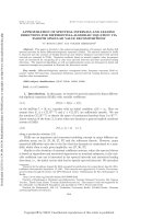
A P P L IC A T IO N O F IM P E D A N C E T E C H N IQ U E FO R ST U D Y O F
IO N IC C O N D U C T I N G P R O P E R T I E S O F L i.L a ^ T I O g P E R O V S K I T E
T H IN F IL M S
N g u y e n N a n g Dinh*, N g u y e n T h i B a o N g o c
D efartm ent o f E ngineering Physics & Ncinotechnogy, College o f Technology, V N U H
Le D i n h T r o n g
D efa rtm en t o f Physics, Pedagogical College, Hanoi II, X u a n Hoa, Virth Phuc
A b s t r a c t . Impedance spectroscopy (IS) technique has been analyzed and
applied to measure the ionic conductivity of the films. For a superionic
conductor, like a thin-film electrolyte, it is necessary to characterize IS by using
a two-electrodes ccll, where the thin film is deposited between two metallic
electrodes. In a very thin film, the Helmholtz layer strongly affects to the
conductivity during the measurement. So that, an equivalent scheme should be
chosen with a separation of three frequency zones to fit the theoretical curves to
experimental data. The best curve fitted with two to three circles is taken and
elaborated to determine all the parameters of the scheme, and R4 —a parameter
of the ionic conductivity - in particular.
Electron-beam-deposited LixL a lxTiO:, crystalline thin films were used for IS
measurements. Using the fitting method, the experimental data were fitted
with the circles obtained by the chosen equivalent scheme. From these circles,
the ionic conductivity at room temperature of a 350-nm thick Li012La088TiO3
film was found to be of Ơ = 6,52 xl 0 ° s.cm \
1. I n t r o d u c tio n
It is known t h a t for analyzing an ac cu rrent, Y-conductivity has been used,
w here Y = l/z . If z is z = I z I e'*, Y = 1 / 1z I e"*. T h u s Y is a vector with a value of
1/1z I a n d a n opposit p h a se to the phase of z. z is de p en d e n t on the frequence of the
ac c u rr e n t. T h e common a nd suitable ran ge used for study is of 10 mHz to 10 MHz.
In th e electrolytes, in solide sta te in p a rticu la r the ionic mobility is much smaller
t h a n the electron mobility, so t h a t to respond to the change of the electrical field, it
is neccessary to m e a s u r e in the ran ge of low frequencies. From the experimatal data
obtained in th e impe dance spectra (IS) one can d ete rm ine the ionic conductivity and
o t h e r p a r a m e t e r s such as the charge tran s p o rt, diffusion coefficient in solids.
However, it is so m etim es very difficult to analyze the res ults for thin films, because
for very th in films all above mentioned p a r a m e t e r s are strongly affected by the
*Corresponding author, email: \'H
54
A p p lic a tio n o f Im p e d a n c e T ech n iq u e fo r S tu d y o f
55
thickness and contacts in the m e a su r e m e n t cells. Thus, the choice of th e e qu iv a le n t
schemes consisting with subschemes of resistance, capacity, etc. plays a n i m p o r t a n t
role to find out real values of the pa ra m eters. One of the most i m p o r t a n t principles
to design th e eq uiv alent schemes is t h a t the total c u r r e n t value as well as th e phase
shift m u st have the sam e values as the measured sample do.
Recently, multicompound superionic conductors with a perovskite s t r u c tu r e
such as
LixLaỊ.xT i 0 3 have increasingly been studied. This is b ecause these
materials have a high Li-ion conductivity, even a t not very high t e m p e r a t u r e .
Especially, the thin-film formed LixL a l xT i 0 3 can be used in m an y scopes like allsold-state ionic batteries, electrochromic display, elctrochemical sensors, etc. [ 1].
However, in the experimental researches, to d e te rm in e the ionic conductivity
of the thin and/or very thin films of LixL a lxT i 0 3 by the IS techniq ue is alw ay s to
face many difficulties, t h a t obtained res ults often have a large error. So t h a t, the
aim of this work is to utilize this technique with an alysing a series of equ iv a le n t
schemes applied to fit with the obtained experimental d a ta from IS m e a s u r e m e n t s
on the thin films.
b.
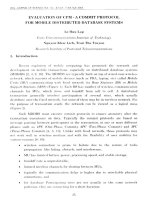
Fig. 1. Equivalent schemes of samples measured in an electrochemical cell (a)
and the corresponding elements of Zj part
2. A n a ly sis o f th e im p e d a n c e th eo ry
2.1. E q u iv a le n t sc h e m s fo r a three-electrodes cell a n d I S c h a r a c te r is tic s
It is well-known t h a t an equivalent scheme for the sa mple m e a s u r e d in th e
three-electrodes cell h a s a Randle scheme as presented in Fig. 1 . In th is schem e Cd
is the capacity of the double layer, Zf characterizes the electrochemical proccess. For
simplicity, z r is splitte d into two p a rt s connected in serial Rs a nd Cs or Rct a n d Zw,
where Rs a n d Cs, respectively is a real and an image p a rt of th e impedan ce, Rct is
Nguyen Nang Dinh, Nguyen Thi Ba o Ngoe, Le Dinh Trong
56
the resistance of the charge tran sp o rt , Zw is the W a r b u r g im p e d a n c e c h arac terizin g
a mass t r a n s p o r t , R 0 is th e resistance of the liquid electrolyte.
Among th ese p a r a m e t e r s , only Cd a nd R 0 are not d e p e n t onto th e frequency.
By calculation as shown in [2], the expression for the frequency r ela tio n ship of Rs
and C8, respectively is:
Cs = l/(ơ( 0 1/2)
Rs = Rct + G /o 1/2 a nd
(1)
where a is d e te r m i n e d as follows:
RT
Ơ=
(2 )
1/ 2 ^
Co
*
[>2 F 2 A n /2 V D
ưo
D 1R
*
J
Where R is th e ideal gas constant, T is th e absolute t e m p e r a t u r e , n is th e ion
valence, F - F a r a d a y constant, A - electrode area, DO, DR - diffusion coefficents,
r e s p e c t i v e ly
o f o x id a t io n
and
r e d u c tio n
r e a c t io n s , C q ,
C r - c o r r e s p o n d in g
ion
co n cen tra tio n s.
One can express the frequency dependences of th e real a n d image p a r t s of the
equivalent schem as follows:
K0 +
( c dơ( 0 112 + 1 )2 +C0 2 C Ỉ ( r , :i + ° “ ‘
c o C j 1(
z im
0
+ ơ w "1/2 1
r cI + ơo>- , / 2 )
1/2
(3)
Ơ + 1j
(4)
2
2
C d ơ c o l / 2 + l ) 1 ■K 0 2 C Ỉ ( R t , + c c o - 1' 2 )1
At th e low frequencies,
» 0, the equations (1) a n d (2) can be expressed as:
CD—
ZRe = Ro + Ret + ơ © ‘
1/2
(5)
z im = CTC0-"2 4- 2 ơ 2Cd
(6)
By combining two above equations, one can elim in a te
z im
= ZRe - R 0
-
Ret
CO
an d o b t a i n ’
+ 2 ơ 2Cd
T h a t is meaning, the image-vs-real part dependence is a linnear one, when
the image p a rt also approaches to zero, then the real p a rt h a s a value equals to:
(R0 +
(7)
CD->
0
Rct - 2ơ 2Cd).
In th e r a n g e of high AC frequency, the expressions (3) a n d (4), respectively
t ransfo rm into:
A p p l i c a t i o n o f I m p e d a n c e T e c h n iq u e f o r S t u d y of..
z :
=
57
c o C d R c.
im
| +
n
2 r
2 R
2
( )
c d R ct
From these e q u a t io n s one can combine in one expression of t h e other kind
r elationship be tw ee n th e real a n d image parts, as folows:
Í
n
Z
rc-
R 0 -
¥
2
\
/
n
R cl
(10)
)
This clearly d e m o n s t r a t e s t h a t in the graphic presentation, Zim- ZRe plot is a
half of a round. T his ro un d crosses the horizontal axis a t two points, th e first one is
a t R„ correspo nd ing to CO > 00 a n d the second one is at (R0 + Rct) - w h e n to -> 0. The
ionic conductivity (ơ) can be found from e x p erim en tal d a ta obtained for Rct, it is
d e te rm ine d as follows:
( 11)
SRa
where d a n d s , res pectiv ely is th e thickness and a re a of the working electrode.
2.2. E q u iv a le n t sch em fo r a two-electrodes cell a n d its im p ed a n ce sp ectru m
The theory of th e IS m ea su re d on a two-flat-electrodes cell has been developed
by MacDonall. Using this, the a uth ors of [3,4] have studied ionic conductance of solid
state electrolyte (or superionic matGrials). Basing on the MacDonall’s a r g u m e n t in
general, the im p ed an ce IS a n AC frequency function with threG characteristic ranges
of high, middle a n d low frequencies. Depending
on both the
composition and
structu re of the ionic m ateria ls, th e IS may have one, two or three circles in the Z| ZKp plots (Fig. 2 ). One can analyze the IS characteristics as follows:
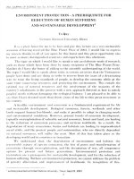
- High frequency range: In this range t h e r e is no charge t r a n s p o r t a t the
interface b o u n d a r i e s b e tw ee n t h e electrodes and electrolyte. The e q u iv a le n t scheme
IS p r e s e n t e d in Fig. 2a, w h e r e Cg is the geometrical capacity of t h e two parallel
electrodes in t h e solid electrolyte, Rb is the resistance of the electrolyte. T he IS h a s
one circle (Arc3).
- Middle frequency range: In this range, th e affect of th e geometrical capacity
can be neglected. T h e im p e d a n c e is determined m ainly by th e capicity of th e double
layer formed a t t h e c on ta cts be tw ee n the solid electrolyte a n d electrodes T h u s the
charge t r a n s p o r t a t th is in te rface is depen dent on th e reactions a t th e contacting
b oundaries. T h e e q u iv a le n t scheme is pre sented
in Fig. 2b, w h e r e R t is the
r esistance of th e c h a r g e t r a n s p o r t , Cdl is the capicity of the double layer (Helmholtz
layer). The c o rr e s p o n d i n g IS is Acr 2 circle.
- Low f req ue ncy range: in th e first half circle th e action of the
ions e n a b l e s to form a co n ce n tra tio n gradient of the ions with the
The im p e d a n c e plot h a s l i n e a r form with a slop e q u als to unit. When
c u r r e n t a cts like a quazy-DC one. T hus the ZIm -> 0 and ZRp
AC c u r r e n t on
im p ed an ce Zd.
co-» 0 the AC
t h e n h a s the
58
Nguyen Nang Dinh, Nguyen Thi B a o Ngoe , Le D inh Trong
corresponding value of Rct in the horizontal axis. The im pc d an c e sp e c tr u m h a s the
form of A r c l in Fig. 2.
Fig. 2. Equivalent schemes at different friquencies ranges and
corresponding impedance spectra of the samples measured by a twoelectrodes cell.
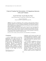
3. T he im p e d a n c e s p e c tr a o f LixLaj.xT i 0 3 th in film s
3 ,1 .
E x p e r i m e n t a l e v i d e n c e . The th in films of LixL a lxT i 0 3 with X “ 0.12 has
been prepared by electron beam deposition. The e x p er im e n tal im pedance spectra
obtained for two-electrodes cells vs. the film thickness a re show n in Fig. 3. For the
films thic ker 350 nm, the IS becomes na rrow er with th e decrease of the film
thickness. This is consistent with the MacDonall’s th eory for the two-electrodes
cells. From the th ic k nes s of 350 nm down, instead, the conductivity is increased, the
IS is not only condensed bu t also expanded into 2 tim es of th e circle r a d iu s (see d3
plot).
This
shows
that
the
MacDonall’s theory can be applied
onlv for the films with some critical
thickness. In p r e s e n t sa m ple s it is
aro und 350 nm. This may probably
^
be a tt r ib u t e d to the films thickness
o
effect. So that, the choice of
N
eq uiv ale nt schemes sim ilar to the
schemes from Fig. 1 is not suitable
more for such a t h in
film. It is
necessary to tak e th e
influence of
both the capacity of Helmholtz layer
a n d t h e c h a r g e of t h e c o n c e n t r a t i o n Fig. 3. Im pedance spectra o f L ixL a J^ r iU 3 tn in
g radien t
into
th e
eq uiv alent films with different thickness: d = 900 nm (dl),
^
650 nm (cL2) and 350 nm (d3)
A p p l i c a t i o n o f I m p e d a n c e T ec h n iq u e for S t u d y of..
59
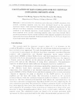
3.2.
A n a l y s i s a n d e s t im a ti o n o f ionic c o n d u c t i v i t y . Figure 4 p r e s e n ts the
IS data (dark points) of a 350 nm - thick LixL a l xT i 0 3 film. In the frequency range
from 10 mHz to 10 MHz, the
IS splits on two clear circles.
Moreover, th e second circle
s t a r t s at th e frequency when
the first circle is not finished
yet. This shows t h a t all th e
processes occuring in the
middle a nd low frequencies
have strongly affected to the
samples.
In deed,
the
a p p ea ra n c e of large circle
concernning
to
the
low
frequency ra n g e proves a
much
considerably
large
influence
of
the
electrochem ical processes in P ig 4 Im pedance spectra d a ta (dark p o in ts) o f a 350the interface b e tw ee n th e nm thick LiJLdj.xTiOfr measured in frequency range from
solid
electrolyte *
a n d 10 mHz to 10 MHz. The solid circles are the fitted IS
electrodes. T h u s, for fitting obtained from the equivalent scheme of Fig.
5
the theoretic al IS with the
ex p erim e ntal d a t a it is neccessary to design a series of e quiv ale nt schem es where
above mentioned processes m u s t be take n in considering. Using software available
in the A uto.L ab-Pote ntiostat-PGS-3 0, one can choose different parallel a n d serial
pa rts of th e sch em es to design an equ ivalent schem e t h a t is most fitted with
e xperim ental circles. By th is method we have obtained a scheme as p r e s e n t e d in
fig. 5. The r e s u l t of th is fitting is shown by the solid circles in Fig. 4 .
1 he e q u iv a le n t schem e in Fig. 5 consists of t h r e e p a r t s corresponding to three
ranges of AC freque ncies, as follows:
- The p a r t I h a s only R l , the resistance of contact a nd
depend on th e frequency. So th e impedance has only real part.
lead wires does
not
The p a r t II c h a r a c t e r i z e s the contribution of th e electrochemical processes in
the interface b e tw ee n t h e t h i n film and electrodes. Here R2 is th e res istan c e of
metal/solid electrolyte contact; C l and R3, respectively are the capacity and the
resistan ce cau sed by th e concentration of ions in th e electrolyte; C2 is the capacity
of the Helmholtz layer ( t h a t strongly affect to th e sa mple when th e l a s t is thin
enough). Besides, Q c h a r a c t e r i z e s the grain
a n d b ou n da rie s size effect. Its
corre sponding im p e d a n c e is Z(Q) = A*(jco)'n, where n = 0 , Q is intrinsic resistance, n
= 0.55, Q is th e W a r b u r g impedan ce, a nd n = 1 , Q is the capacity.
- The p a r t III c h a r a c t e r i z e s ionic conductivity of the t h in films in th e low
frequency range. H e re C3 is th e capacity formed betw een th e two parallel electrodes
and R4 is the r e s i s t a n c e of th e ionic conductance.
Nguyen N a n g Dinh , Nguyen Thi Bao Ngoe , Le Dinh Trong
60
T a b l e 1. P re se n ted all the values of the p a r a m e t e r s obtained from the
calculation by this eq uiv alent scheme.
F ig . 5. Equivalent schemes for a 350 nm - thick film o f LixL a l xT i0 3
Table 1. Physical parameters determined from the equivalent scheme in Fig. 5 for the
Lio 12^"^0
thin film
(I)
(III)
(II)
R1(Q)
R2(Q)
R3(Q)
Cl(nF)
C2(|iF)
794
-2,5
37
103
0,61
Q
A(Q)
n
0 , 2 x l 0'6
0,52
R4(Q)
C3( h F)
5,37
0,12
T aking the value of R4 = 5.37 Q from the table, for the Li 0 12L a 0 88T i 0 3 sample
with a thickness of 350 nm a nd an electrode a re a of 1 cm2, using formula (11), one
can d e te rm in e th e Li-ion conductivity, it e q uals to Ơ = 6,52 x i o 6 s.cm '1 t h a t is
much h igher t h a n t h a t of th e t h ic k er sample. This va lu e is quite close to the
re su lt t h a t was r ep o rte d in [5].
4. C on clu sion
The ionic conducting properties of thin fimls of perovskite st r u c tu r e s has been
studied by analysi ng a nd application of th e impedance techniq ue for the twoelectrodes cells. The resu lt has shown how to fit the theoretical IS with the
experimental d a ta for very th in film samples. The ionic conductivity of the LixLaj.
xT i 0 3 thin films deposited by electron beam was de te rm in e d with a high accuracy
due to the application of th e fitting method. For a 35C nm-thick film of
Li 012La 0 88TiO3, the Li-ion conductivity was found to be Ơ % 6,52 xlO '6 s.cm'1.
A c k n o w l e d g e m e n t s . This work is fulfilled due to th e financial support of the
Vietnam National Uni ve rsity Hanoi by a Special project for researches in 20062007.
A p p l i c a t i o n o f I m p e d a n c e T echn iq u e for S t u d y of..
61
R e feren ces
1.
C.G. Granq vist, H andbook o f inorganic electrochromic m aterials, Elsevier
A m sterd am -1995, 618 p.
2 . M. F. Daniel, B. D esb at a nd J. c. L as segues, I n f r a r e d a nd R a m a n
spectroscopies of R f-sp u ttered tu n g s te n oxide films, J o u r n a l o f solid state
chemistry, v .7 3 (1 9 8 8 ) , pp. 127 - 139.
3.
Gary s. K a n n e r a nd Darryl p. Butt, R a m a n a n d electrochemical probes of the
dissolutin kinetics of tu n g sten in hydrogen peroxide, J. Phys. Chem. B
V.102(1998), pp. 9501 - 9507.
4.
S. Papaethim ious, G. leftheriotis, p. Yianoulis, Study of electrochromic cell
incorporating WO„ M o 0 3> WO 3-M0 O 3 a nd V20 5 coating, T h in solid film s,
v.343-344(1999), pp. 183-186.
5.
J. M. Amarilla, F. Tedjar a nd c. Poisignon, Influence of KOH concentration on
the y - M n 0 2 redox mechanism, Electrochimica Acta, Vol. 15(1994), p 2321 2331.