DSpace at VNU: Low temperature synthesis of InP nanocrystals
Bạn đang xem bản rút gọn của tài liệu. Xem và tải ngay bản đầy đủ của tài liệu tại đây (438.57 KB, 4 trang )
Materials Chemistry and Physics 112 (2008) 1120–1123
Contents lists available at ScienceDirect
Materials Chemistry and Physics
journal homepage: www.elsevier.com/locate/matchemphys
Low temperature synthesis of InP nanocrystals
Ung Thi Dieu Thuy a , Tran Thi Thuong Huyen a,b , Nguyen Quang Liem a,∗,1 , Peter Reiss c
a
Institute of Materials Science (IMS), Vietnamese Academy of Science and Technology (VAST), 18 Hoang Quoc Viet, Cau Giay, Hanoi, Viet Nam
National University of Thai Nguyen, 2 Luong Ngoc Quyen, Thai Nguyen, Viet Nam
c
DSM/INAC/SPrAM (UMR 5819 CEA-CNRS-Université Joseph Fourier)/LEMOH, CEA Grenoble, 17 rue des Martyrs, 38054 Grenoble Cedex 9, France
b
a r t i c l e
i n f o
Article history:
Received 18 February 2008
Received in revised form 2 July 2008
Accepted 9 July 2008
PACS:
61.46.Df
61.10.Nz
81.05.Ea
81.16.Be
81.20.Ym
a b s t r a c t
We present a simple method for the chemical synthesis of InP nanocrystals, which comprises several
advantages: (i) the use of simple reagents, namely InCl3 ·4H2 O and yellow P as the In and P precursors,
respectively, and NaBH4 as the reducing agent in a mixed solvent of ethanol and toluene; (ii) a short reaction time (1–5 h) and low temperature (<75 ◦ C); (iii) a high reaction yield approaching 100%. InP NCs in
the zinc-blende structure have been obtained as confirmed by powder X-ray diffraction and Raman scattering measurements. Their mean size of 4 nm has been determined by transmission electron microscopy,
Raman scattering and absorption spectroscopy.
© 2008 Elsevier B.V. All rights reserved.
Keywords:
Semiconductors
Chemical synthesis
Raman spectroscopy and scattering
1. Introduction
In the past decades, nanocrystals (NCs, also termed “quantum dots”) of various II–VI and III–V semiconductors have been
synthesized and studied intensively. Due to their unique optical properties, they are of high interest for both fundamental
and applied research. Among their most promising applications
their use as fluorescent probes in biological labelling [1,2] and
as light emitters or absorbers in opto-electronic devices, such as
light emitting diodes and solar cells, can be cited [3–8]. In the
latter case, the absorption spectrum and electron affinity can be
adjusted and adapted to the solar emission spectrum by varying
the NCs’ size due to quantum confinement. III–V semiconductors
exhibit a higher degree of covalency in the chemical bonding of
their crystal lattice and larger excitonic Bohr radii as compared
to II–VI compounds. Therefore it can be expected that quantum
size effects are more pronounced in this class of materials, making
them attractive compounds for investigations on the nanoscale. A
particularly interesting material is InP, having a direct band-gap
∗ Corresponding author. Tel.: +84 4 7912835; fax: +84 4 8360705.
E-mail address: (N.Q. Liem).
1
Also at College of Technology, Hanoi National University, 144 Xuan Thuy, Hanoi,
Viet Nam.
0254-0584/$ – see front matter © 2008 Elsevier B.V. All rights reserved.
doi:10.1016/j.matchemphys.2008.07.051
of 1.35 eV and an excitonic Bohr radius of 11 nm [9]. While the
synthesis of II–VI semiconductor quantum dots such as CdS, CdSe
and CdTe experienced remarkable progress triggered by the seminal work of Murray et al. [10,11], the development of III–V NCs
has taken place on a slower time scale because of difficulties in
the materials preparation [12]. Concerning the synthesis of InP
NCs, the hot-injection method used for cadmium chalcogenides has
been adapted by the groups of Nozik and Peng [13–16]. In these
procedures, carried out in either a coordinating (trioctylphoshpine oxide) [13–15] or a non-coordinating (1-octadecene) [16]
solvent at high temperature (300–350 ◦ C), the phosphorus precursor (tris[trimethylsilyl]phosphine, P(TMS)3 ) is quickly injected
into the solution containing the indium precursor (indium chloride or indium acetate, respectively). While providing a relatively
good control of the NCs size, these methods suffer from the use
of stringent experimental conditions related to the injection of the
pyrophoric phosphorus precursor and the high reaction temperatures, impeding on the large-scale production of InP NCs. Moreover,
the synthesis in coordinating solvents is very time-consuming, as
reaction times of several days are needed to obtain products of good
crystallinity [13–15,17]. Xie et al. developed a different strategy,
which relies on the use of indium chloride and yellow (i.e. white)
phosphorus in the presence of the reducing agent KBH4 [18,19].
When the reaction was carried out at 80–160 ◦ C in ethylenediamine solvent, 11–20 nm InP NCs and large-sized nanorods were
U.T.D. Thuy et al. / Materials Chemistry and Physics 112 (2008) 1120–1123
obtained [18]. Using the same reagents in a mixed solvent of ethanol
and benzene, an ultrasound-assisted reaction (25 ◦ C, 4 h) yielded
9 nm NCs. In this case, a temperature-stabilized bath contained the
reaction vessel, into which the horn tip of an ultrasonic generator was immersed. We demonstrate herein that, by proper choice
of the reaction conditions, the synthesis of highly crystalline InP
NCs is possible without the use of ultrasound. At the same time
the highly toxic solvent benzene can be replaced by toluene. Our
method provides a number of appealing features, which are the
use of simple precursors and experimental setup combined with a
quick synthesis at low temperature and a reaction yield of nearly
100%. The obtained InP NCs are in powder form after their purification. Due to the absence of a bulky organic ligand layer on the
NC surface, their use in applications relying on the charge transfer
between NCs and their surrounding medium, such as photovoltaic
devices, is facilitated. Taking the example of solar cells based on
a bulk heterojunction between semiconductor NCs and conjugated polymers, it has been demonstrated that usually applied
surface ligands (e.g. trioctylphosphine oxide, alkylphosphonic or
fatty acids) constitute a barrier for efficient charge transfer and significantly reduce the device performance [3,4]. On the contrary,
virtually “non-passivated” ZnO nanoparticles have been shown to
be appropriate for direct use in such devices [5]. The structural
and crystalline properties of the obtained InP NCs have been characterized by X-ray diffraction, Raman spectroscopy, transmission
electron microscopy (TEM) and EDX measurements. As the photoluminescence efficiency of InP NCs without passivation of surface
states is very low, we do not discuss their emission properties here.
In a typical synthesis 2.5 mmol of InCl3 ·4H2 O (99.9%, purchased
from Wako Chemicals Co.) are dissolved in 25 mL of ethanol; separately 5 mmol of yellow phosphorus (P4 , purchased from Merck
and stored under water to avoid its ignition) are dissolved in 25 mL
of toluene. The In:P molar ratio of 1:2 used is to assure the quantitative conversion of the In precursor to InP. Both separate solutions
become clear after immersion in an ultrasound bath for 15 min.
Then, the mixture of the two solutions (hereafter called the solution MS) is put into a three-neck flask equipped with a condenser
under nitrogen atmosphere. The solution MS is heated under magnetic stirring to temperatures between 40 and 70 ◦ C, yielding a
translucent, light yellow mixture. A 0.2 M solution of NaBH4 (99.0%,
Merck) is prepared by dissolving 15 mmol in 75 mL of ethanol for
the purpose of its subsequent injection into the solution MS. In fact,
we have checked various concentrations of NaBH4 in ethanol and
found that 0.2 M is appropriate to grow InP NCs in high yield without residual metallic In. The amount of NaBH4 warrants the excess
(two times) of reducing agent as compared to the used amount of
In3+ ions. The freshly created In atoms from the reduction of the
In3+ ions react with available P atoms in the solution MS to form
InP. We used two differrent ways for the injection of the NaBH4
solution into the solution MS. One is the so-called the “continuous
method”, in which the whole amount (75 mL) of the NaBH4 solution is dropwise added to the solution MS with an injection rate
of 1–5 mL min−1 (vide infra). Practically, ca. 12 min after adding the
first drops, the reaction mixture turns to dark-yellow indicating
that a significant quantity of InP NCs has been formed. The second procedure is the so-called “discontinuous method”, in which
10 mL of the NaBH4 solution are swiftly injected into the solution
MS to nucleate InP seeds. After a few minutes, the reaction mixture changes its color to yellow. The remaining 65 mL of the NaBH4
solution are added dropwise to the solution MS in order to assure
a sufficient degree of supersaturation during the growth of the InP
NCs. The reactions are maintained at a temperature of 40 or 70 ◦ C
for a duration of 1–5 h depending on the desired NCs size. The produced dark precipitates are collected by centrifugation (5700 rpm,
10 min) and washed several times with hot ethanol and toluene as
1121
well as with a cold CS2 solution to remove residuals and by-products
such as P, NaCl and NaBH4 . Finally, the black powder is dried in vacuum at 60 ◦ C for 1 h. The reaction yield has been determined to be
close to 100% with respect to the starting amount of the In precursor. Concretely, after careful washing with ethanol and toluene we
obtained ∼2.5 mmol of InP in form of NCs. For the structural characterization of the samples resulting from each specific synthesis,
powder X-ray diffraction (XRD, Siemens D5005) and Raman scattering spectroscopy (Jobin-Yvon Horiba Infinity spectrometer with
532 nm excitation) were performed. The XRD patterns were used to
identify structural phases as well as to calculate the mean crystallite
sizes using Scherrer’s formula. High-resolution transmission electron microscopy (HRTEM JEOL 4000EX), and EDX analysis (fe-SEM
Hitachi S4800) enabled us to determine directly the NCs’ size and
shape, as well as their stoichiometry. Samples for spectroscopic and
microscopic measurements were prepared by dispersing the purified NCs in de-ionized water, followed by sonication (10 min). This
treatment results in dispersions which are stable for several days
without visible precipitation. For TEM, a drop of the obtained dilute
NC dispersion was slowly evaporated on a holey carbon substrate
(Ted Pella).
The chemical reactions leading to the formation of InP in our
synthetic scheme can be formulated as follows:
2In3+ + 6BH4 − → 2In + 3B2 H6 + 3H2
(1)
4In + P4 → 4InP
(2)
4InCl3 + 12NaBH4 + P4 → 4InP + 12NaCl + 6B2 H6 + 6H2
(3)
Alkali hydroborates MBH4 undergo metathetic reactions with
certain group II and group III elements; indium hydroborate, however, is unstable at room temperature [20]. Under the present
reaction conditions, the redox reaction described in Eq. (1) takes
place instead, involving the oxidation of the hydroborate ions
and reduction of the indium ions, accompanied by the release of
gaseous hydrogen and diborane. The freshly created In atoms react
with elemental P (Eq. (2)) to form InP NCs. In Eq. (3), the overall reaction is summarized, including the side-product NaCl, which
can easily be removed by washing the NCs with de-ionized water.
The resulting InP NCs precipitate as a very fine black powder. A key
issue of this type of synthesis is the problem of avoiding the formation of mectallic In residual. This parameter can be controlled
by adjusting the reduction rate of In3+ ions, which depends on
the used reducing agent, the temperature and the solvent. Instead
of using KBH4 [18,19], we have selected NaBH4 as the reducing
agent. This choice was motivated by the higher solubility of NaBH4
in ethanol (due to its less ionic character), its larger commercial
availability and lower price as compared to its potassium homologue. In order to control the reduction rate, we supplied the
NaBH4 solution in ethanol slowly by dropwise addition. Control
XRD experiments performed on a series of samples prepared with
varying NaBH4 injection rates confirmed that this way of supplying
NaBH4 is of crucial importance. Using a high injection rate of NaBH4
(5 mL min−1 ), we obtained both crystalline InP NCs and metallic In
residual. Although it is in principle possible to wash out the metallic In residual with dilute hydrochloric acid, the necessity of such
an additional purification step and the reduced reaction yield are
obviously drawbacks. By lowering the injection rate to 1 mL min−1 ,
InP NCs are obtained in high yield and the formation of metallic
In residual can be significantly reduced as can be judged from XRD
measurements. Using Scherrer’s formula, we determined the mean
size of the obtained InP NCs to be in the range of 3–6 nm for both
described samples. Therefore it can be concluded that the reduction rate of In3+ does not have a strong influence on the NCs’ size. In
the above experiments the reaction temperature was kept at 40 ◦ C.
Raising the temperature to 70 ◦ C and using the low injection rate of
1122
U.T.D. Thuy et al. / Materials Chemistry and Physics 112 (2008) 1120–1123
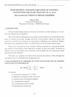
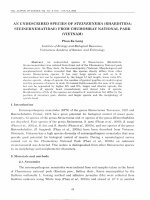
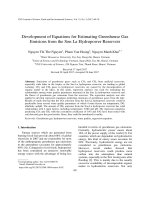
Fig. 3. EDX spectrum of the InP NCs after purification.
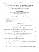
Fig. 1. X-ray diffraction patterns of InP NCs as a function of the reaction time: (a)
1 h, (b) 2 h and (c) 5 h (injection rate of NaBH4 : 1 mL min−1 ; reaction temperature
75 ◦ C).
NaBH4 (1 mL min−1 ) allowed for the suppression of the formation
of metallic In. Thus, in our further experiments these parameters
are considered to be the “normal conditions”.
Fig. 1 shows powder diffractograms of the InP NCs obtained
using these conditions while varying the growth time. For all three
samples, the XRD pattern is consistent with the cubic zinc-blende
structure of InP. The peak at 26.3◦ corresponds to the (1 1 1) lattice facet, with an atomic distance of 0.337 nm. The other peaks at
30.5◦ , 43.7◦ and 51.6◦ are indexed as the (2 0 0), (2 2 0) and (3 1 1)
reflexions, respectively. When the growth time was increased from
1 to 5 h, the InP NCs became only slightly bigger, as can be seen by
the almost imperceptible narrowing of the diffraction peaks. Using
the peak at 43.7◦ to calculate the mean crystallite size resulted in
∼4 nm (1 h) and 4.2 nm (5 h). In the following we will demonstrate
that the particle sizes determined by means of various methods are
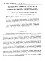
in good agreement. Fig. 2 shows the Raman spectrum of InP NCs
obtained after a reaction time of 2 h, using the 532 nm light from
a frequency-doubled Nd:YAG laser as the excitation source. The
transverse optical (TO) and longitudinal optical (LO) phonon lines
corresponding to the zinc-blende crystal structure of the InP NCs
Fig. 2. Raman scattering spectrum of the obtained InP NCs (reaction time 2 h). Their
mean size of 3–4 nm is estimated from the Raman shift and the intensity ratios
between the 2LO and LO lines.
are clearly visible [15,21]. It is noteworthy that both the TO and LO
Raman scattering lines could be observed because the NCs are randomly oriented; that is different from the case of bulk InP, in which
the recorded Raman spectra depend on the lattice facets under
measurement respecting the Raman scattering selection rule. By
comparing the recorded Raman spectrum to the reported sizedependent Raman spectra in Ref. [15], we estimate the size of our
InP NCs to be of 3–4 nm, which is in good agreement with the
crystallite size estimated from XRD measurements.
An EDX spectrum of a typical sample, which was washed several times with ethanol and toluene, and then with CS2 is shown in
Fig. 3. It reveals that the In:P atomic ratio is slightly smaller than
1 (0.96). Depending on the surface stoichiometry, a variation from
equimolar composition can be expected in NCs, exhibiting a high
surface:volume ratio. The observed excess of P is coherent with
the higher amount of phosphorus precursor used in the synthesis, which favours a P terminated surface. The presence of sulfur is
attributed to the washing of the sample with the CS2 solution.
The experimental results presented so far have proved that InP
NCs with a mean size around 4 nm have been synthesized with close
to equimolar stoichiometry. As mentioned previously, two ways for
injecting the NaBH4 solution were explored, termed “continuous
method” and “discontinuous method”. The results from XRD measurements and Raman spectroscopy are almost similar in the both
cases. However, some differences have been detected in the UV–vis
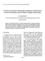
Fig. 4. UV–vis absorption spectrum of the obtained InP NCs (reaction time: 2 h),
after purification and subsequent dispersion in de-ionized water.
U.T.D. Thuy et al. / Materials Chemistry and Physics 112 (2008) 1120–1123
1123
temperature (70 ◦ C) is much lower than in most of the reported
procedures and nevertheless the produced particles show excellent
crystallinity, relatively low polydispersity and are obtained in high.
Their surface is not passivated by bulky organic molecules of surfactant type, in contrast to nanoparticles synthesized via traditional
colloid–chemical methods. Therefore charge transfer processes at
the interface with their surrounding medium are facilitated. By consequence, these NCs have a high potential for application in hybrid
organic/inorganic solar cells as broad-band light absorbers.
Acknowledgements
The authors thank Philippe Colomban (LADIR, CNRS France)
for his help in taking the Raman spectra. The Basic Research
Programme in Natural Science (MOST Vietnam) is gratefully
acknowledged for financial support. U.T.D.T. benefits from an
Evariste Galois stipend.
References
Fig. 5. TEM image of the obtained InP NCs. Left inset: HRTEM image of one particle
showing the distance between atomic layers (scale bar: 5 nm). Right inset: overview
image at higher magnification. The lattice planes of individual monocrystalline particles, highlighted with circles, are visible.
absorption spectra of both the types of samples. Only when the “discontinuous method” was used, a peak corresponding to the optical
transition in the expected near-band-edge region was distinguishable (Fig. 4), indicating a lower size distribution than in the case of
the “continuous method”. A more detailed analysis of the spectrum
is not possible due to the pronounced tail in the longer wavelength
region, which we attribute to light scattering arising from aggregates in the NCs dispersion. Fig. 5 displays the TEM image of InP
NCs obtained after a reaction time of 2 h. Individual NCs with sizes
ranging from 3 to 6 nm are forming larger aggregates. Due to the
superposition of the NCs, an accurate determination of the size distribution, estimated to be in the range of 15–20%, is delicate. The
high-resolution TEM image (inset of Fig. 5) shows that the interreticular distance of 3.348 Å concordates with the lattice distances
obtained from the XRD patterns (3.34–3.38 Å).
In conclusion, we have presented a simple method for the synthesis of InP NCs having a mean size of 3–4 nm. The reaction
[1] A.P. Alivisatos, Nat. Biotechnol. 22 (2004) 47.
[2] I.L. Medintz, H.T. Uyeda, E.R. Goldman, H. Mattoussi, Nat. Mater. 4 (2005)
435.
[3] N.C. Greenham, X. Peng, A.P. Alivisatos, Phys. Rev. B 54 (1996) 17628.
[4] W.U. Huynh, J.J. Dittmer, A.P. Alivisatos, Science 295 (2002) 2425.
[5] W.J.E. Beek, M.M. Wienk, R.A.J. Janssen, Adv. Mater. 16 (2004) 1009.
[6] Th. Andreev, E. Monroy, B. Gayral, B. Daudin, N.Q. Liem, Y. Hori, M. Tanaka, O.
Oda, L.S. Dang, Appl. Phys. Lett. 87 (2005) 021906.
[7] T. Wang, P.J. Parbrook, M.A. Whitehead, W.H. Fan, A.M. Fox, J. Cryst. Growth 273
(2004) 48.
[8] T. Andreev, N.Q. Liem, Y. Hori, M. Tanaka, O. Oda, L.S. Dang, B. Daudin, B. Gayral,
Phys. Rev. B 74 (2006) 155310.
[9] D. Lide, CRC Handbook of Chemistry and Physics, 73rd edition, CRC Press, 1993.
[10] C.B. Murray, D.J. Norris, M.G. Bawendi, J. Am. Chem. Soc. 115 (1993) 8706.
[11] J. Park, J. Joo, S.G. Kwon, Y. Jang, T. Hyeon, Angew. Chem. Int. Ed. 46 (2007) 4630.
[12] M. Green, Curr. Opin. Solid State Mater. Sci. 6 (2002) 355.
´ c,
´ C.J. Curtis, K.M. Jones, J.R. Sprague, A.J. Nozik, J. Phys. Chem. 98 (1994)
[13] O.I. Mici
4966.
´ c,
´ S.P. Ahrenkiel, A.J. Nozik, Appl. Phys. Lett. 78 (2001) 4022.
[14] O.I. Mici
´ c,
´ A.J. Nozik, A. Mascarenhas, H.M. Cheong, Appl. Phys. Lett.
[15] M.J. Seong, O.I. Mici
82 (2003) 185.
[16] D. Battaglia, X. Peng, Nano Lett. 2 (2002) 1027.
[17] A.A. Guzelian, J.E.B. Katari, A.V. Kadavanich, U. Banin, K. Hamad, E. Juban, A.P.
Alivisatos, R.H. Wolters, C.C. Arnold, J.R. Heath, J. Phys. Chem. 100 (1996) 7212.
[18] P. Yan, Y. Xie, W. Wang, F. Liu, Y. Qian, J. Mater. Chem. 9 (1999) 1831.
[19] B. Li, Y. Xie, J. Huang, Y. Liu, Y. Qian, Ultrason. Sonochem. 8 (2001) 331.
[20] B.D. James, M.G.H. Wallbridge, in: S.J. Lippard (Ed.), Progress in Inorganic Chemistry, vol. 11, John Wiley & Sons, Inc., London, New York, Sydney, 1970.
[21] L. Artus, R. Cusco, J.M. Martin, G. Gonzalez-Diaz, Phys. Rev. B 50 (1994) 11552.