DSpace at VNU: Geomagnetic sensors based on Metglas PZT laminates
Bạn đang xem bản rút gọn của tài liệu. Xem và tải ngay bản đầy đủ của tài liệu tại đây (892.15 KB, 5 trang )
Sensors and Actuators A 179 (2012) 78–82
Contents lists available at SciVerse ScienceDirect
Sensors and Actuators A: Physical
journal homepage: www.elsevier.com/locate/sna
Geomagnetic sensors based on Metglas/PZT laminates
D.T. Huong Giang ∗ , P.A. Duc, N.T. Ngoc, N.H. Duc
Department of Nano Magnetic Materials and Devices, Faculty of Engineering Physics and Nanotechnology, University of Engineering and Technology, Vietnam National University,
Hanoi, E3 Building, 144 Xuan Thuy Road, Cau Giay, Hanoi, Viet Nam
a r t i c l e
i n f o
Article history:
Received 21 November 2011
Received in revised form 19 March 2012
Accepted 19 March 2012
Available online 28 March 2012
Keywords:
Magnetic sensors
Geomagnetic sensors
Magnetoelectric effects
Multiferroics
a b s t r a c t
A potential geomagnetic-field sensor is proposed on the basis of an optimal 2D configuration of magnetoelectric Ni-based Metglas/PZT laminates. This sensor can perfectly serve to measure both the strength
and the orientation of the earth’s magnetic field. An incredibly high ME-voltage response of 0.871 V/Oe to
the geomagnetic field with a resolution of 3 × 10⁻⁴ Oe has been achieved for composite laminates with a
size of 15 mm × 1 mm. With respect to the field inclination, an angular sensitivity of 3.86 × 10⁻³ V/degree
and an angular resolution of 10−1 degree have been determined. This simple and low-cost magnetic-field
sensor is promising for applications not only as novel smart compasses and in global positioning devices,
but also as magnetic biosensors.
© 2012 Elsevier B.V. All rights reserved.
1. Introduction
The principle of global positioning is based on the fact that both
the strength and the inclination of the geomagnetic field is a welldefined function of the geographic position. The weak geomagnetic
fields, however, can only be detected with sensing devices of very
high sensitivity. Beside the traditional types of magnetic sensors on
the basis of fluxgate, Hall effect, superconducting quantum interference and giant magnetoresistance spin valves, such a sensor could
recently be realized thanks to the magnetoelectric (ME) effect [1–3].
This simple, low-cost sensor, furthermore, is featured by functioning at the room temperature.
The ME effect has been observed in multiferroics and/or
ferromagnetic-ferroelectric composites (hereafter denoted as ME
materials). In these materials, an electric polarization P in the
material shall respond to the applied magnetic field H, whereas a
magnetization M will respond to the applied electric field E. The
polarization process in an ME sample as response to the external applied magnetic field shall creates an electric field of E = ˛E ·H,
where ˛E (= dE/dH) denotes the magnetoelectric voltage coefficient.
As a result, a voltage VME = t·E (= ˛E ·t·H) appears between the surfaces of the sample of the thickness t. Large magnetoelectric voltage
coefficients offer potential device applications as highly sensitive
magnetic-field sensors, microwave filters, transformers, and gyrators [4].
∗ Corresponding author. Tel.: +84 4 3754 9665; fax: +84 4 3754 7460.
E-mail address: (D.T.H. Giang).
0924-4247/$ – see front matter © 2012 Elsevier B.V. All rights reserved.
doi:10.1016/j.sna.2012.03.030
Regarding the high magnetoelectric voltage coefficients, multiferroic composites on the basis of magnetostrictive ferrites and
rare earth-transition intermetallics have been studied intensively
since the beginning of this century [2,3,5–10]. In particular, operation principle, design and functioning characteristics of these new
ME sensors have also been described [2,3]. Values of magnetic field
response (dVME /dH) as high as 0.06 × 10⁻³ V/Oe, 56 × 10−3 V/Oe
and 13 × 10−3 V/Oe were reported for ME sensors using magnetostrictive Ni0.5 Zn0.5 Fe2 O3 ferrites [5], Terfenol-D laminates [6]
and Terfecohan thin films [7], respectively. In an approach to use
ME sensors for the determination of ac magnetic-field strengths,
Fetisov et al. [8] have successfully developed a promising sensor
with a sensitivity better than 10−3 Oe for milli-Hz frequency magnetic fields. Furthermore, strong efforts have been undertaken to
enhance the ME effects by altering the shape and the volume ratio of
the piezoelectric/magnetostrictive laminates [11] or by improving
the lamination process [12]. In the case of micro fabrication, Greve
et al. [13] reported a giant ME coefficient as high as 737 V/cm Oe
for (Fe90 Co10 )78 Si12 B10 -AlN thin film composites. Recently, an ME
sensor using Co-based Metglas/PZT laminates was designed, fabricated and characterized for determining the strengths as well as
the orientations of dc- and ac-magnetic fields [3], where an MEvoltage response (dVME /dH) of 2 × 10⁻³ V/Oe at low dc fields and, in
particular, a response (dVME /dhac ) as high as 17 × 10−3 V/Oe at the
low ac-ones was reported. These findings imply a great potential
for self-powered detection of low ac-magnetic fields.
For an optimal design of ME laminate sensors, modeling
approaches have been undertaken by several research groups
(e.g. [14–20]). While some models [15] have taken into account
the effect of the thickness ratio between the piezoelectric and
D.T.H. Giang et al. / Sensors and Actuators A 179 (2012) 78–82
79
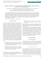
Fig. 1. Schematic of the bilayer (a) and sandwich (b) Ni-based Metglas/PZT composite configuration. Vector Hdc , hac and P shows the applied magnetic fields and the electrical
polarization direction, respectively.
magnetostrictive phases, other finite-element magnetostatic simulations [18–20] have considered the role of the magnetostrictive
length on the magnetic field concentration in ME sensors. Although
more appropriate descriptions of some specific aspects of sensor’s
behavior seem still necessary in the models, these results have
demonstrated a useful approach to significantly enhance the sensitivity of magnetostrictive/piezoelectric laminates as geomagnetic
field sensors.
In this paper, a potential geomagnetic sensor is presented by
optimizing the 2D configuration of the magnetoelectric Ni-based
Metglas/PZT laminates. At low dc-magnetic fields, a huge MEvoltage response as high as 0.871 V/Oe was obtained for the sensor
with size of 15 mm × 1 mm. The sensor is promising not only
for applications in novel smart compasses and global positioning
devices, but also in magnetic biosensors.
3. Results and discussion
3.1. Shape and size dependence of the resonant frequency
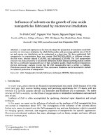
Fig. 2 shows the ac-magnetic-field-frequency dependence of the
ME coefficient ˛E measured under a fixed bias dc-magnetic field
of 4 Oe for the investigated square-shaped (r = 1) bilayer composite laminates of different sizes of 8 mm × 8 mm, 10 mm × 10 mm,
12 mm × 12 mm and 15 mm × 15 mm. The results show that with
the increasing laminate size, the resonance is shifted toward lower
frequencies (fr ), whereas ˛E significantly increases. The observed
phenomena can be described in term of the vibrating plates, in
which one of the natural frequencies (fnm ) of the modes is obtained
from the solution to the two-dimensional wave equation in Cartesian coordinates [21]:
fnm =
2. Experimental
The ME magnetic-field sensor was fabricated by bonding an
out-of-plane polarized piezoelectric PZT plate with magnetostrictive laminates. For this purpose, the 200-m-thick PZT plate
(APCC-855) of American Piezoceramics Inc., PA, USA was used.
The magnetostrictive laminates were cut from the 18-m-thick
Fe76.8 Ni1.2 B13.2 Si8.8 melt-spun ribbons (also called Ni-based Metglas) in different sizes according to the length-to-width ratio
(r = L/W), with r = 1, 1.5, 3, 7.5 and 15, and used for the various samples in this work. It is worth to note that the Ni-based Metglas
ribbon is a soft magnetostrictive material with a magnetostriction
coefficient ( ) of about 70 × 10−6 and a magnetostrictive susceptibility ( = d /dH) of 1.5 × 10⁻⁶ Oe−1 . Thanks to the mechanic
coupling between the components, the PZT plate undergoes a
forced strain induced by the magnetostrictive layers under the inplane (and/or out-of-plane) applied magnetic field. In this case,
the ME-voltage VME is induced across the thickness of the piezoelectric plate. Fig. 1 presents the configuration of such fabricated
bilayer Metglas/PZT and sandwich Metglas/PZT/Metglas ME composite laminates.
In the sample configurations under investigation, a linear electric polarization P is induced by a weak ac magnetic field hac
(= ho sin(2 fo t)) oscillating at the resonant frequency in the presence of a dc bias field H and the ME voltage VME is directly measured
as a response of the ME composite to the applied magnetic field. In
the experimental setup, the bias field H was provided by an electromagnet, and the oscillating field with amplitudes of hac = 10−2 Oe
was generated by a Helmholtz coil. The output voltage (VME ),
induced across the PZT layer of the ME laminate by the ac field (hac )
was measured on a commercial DSP lock-in amplifier (Model 7265
of Signal Recovery), which simultaneously controlled the input current to the Helmholtz coil. The value of the ˛E coefficient is derived
then from the equation: ˛E = VME /hac ·tPZT .
v
2
n2
m2
+ 2,
2
L
W
with v as the wave velocity in the PZT, n and m as integer numbers
(1, 2. . .).
Indeed, the experimental results are well fitted with a fundamental frequency f11 (i.e. with n = m = 1) (see Fig. 3). From this
description, the phase velocity turns out to be of 2800 m/s for PZT.
This finding is consistent with that reported for the piezoelectric
bulk material. For sandwich Metglas/PZT/Metglas structures, the
ME effect can be remarkably increased, while the resonant frequency exhibits no change.
As regards to the shape effect, in this paper, rectangular
composite laminates with different length to width ratios were
investigated. For the fabrication of the investigated samples, its
longitudinal edge (the length L) was kept fixed at 15 mm while
its transversal edge (the width W) was varied from 1 to 15 mm,
Fig. 2. ME coefficient as a function of the ac magnetic field frequency for squareshaped samples.
80
D.T.H. Giang et al. / Sensors and Actuators A 179 (2012) 78–82
Fig. 5. The magnetic field dependent of ME coefficient for 8 mm × 8 mm,
12 mm × 12 mm and 15 mm × 15 mm bilayer square-shaped samples.
Fig. 3. Resonant frequency vs.
(1/W 2 ) + (1/L2 ) for square-shaped bilayer com-
posites of different sizes L × W.
so that a series of rectangular laminate samples was obtained
with the respective length/width ratios (r = L/W) varying from 15
to 1. The respective values of the resonant frequency fr , obtained
for these samples are shown in Fig. 4 for the case the magnetic
fields are applied along the length of samples. It is interesting that,
except the square-shaped sample (with r = 1), all composite laminates exhibit an invariant fr of about 100 kHz, which is nearly 1.5
times lower than that observed for the sample with r = 1. By using
the above extracted wave velocity, the measured resonant frequencies of the rectangular composite laminates are well fitted with the
fundamental frequencies of the one-dimensional wave equation
f10 = v/2L. In this case, the resonant frequency is ascribed as mainly
governed by the longitudinal length of the sample.
3.2. Shape and size dependence of the ME coefficient
Fig. 5 shows the bias-field dependence of the ME coefficient
for the different investigated square-shaped samples measured
at the resonant frequencies. As can be seen, for all samples the
magnetoelectric coefficient exhibits a similar behavior: it initially
increases at low applied magnetic fields, reaches a maximum value
Fig. 4. Resonant frequency vs. the ratio of the length to the width r (= L/W) for bilayer
ME composites. The fitted line f10 = v/2L is shown.
at a certain magnetic field (denotes as the optimal field for the
maximal ME response) and then decreases with further increasing magnetic field. It is apparent that the value of ME coefficient
is strongly influenced by the sample size: the larger the interfacial area (i.e. the sample size), the lower the optimal magnetic
field, the higher the ME voltage coefficient and, consequently, the
higher the initial slope at low magnetic fields is found for the ˛E (H)
curves. This observation can be understood in term of the so-called
“shear lagging” edge effect [22]. Furthermore, a huge ME coefficient of 75.9 V/cm Oe is found at low bias field of only 10 Oe in
the composite laminate with r = 1. By using the sandwich Metglas/PZT/Metglas laminate structures, the ME effect can increase up
to ˛E = 132.1 V/cm Oe. Although this value is about 5 times lower
than the highest ME coefficient reported for (Fe90 Co10 )78 Si12 B10 AlN thin film by Greve et al. [13], the composite laminates fabricated
with a simple and low-cost technology in this work suggest a very
promising application in practical sensors.
With the motivation to further enhance the low-field ME voltage
coefficient, rectangular-shape composite laminates with various
length/width ratios have been prepared and investigated. This
motivation is based on the fact that the enhancement of magnetoelectric softness is related to the shape anisotropy. Fig. 6
shows the ME coefficient ˛E as a function of the dc-magnetic field
strength for sandwich composite laminates of different sizes as
15 mm × 15 mm, 15 mm × 3 mm and 15 mm × 1 mm, corresponding to the respective length/width ratios of r = 1, 5 and 15. The
measurements were carried out with the magnetic fields applied
Fig. 6. The ME coefficient as a function of bias magnetic field for rectangular-shaped
sandwich Metglas/PZT/Metglas composites of different sizes 15 mm × 15 mm,
15 mm × 3 mm and 15 mm × 1 mm.
D.T.H. Giang et al. / Sensors and Actuators A 179 (2012) 78–82
81
Fig. 9. The output ME voltage as a function of bias magnetic field for sensor prototype. The fitted curve is included.
Fig. 7. ME coefficient measured at Hdc = 2 Oe (open square) and maximum ME coefficient (close circle) as a function of the length to the width ratio (L/W).
along the length of the sample. The results show that the maximal ME coefficient is significantly unchanged in samples with high
r values (remaining significantly at 131 V/cm Oe, obtained for the
sample with r = 15, see Fig. 7). The optimal magnetic field for the
maximal ME response, however, strongly decreases from 21 Oe
in the sample with r = 1 to 7 Oe in the sample with r = 15. Consequently, the much higher initial slope at low-magnetic fields of the
˛E (H) curves is observed. This important behavior is illustrated in
Fig. 7 with the data measured in an applied field of 2 Oe. The highest
ME coefficient of 62.61 V/cm Oe has been found in the sample with
length to width ratio r = 15. As will be presented in the next section,
for practical geomagnetic sensor applications, the optimal size of
15 mm × 1 mm (i.e. r = 15) could be chosen for sensor prototypes.
3.3. Geomagnetic sensor prototype
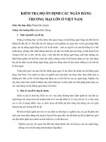
Fig. 8 shows photographs of the ME composite laminates and
a geomagnetic sensor prototype fabricated using an ME composite laminate with optimal rectangular size of 15 mm × 1 mm. A
solenoid coil is wrapped around the ME composite laminate to generate the ac-magnetic field at the resonant frequency. The effective
field is by this way aligned in-plane and along the length of the
ribbons (i.e. perpendicular to the electrical polarization of the PZT
plate). For testing the sensor operation in the range of the geomagnetic field strength, a Helmholtz coil supplied by a Keithley 230
current source was used to generate the bias magnetic fields in the
range up to 1.5 Oe with the accuracy of 10−5 Oe.
Shown in Fig. 9 is the ME voltage response to the external
magnetic field. As can be seen, a linear variation of the MEvoltage with the external magnetic field has been found in the
field range up to 1.0 Oe. From this result, the sensor sensitivity
could be derived as high as 0.871 V/Oe. In a more detailed analysis,
the field resolution of 3 × 10⁻⁴ Oe has been estimated. Surprisingly, the present ME-based sensor exhibits a sensitivity, which
is two orders of magnitude higher than that previously reported
for similar magnetic-sensor devices and is comparable with that of
available commercial geomagnetic sensors [23]. This configuration
presents a good combination of the excellent magnetic softness of
Ni-based Metglas ribbons and the effects of the shape anisotropy.
This sensor enables to detect not only the geomagnetic fields, but
also the magnetic fields of magnetic micro- and nano-beads in
biochip applications.
Regarding the application of the proposed sensor in determining
the orientation of the Earth’s magnetic field, another experimental
setup is illustrated in Fig. 10(a). Shown in Fig. 10(b) is the sensor output voltage as a function of the ϕ-angle between the sensor
axis, i.e. the axis in the plane along the length of the laminate. The
zero angle (ϕ = 0◦ ) is defined when the sensor is in such a position that its axis is aligned parallel to the Earth’s North magnetic
Pole. It is clearly seen from this figure that by rotating the sensor in
horizontal plane from ϕ = 0–360◦ , the sensor signal varies periodically with ϕ, reaching a maximum value of 356 mV in the parallel
Fig. 8. Sensor construction: Ni-based Metglas/PZT 15 mm × 1 mm laminates (a) and sensor prototype where the coil generating an ac field directly wraps around the ME
laminate (b).
82
D.T.H. Giang et al. / Sensors and Actuators A 179 (2012) 78–82
Fig. 10. Experimental setup for measuring orientation of the Earth’s magnetic field
(a) and the output signal as a function of ϕ-angle between the sensor’s longitudinal
axis and the Earth’s North magnetic Pole (b).
alignments (i.e. ϕ = 0 and 180◦ ) and vanishing in the perpendicular alignments (i.e. ϕ = 90 and 270◦ ) of the sensor axis with respect
from the North-South direction of the Earth’s magnetic field. This
finding suggests that the fabricated sensor can be used for detecting
both the strength and the orientation of the geomagnetic field.
4. Concluding remarks
The composite laminate configuration combining high performance Ni-based Metglas ribbons and piezoelectric PZT plates has
brought by an optimal giant magnetoelectric effect with a significant ME coefficient in the low magnetic field range. A potential
geomagnetic-field sensor is prepared on the basis of the optimal
laminate configuration. The sensor can detect precisely not only
the strength, but also the orientation of the Earth’s magnetic field.
A high sensibility of 0.871 V/Oe and a resolution in the order of
10−4 Oe without amplification make this configuration a potential sensor for applications in novel smart compasses and global
positioning devices.
Acknowledgements
This work was supported by Vietnam National University, Hanoi
under the granted Research Project QG 09.29, by the NAFOSTED of
Vietnam under the Research Project Number 103.02.86.09 and by
the National Program for Space Technology of Vietnam. The authors
thank Assoc. Prof. Dr. N.T. Hien from the VNU University of Engineering and Technology for critical reading of the manuscript.
References
[1] J. Zhai, S. Dong, Z. Xing, J. Li, D. Viehland, Geomagnetic sensor based on giant
magnetoelectric effect, Appl. Phys. Lett. 91 (2007) 123513.
[2] N.H.
Duc,
D.T.
Huong
Giang,
Magnetic
sensors
based
on
piezoelectric–magnetostrictive composites, J. Alloys Compd. 449 (2008)
214.
[3] D.T. Huong Giang, N.H. Duc, Magnetoelectric sensor for microtesla magneticfields based on (Fe80 Co20 )78 Si12 B10 /PZT laminates, Sens. Actuator A 149 (2009)
229.
[4] T.H. O’Dell, Magnetoelectrics – a new class of materials, Electron Power 11
(1965) 266.
[5] L.P.M. Bracke, R.G. van Vliet, A broadband magneto-electric transducer using a
composite materials, Int. J. Electron. 51 (1981) 255.
[6] B.J. Linch, H.R. Gallantree, A new magnetic sensor technology, GEC J. Res. 8
(1990) 13.
[7] M.I. Bichurin, V.M. Petrov, R.V. Petrov, Y.U.V. Kiliba, F.I. Bukashev, A.Y.U.
Smirnov, D.N. Eliseev, Magnetoelectric sensor of magnetic field, Ferroelectric
280 (2002) 199.
[8] Y. Fetisov, A. Bush, K. Kamentsev, A. Ostashchenko, G. Srinivasan, Ferritepiezoelectric multilayers for magnetic field sensors, IEEE Sens. J. 6 (2006)
935.
[9] J. Ryu, S. Priya, K. Uchino, H. Kim, D. Viehland, High magnetoelectric properties
in 0.68Pb(Mg1/3 Nb2/3 )O3 -0.32PbTiO3 single crystal and Terfenol-D laminate
composites, J. Kor. Ceram. Soc. 9 (2002) 813.
[10] J. Ryu, S. Priya, K. Uchino, H. Kim, Composites of magnetostrictive and piezoelectric materials, J. Electroceram. 8 (2002) 107.
[11] J. Blackburn, M. Vopsaroiu, M.G. Cain, Composite multiferroics as magnetic field
detectors: how to optimise magneto-electric coupling, Adv. Appl. Ceram. 109
(2010) 169.
[12] M. Li, D. Berry, J. Das, D. Gray, J. Li, D. Viehland, Enhanced sensitivity and reduced
noise floor in magnetoelectric laminate sensors by an improved lamination
process, J. Am. Ceram. Soc. 94 (2011) 3738.
[13] H. Greve, E. Woltermann, H.-J. Quenzer, B. Wagner, E. Quandt, Giant magnetoelectric coefficients in (Fe90 Co10 )78 Si12 B10 -AlN thin film composites, App. Phys.
Lett. 96 (2010) 182501.
[14] S.X. Dong, J.F. Li, D. Viehland, Longitudinal and transverse magnetoelectric voltage coefficients of magnetostrictive/piezoelectric laminate composite: theory,
IEEE Trans. Ultrason. Ferroelectr. Freq. Control 50 (2003) 1253–1261.
[15] C.W. Nan, M.I. Bichurin, S.X. Dong, D. Viehland, G.J. Srinivasan, Multiferroic
magnetoelectric composites: historical perspective, status and future directions, J. Appl. Phys. 103 (2008) 031101.
[16] R. Corcolle, L. Daniel, F. Bouillault, Modeling of magnetoelectric composites
using homogenization techniques, Sens. Lett. 7 (2009) 446–450.
[17] T.T. Nguyen, F. Bouillault, L. Daniel, X. Mininger, Finite element modeling of
magnetic field sensors based on nonlinear magnetoelectric effect, J. Appl. Phys.
109 (2011) 084904.
[18] Z. Fang, S.G. Lu, F. Li, S. Datta, Q.M. Zhang, M. El Tahchi, Enhancing the magnetoelectric response of Metglas/polyvinylidene fluoride laminates by exploiting
the flux concentration effect, Appl. Phys. Lett. 95 (2009) 112903.
[19] J. Gao, D. Gray, Y. Shen, J. Li, D. Viehland, Enhanced dc magnetic field sensitivity
by improved flux concentration in magnetoelectric laminates, Appl. Phys. Lett.
99 (2011) 153502.
[20] X.X. Cui, S.X. Dong, Theoretical analyses on effective magnetoelectric coupling
coefficients in piezoelectric/piezomagnetic laminates, J. Appl. Phys. 109 (2011)
083903.
[21] W.C. Elmore, M.A. Heald, Physics of Waves, Dover Publications, New York, 1985.
[22] C.M. Chang, G.P. Carman, Modeling shear lag and demagnetization
effects in magneto-electric laminate composites, Phys. Rev. B 76 (2007)
134116.
[23] M. Johnson, Magnetoelectronics, Elsevier, Amsterdam, 2004.
Biographies
D.T. Huong Giang received her PhD degree in Physics from the Rouen University,
France in 2005. In 2006, she joined the Faculty of Engineering Physics and Nanotechnology at VNU University of Engineering and Technology, Vietnam National
University, Hanoi, where she is currently an assistant professor. Her research
interests include magnetostrictive, magnetoresistance, magnetoelectric and multiferroics materials, sensors and microsystems.
P.A. Duc received his BSc and MSc degree in Physics from Hanoi National University
in 2004 and 2007, respectively. He is currently working on his PhD dissertation in
the area of magnetoelectric composites and applications.
N.T. Ngoc has studied at the University of Engineering and Technology, Vietnam
National University, Hanoi and is finishing her master in Nanotechnology. She is
developing 3D-sensor for geomagnetic applications.
N.H. Duc joined the Cryogenic Laboratory, University of Hanoi as researcher after
his graduation from the same group in 1980. He obtained his doctor degree in the
same group in 1988. He has then received the French Habilitation in Physics at the
Joseph Fourier University of Grenoble in 1997 and became a full professor of the College of Technology (now VNU University of Engineering and Technology), Vietnam
National University, Hanoi in 2004. His extended research includes various aspects
of magnetism, such as: 4f–3d exchange interactions; giant magnetovolume, magnetostrictive, magnetoresistive and magnetocaloric effects; magnetic phase transition;
magnetic nanostructures; multiferroics; MERAM and biochips.