DSpace at VNU: Copper-Filled Through-Silicon Vias With Parylene-HT Liner
Bạn đang xem bản rút gọn của tài liệu. Xem và tải ngay bản đầy đủ của tài liệu tại đây (2.4 MB, 8 trang )
This article has been accepted for inclusion in a future issue of this journal. Content is final as presented, with the exception of pagination.
IEEE TRANSACTIONS ON COMPONENTS, PACKAGING AND MANUFACTURING TECHNOLOGY
1
Copper-Filled Through-Silicon Vias
With Parylene-HT Liner
Tung Thanh Bui, Naoya Watanabe, Member, IEEE, Xiaojin Cheng, Fumiki Kato,
Katsuya Kikuchi, Member, IEEE, and Masahiro Aoyagi
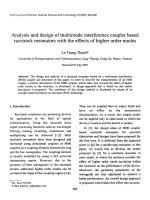
Abstract— Organic low-k materials have been considered
in the literature for satisfying the requirements of lowering
the dielectric constant of the dielectric layer to decrease the
problem of signal delay, lower power consumption, and to reduce
cross talk between the neighboring paths, and lowering the
fabrication temperature budget. In this paper, the feasibility
of using Parylene-HT as a low-temperature deposition, highuniformity coverage low-dielectric liner for copper-filled throughsilicon vias (TSVs) in 3-D integration is investigated. In particular,
the capability of embedding Parylene-HT in via-last fabrication
process is validated through the demonstration of 100-µm-depth
bottom-up copper-filled TSVs. TSVs with Parylene-HT as a liner
were realized through vias etching, parylene vapor deposition,
and copper electroplating processes. The Parylene-HT deposition
and copper electroplating processes were implemented at room
temperature, such that thermal-related issue would be avoided
and device reliability would be enhanced. The insulation function
of the Parylene-HT liner of the fabricated TSVs was characterized. Capacitance of 0.164 pF/TSV and leakage current density
of 22 pA/cm2 at a field of 0.25 MV/cm were obtained through
the measurement of the TSV arrays. The obtained results reveal
the possibility of using such a high potential parylene in lowtemperature budget 3-D integration applications.
Index Terms— Copper-filled TSV, low-k liner, Parylene-HT,
via-last process.
I. I NTRODUCTION
D
RIVEN by More than Moore, various 3-D interconnection technologies are emerging and playing important roles in furthering electronics miniaturization [1], [2].
In the last decades, through-silicon-via (TSV) processes have
intensively been investigated for vertically stacked 3-D semiconductor devices. The TSV technology has become a
promising candidate for 3-D integration in many prospective
applications, and its market is gradually growing up, not
only in the high-performance area but also in the area
of high-volume devices, such as consumer devices [3].
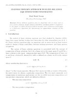
Manuscript received October 27, 2015; accepted December 24, 2015.
This work was supported by the New Energy and Industrial Technology
Development Organization. Recommended for publication by Associate Editor
G. Refai-Ahmad upon evaluation of reviewers’ comments.
T. T. Bui is with the National Institute of Advanced Industrial Science and
Technology, Tsukuba 305-8560, Japan, and also with the Faculty of Electronics and Telecommunication, University of Engineering and Technology,
Vietnam National University, Hanoi, Vietnam (e-mail: ).
N. Watanabe, F. Kato, K. Kikuchi, and M. Aoyagi are with the National
Institute of Advanced Industrial Science and Technology, Tsukuba 305-8560,
Japan (e-mail: ; ; k-kikuchi@aist.
go.jp; ).
X. Cheng is with Loughborough University, Loughborough LE11 3TU, U.K.
(e-mail: ).
Color versions of one or more of the figures in this paper are available
online at .
Digital Object Identifier 10.1109/TCPMT.2016.2521682
Fig. 1.
Schematic of a 3-D integrated LSI system using copper-filled TSV.
Various materials are being considered for replacing copper
as a filling material for cost effective using solder
materials [4], [5] or for enhancing TSV performance using
single-walled/multiwalled carbon nanotubes [6]–[8]. Alternative TSV structures have been proposed for stress reduction
to improve device reliabilities [9]–[11]. Owing to the low
electrical resistivity, high stress migration resistance, and
high melting point, the copper-filled TSVs (Fig. 1) are the
most common and cost-effective mass producible TSVs [1].
However, with the aggressive scaling down of the interconnect
system for higher integrity and better performance, the requirement for lowering the dielectric constant of the dielectric
layer to decrease the problem of signal delay, lower power
consumption, and to reduce cross talk between neighboring
paths is given.
Nevertheless, there are technological challenges to
implement the integration process for 3-D ICs within a low
thermal budget to reduce the impact on CMOS devices.
Low-temperature process would help in reducing the processinduced thermal stress issue arising from the mismatch of
thermal expansion between constituent materials that could
cause serious issues, such as Si cracking, which subsequently
cause device failure and performance degradation of
devices [12]. Thanks to the excellent mechanical properties,
polymer low-k materials can act as an internal stress buffer
layer and can reduce the residual stress within the TSV
structure [13], [14]. Low-temperature reliable Au microbump
interconnections with submicrometer range bonding accuracy
which are based on self-aligned interconnection elements and
flip-chip bonding approach for low-temperature compatible
3-D integration [15]–[18]. For the TSV formation, the lowtemperature formation of TSV is focused in order to realize
3-D integration within a low thermal budget.
It is critical to find appropriate materials as the insulation
layer between copper and Si that not only offer excellent
dielectric and mechanical properties but are also able to
2156-3950 © 2016 IEEE. Personal use is permitted, but republication/redistribution requires IEEE permission.
See for more information.
This article has been accepted for inclusion in a future issue of this journal. Content is final as presented, with the exception of pagination.
2
IEEE TRANSACTIONS ON COMPONENTS, PACKAGING AND MANUFACTURING TECHNOLOGY
Fig. 3.
Chemical structures for (a) different types of parylene
and (b) deposition process of Parylene-HT.
Fig. 2.
Deposition of (a) Tetraethoxysilane (TEOS) SiO2 and (b) and
(c) Parylene-HT on the sidewall of Si vias. SiO2 deposited by CVD-TEOS,
showing the difficulty in creating reliable TSV’s oxide liner.
withstand various thermal conditions during fabrication.
Polymer low-k materials have been considered to meet these
desires. Moreover, using a polymer buffer layer, the thermal
stress in the TSV structure can considerably be reduced [13],
and the electrical performance can be improved by reducing
the capacitive coupling. Parylene has several distinct advantages over other polymer materials, Kapton, and polyimide
materials [19]–[21]. Parylene has a low dielectric constant,
excellent electrical insulation, high dielectric strength, and
high mechanical durability, and it can be deposited on many
substrates, such as silicon, glass, metal, plastics, and ceramic,
in the form of a conformal thin film. It is deposited under
vacuum at room temperature by means of vapor phase. As the
entire process can be implemented at room temperature,
stresses generated from different thermal expansion coefficients between the temperature of cure and the room temperature, as would be the case in some of other cured polymers,
are avoidable. Besides, parylene facilitates a good conformal
coverage of the sidewall not only on the surface of the wafers
but also inside the vias of different dimensions (Fig. 2).
In addition, it can be patterned by dry techniques, such as
plasma etching, reactive ion beam etching, reactive ion etching, or high-density plasma etching [22]–[26]. Hence, it has
been investigated to be used for 3-D interconnect applications.
Parylene-N has been investigated at IMEC as an insulation
layer in the TSV structures [27]. Parylene-C has also been used
in the process of TSV copper electroplating filling, as a sidewall protection to ensure bottom-up filling of blind TSV [28].
By incorporating fluorine atoms in the place of hydrogen
aliphatic atoms, Parylene-HT, the newest parylene material
presents the advantages of the lowest dielectric constant
(1.17–2.21) and the highest temperature withstanding (short
term up to 450 °C) among the commercially available variant
of Parylene-N, Parylene-C, Parylene-D, and Parylene-HT [29].
By means of vapor-phase polymerization at low temperatures
(i.e., 25 °C), Parylene-HT would be a promising candidate for
use with via-last TSV liner.
The aim of this paper is to investigate the feasibility of
using Parylene-HT for 3-D interconnection. The initial results
on utilizing Parylene-HT as a TSV liner have been reported
in [30]–[32]. In this paper, a complete data set of fundamental
investigations on the diffusion of copper in Parylene-HT and
the capability of embedding Parylene-HT into back-end-ofline (BEOL) TSVs will be summarized and reported in detail.
Results and discussions on realizing copper-filled TSVs with
Parylene-HT liner on 100-μm-thick p-type Si wafer and their
electrical properties will also be presented.
II. PARYLENE -HT AS A D IELECTRIC L AYER
FOR 3-D I NTEGRATION
A. Parylene-HT Deposition Process
The chemical structures of the common types of parylene
(Parylene-N, Parylene-C, and Parylene-D) and Parylene-HT
are shown in Fig. 3(a). Parylene-HT, similar to other parylenes
(poly-p-xylylene), is a polymeric film. It is chemical vapor
deposited (CVD) by a process, as schematically shown
in Fig. 3(b). Parylene dimer [di(poly-p-xylylene)] is vaporized
at about 150 °C, pyrolized to the monomer poly-p-xylylene at
about 680 °C, and then deposited at 25 °C. The mechanism of
deposition begins with the condensation of parylene monomer
on and diffusion to the surface, followed by chain initiation
and propagation, in which the monomer molecules form
long polymer chains [33]. Since polymerization is preceded
by condensation, the parylenes are highly transparent and
conformal, and have pinhole-free coatings over large surface
areas. Some mechanical, thermal, and electrical properties
This article has been accepted for inclusion in a future issue of this journal. Content is final as presented, with the exception of pagination.
BUI et al.: COPPER-FILLED TSVs WITH PARYLENE-HT LINER
3
TABLE I
M ECHANICAL , T HERMAL , AND E LECTRICAL P ROPERTIES OF PARYLENE -HT C OMPARED W ITH C ONVENTIONAL L INERS
of Parylene-HT compared with other common parylenes and
the two dielectrics, which have been the workhorse of the
semiconductor industry, are listed in Table I.
In this paper, 1-μm-thick Parylene-HT was coated on
Si substrates by a parylene deposition system (PDS 2060,
Specialty Coating Systems, Inc.). The uniformity of
parylene-HT on the surface of the wafers after the deposition was measured using a surface profilometer. The roughness of parylene surface was inspected by a scanning probe
microscopy. Pinhole-free, 1.05 μm-thick Parylene-HT layers
deposited on 3-in Si wafers at 25 °C, with an average roughness value of Ra = 4.402 nm, were obtained. Moreover, the
adhesion between the Parylene-HT and the Si substrate was
tested according to the testing methods of ISO2409/JIS K5600.
It was performed by stripping off a pressure sensitive tape
at 90° angle, which has first been attached firmly on the
surface of a specimen after cross cutting at 1-mm intervals.
The obtained results implied that none of the squares of the
lattice were detached, confirming that the Parylene-HT was
well deposited on Si substrate [30]. This would qualify for
the electroplating process. In the next part, the diffusion of
copper in these parylene films at different temperatures will
be presented.
B. Copper Diffusion in Parylene-HT
Copper is known to be quite easy to diffuse into
another material, and it can diffuse into Si and SiO2 to
form copper silicide compounds at temperatures of around
200 °C [34]–[37]. For that reason, barrier materials, such as
TaN, Ta, Ti, TiN, W, and so on, have to be used to prevent
Cu atoms from diffusing into either dielectric materials or
Si substrates [38]–[40]. Therefore, the diffusion of copper in
Parylene-HT needs to be addressed to estimate the possibility
of using this parylene as a liner for copper-filled TSV.
The diffusivity of copper in Parylene-HT is examined using
a depth-profiling technique. Samples for investigating the
diffusion of copper in Parylene-HT are prepared, as shown
in Fig. 4(a). On a substrate coated with 1 μm of Parylene-HT,
500-nm copper was deposited by sputtering. These samples
were then annealed at temperatures up to 350 °C, i.e., the
thermal budget of the most BEOL processes, for different
periods. After that, the top copper layer was wet-etched
to expose the parylene surface to the analyzing beam for
copper diffusion inspection through depth profile obtained by
secondary ion mass spectrometry (SIMS) [41].
Fig. 4. Diffusion of copper in Parylene-HT. (a) Sample preparation procedure
for SIMS analysis. (b) SIMS analysis as deposition sample and being annealed
at different temperatures. (c) HR-TEM image and (d) EELS analysis of the
sample annealed at 250 °C for 48 h.
The diffusion depth of copper was examined using
ADEPT-1010 (LVAC-PHI, Inc.,) with Cs primary ion bombardment (acceleration voltage of 1 kV and system vacuum
of 1E-11 Pa). The sputter crater depth was measured by a
profilometer to convert the time axis to depth. It was confirmed
that the Parylene-HT did not degas under the high vacuum
conditions during the SIMS sputtering process. A crater depth
of 160 nm was measured. The depth profile of a nonannealing sample was used as a reference, and copper diffusion
depths were determined through the comparison of the copper
depth profile of nonannealing and annealed samples at different annealing conditions [Fig. 4(b)]. The results reveal that
Cu atoms are difficult to be diffused into the Parylene-HT
in the temperature ranges of interest. The diffusion depths
are estimated to be 10 and 12 nm, which correspond to the
annealing conditions of 250 °C for 24 h and 350 °C for 3 h,
respectively.
The diffusion coefficient at these given temperatures
can be extrapolated from the experimental results. As a
500-nm-thick copper layer is deposited on the top of the
parylene film, a constant-surface-concentration boundary can
This article has been accepted for inclusion in a future issue of this journal. Content is final as presented, with the exception of pagination.
4
IEEE TRANSACTIONS ON COMPONENTS, PACKAGING AND MANUFACTURING TECHNOLOGY
Fig. 6. Process flow to realize TSV with Parylene-HT liner for electrical
properties characterization.
Fig. 5. Via-last/backside-via blind TSV approach for 3-D IC integration.
Vias are formed after BEOL.
be applied for Flick’s diffusion equation for having [42]
x
√
(1)
2 Dt
where erfc is the complementary error function, x is the
coordinated axis in the direction of flow, Cs is the constant
surface concentration. D and t are the diffusion coefficient
and diffusion time, respectively. Diffusion depth d can be
expressed as
√
d = Dt.
(2)
C(x, t) = Cs erfc
Using (2), the diffusivities corresponding to 250 °C and
350 °C are calculated to be 5.7E-18 and 1.3E-16 cm2 /s,
respectively.
High-resolution
transmission
electron
microscopy (HR-TEM) and electroenergy loss spectroscopy (EELS) analyses were also utilized to confirm these
results [Fig. 4(c) and (d)].
As is well known, the integration of copper wiring with
silicon dioxide requires barrier encapsulation, since the diffusion coefficient of Cu atoms is quite high in silicon or
silicon oxide, i.e., about 1E-12 cm2 /s at 350 °C [43]. The
diffusivities of copper in Parylene-HT were noticed to be much
lower; in addition to the ability of deposition in micrometerorder thickness, this enables the use of Parylene-HT as a liner
layer for TSV without any barrier layer. In the next part,
Cu-filled TSVs with Parylene-HT as a liner realized using
via-last processes will be demonstrated.
III. C OPPER -F ILLED TSV W ITH PARYLENE -HT L INER
A. Fabrication Process
A 3-D IC integration approach using via-last TSV, in which
TSVs are fabricated through via etching, liner deposition, and
contact hole opening, followed by barrier deposition, metal
filling, and CMP, is shown in Fig. 5. For demonstrating
the compatibility of employing Parylene-HT in the via-last
process, bottom-up copper-filled TSVs with Parylene-HT as
a liner were fabricated on a 100-μm-thick silicon wafer by a
fabrication process, as shown in Fig. 6.
First, a 100-μm-thick Si substrate is temporarily bonded
to a carrier glass wafer for thin wafer handling. Then, vias
are etched by BOSCH etching process. AZP-4620 photoresist
with a hexamethyl disilizane adhesion promoter was used
as an etching mask for the BOSCH process. Carrier glass
wafer was debonded, and the substrate was cleaned, as shown
in Fig. 6(a)–(d).
After that, Parylene-HT is deposited on the substrate,
under vacuum at room temperature by means of vapor phase
[Fig. 6(e)]. Cleaning steps are taken with care for having a
clean surface, promoting the adhesion between Parylene-HT
and Si. Parylene-HT with the thickness of approximately 1 μm
is coated on Si substrates by a parylene deposition system
(PDS 2060, Specialty Coating Systems, Inc.). The uniformity
of Parylene-HT on the surface of the wafer after the deposition
is confirmed using a surface profilometer.
Dry photoresist film (MXA115) with a thickness of 15 μm
followed by a 15 μm-thick copper foil is laminated on
the backside of the substrate. Then, the dry film is selectively etched to expose the copper seed layer in the vias
[Fig. 6(f)–(i)].
The diffusivities of copper into Parylene-HT, which was
examined using depth-profiling technique, as mentioned earlier, were implied to be low [41]. Hence, no barrier encapsulation layer was used in this fabrication process. The parylene
surface is treated with oxygen plasma for surface modification
and followed by electroplating for copper filling [Fig. 6(j)]
at 25 °C. After the electroplating process, the copper overburdens are then removed, and the electrical properties of the
fabricated TSV are characterized.
As the parylene deposition and electroplating processes
were implemented at room temperature, stresses from the
difference in the coefficient of thermal expansion between
constituting materials during the change of deposition/curing
and room temperature, which would be the case of the
other polymers, can be avoided. This would contribute to the
enhancement of device reliability and manufacturing yield.
Fabrication results are shown in Fig. 7. Vias with different
diameters are shown in Fig. 7(a)–(c). The process of plasma
oxide deposition to achieve on the sidewall of deep Si via in
the range of micrometer is challenging, in regard to obtaining
This article has been accepted for inclusion in a future issue of this journal. Content is final as presented, with the exception of pagination.
BUI et al.: COPPER-FILLED TSVs WITH PARYLENE-HT LINER
5
Fig. 7. Fabrication results. (a)–(c) After etching process. (d) and (e) After
parylene deposition process. (f) and (g) After copper electroplating process.
Fig. 8.
(a) Equivalent circuit of the TSV and measurement setup for
measuring (b) TSVs capacitance and leakage current, and (c) resistance.
high step coverage or low deposition temperature [44], [45].
Parylene-HT layer with a thickness of approximately 1 μm
was deposited successfully at room temperature on via’s
sidewall [see Fig. 7(d) and (e)]. No pinhole was observed,
and high uniformity was confirmed.
Fig. 7(f) and (g) shows the scanning electron microscope
images of copper-filled TSVs with Parylene-HT as liner material. The top view in Fig. 7(f) and cross-sectional view in
Fig. 7(g) indicate that copper was filled well into the vias
through electroplating process. As can be observed, no seams
or voids were observed. Fundamental electrical properties of
the fabricated TSVs with the copper diameter of 34 μm,
i.e., AR = 3, including capacitance, resistance, and leakage
current, were examined, and the results will be presented in
the following part.
capacitance of TSVs were measured through a probing
system. Experimental setups for TSV resistance and insulation capacitance are shown in Fig. 8(b) and (c), respectively. Since the diameter of the TSV is tiny, a nanoprober
(N-6000, Hitachi) was used for probing on TSV cap for the
resistance the measurement. The cross-sectional view of the
TSV structure with a four-point-resistance measurement is
schematically shown in Fig. 8(c). The resistance RTSV and
capacitance CTSV of the TSV can be estimated as
ρmetal
h
(3)
RTSV =
2
π D2 − t
B. TSV’s Electrical Properties
Since copper electroplating was controlled to allow copper
to fill up the vias and reach the wafer surface, the electrical
properties of TSVs can be characterized directly. The crosssectional view of the TSV structure with equivalent circuit
is shown in Fig. 8 schematically, including the insulator
capacitance and leakage current phenomena. The electrical
behavior of a TSV can be examined using an MIS structure [46], in which the copper pillar acts as a signal path
and Parylene-HT acts as an insulator surrounding to block
dc leakage from copper pillar to Si substrate. Si substrate
used in this paper is of the p-type with doping concentration of 1E15–1E16 atoms/cm3 (corresponding to a resistivity
of 1–10
· cm). Resistance, leakage current, and insulator
CTSV =
2π × ε0 ε
ln
D/2
D/2−t
h
(4)
where ε is the relative permitivity of the insulator material; ε0 = 8.854 × 10⁻¹² F/m is the vacuum permittivity;
h and D are the TSV length and diameter, respectively; and
t is the thickness of the insulator/liner layer. Here, insulator
thickness around the TSV is assumed to be conformal.
Measurement results are shown in Fig. 9. TSV resistance
of approximately 2.09 m /TSV was observed using the
four-probe resistance method to eliminate the probing contact
resistances. Measured results are matching well with the
calculation [Fig. 9(a)]. DC leakage current between the TSVs
and the silicon substrate was measured, and the results are
shown in Fig. 9(b). Since the magnitude of current is very
small, i.e., beyond the measurement limit, thanks to the thick
Parylene-HT insulator, it is difficult to measure the leakage
of a single TSV. Thus, an array of parallelly connected
This article has been accepted for inclusion in a future issue of this journal. Content is final as presented, with the exception of pagination.
6
IEEE TRANSACTIONS ON COMPONENTS, PACKAGING AND MANUFACTURING TECHNOLOGY
Fig. 9. Measurement results. (a) I –V characteristic of a TSV. (b) Leakage current of an array of 20 × 20 TSVs. (c) Capacitance versus frequency.
(d) Capacitance versus voltage of arrays of TSVs. (e) Capacitance of Parylene-HT liner TSV in comparison with SiO2 liner TSV.
20 × 20 TSVs was employed for the measurement. In order
to obtain a better contact between the measurement probe and
the Si substrate, a layer of Pt with a 200-nm thickness was
deposited on Si part. The sample was then annealed at 250 °C
for 30 min before measurement. A leakage current density of
22 pA/cm2 at an electrical field of 0.25 MV/cm was observed.
This result confirms that the Parylene-HT film had excellent
insulating performance.
Capacitance-frequency and capacitance-voltage characteristics of the insulator on different arrays of TSVs are shown
in Fig. 9(c). A presoak voltage of −3 V and small measuring
signal (0.1 V and 1 MHz) were utilized for the measurements.
As can be observed, the capacitance indicates almost no
voltage dependence, thanks to the thickness of the liner [46].
Measured values are in good agreement with the calculation,
as shown in Fig. 9(e) (dashed line). Capacitance of the TSVs,
which employed the conventional insulator SiO2 as the liner
with the same via diameter and array pattern, was also shown
as a comparison with the case of Parylene-HT. Owing to its
lower dielectric constant, as well as easy realization of thicker
insulator with parylene, the capacitance of parylene liner is
much lower than that of SiO2 liner. Therefore, with its lower
capacitance, i.e., 0.164 pF/TSV, Parylene-HT as interlayer
dielectric material can benefit in minimizing the signal delay,
lowering power consumption, and reducing cross talk between
neighboring paths.
With the advantages of lower dielectric constant, as well as
easy realization at room temperature of thicker insulator with
parylene, the capacitance of parylene liner is much lower than
that of SiO2 liner. Moreover, the TEM and leakage current
inspections have revealed that the diffusivity of copper into
Parylene-HT is insignificant. Hence, it is promising to use
this prospective material as a liner of TSV even without a
barrier layer. In addition, with the ability of forming highuniformity, high step coverage deposited annular trench liner,
as shown in Fig. 2(c), Parylene-HT can also be employed in
twice-etched Si approach [47] for ultralow capacitance TSV
realization [48], [49].
IV. C ONCLUSION
The investigation of the copper diffusion in Parylene-HT
thin film was conducted in order to evaluate the applicability
of using this parylene for 3-D interconnections. Using an
MIS structure with parylene-HT as an insulator, the diffusion of copper at various temperatures was measured using
dynamic secondary ion mass spectrometry technique. Thin
diffusion depths, i.e., less than 12 nm, were observed, even
with annealing conditions of 250 °C for up to 48 h and
up to 350 °C for 3 h. With Parylene-HT thickness in the
micrometer range, these low diffusivity results reveal the
possibility of using Parylene-HT without any barrier layer
for applications with the thermal budget of 350 °C and
below.
This article has been accepted for inclusion in a future issue of this journal. Content is final as presented, with the exception of pagination.
BUI et al.: COPPER-FILLED TSVs WITH PARYLENE-HT LINER
Bottom-up copper-filled TSVs with Parylene-HT as a liner
were realized through vias etching, parylene vapor deposition,
and copper electroplating processes. The Parylene-HT deposition and copper electroplating processes were implemented
at room temperature, such that thermal-related issues would
be avoided. The insulation function of the Parylene-HT line
of the fabricated TSVs was characterized. The capacitance of
0.164 pF/TSV and the leakage current density of 22 pA/cm2 at
a field of 0.25 MV/cm were obtained through the measurement
of the TSV arrays.
Though the reliability tests on the fabricated TSV, such
as thermal stress and thermal cycling, need to be addressed,
the findings in this paper reveal the feasibility of using
Parylene-HT as an insulating liner layer for TSV application,
especially for low-temperature 3-D integration.
R EFERENCES
[1] J. H. Lau, “Overview and outlook of through-silicon via (TSV) and
3D integrations,” Microelectron. Int., vol. 28, no. 2, pp. 8–22, May 2011.
[2] M. Koyanagi, “3D integration technology and reliability,” in Proc. IEEE
Int. Rel. Phys. Symp. (IRPS), Apr. 2011, pp. 3F.1.1–3F.1.7.
[3] 3DIC & 2.5D TSV Interconnect for Advanced Packaging 2014
Business Update. [Online]. Available: http://www.i-micronews.
com/advanced-packaging-report/product/dic-2-5d-tsv-interconnect-foradvanced-packaging-2014-business-update.html, accessed Jan. 2, 2016.
[4] A. Horibe et al., “Through silicon via process for effective multiwafer integration,” in Proc. IEEE 65th Electron. Compon. Technol.
Conf. (ECTC), May 2015, pp. 1808–1812.
[5] Y.-K. Ko, H. T. Fujii, Y. S. Sato, C.-W. Lee, and S. Yoo, “High-speed
TSV filling with molten solder,” Microelectron. Eng., vol. 89, pp. 62–64,
Jan. 2012.
[6] T. Wang, K. Jeppson, L. Ye, and J. Liu, “Carbon-nanotube throughsilicon via interconnects for three-dimensional integration,” Small, vol. 7,
no. 16, pp. 2313–2317, Aug. 2011.
[7] A. Gupta, S. Kannan, B. C. Kim, F. Mohammed, and B. Ahn, “Development of novel carbon nanotube TSV technology,” in Proc. 60th Electron.
Compon. Technol. Conf. (ECTC), Jun. 2010, pp. 1699–1702.
[8] A. Alam, M. K. Majumder, A. Kumari, V. R. Kumar, and B. K. Kaushik,
“Performance analysis of single- and multi-walled carbon nanotube
based through silicon vias,” in Proc. 65th Electron. Compon. Technol.
Conf. (ECTC), May 2015, pp. 1834–1839.
[9] H. Kitada, T. Akamatsu, Y. Mizushima, T. Ishitsuka, and S. Sakuyama,
“Thermal stress destruction analysis in low-k layer by via-last
TSV structure,” in Proc. IEEE 65th Electron. Compon. Technol.
Conf. (ECTC), May 2015, pp. 1840–1845.
[10] W. Feng, N. Watanabe, H. Shimamoto, K. Kikuchi, and M. Aoyagi,
“Methods to reduce thermal stress for TSV scaling ‘TSV with novel
structure: Annular-trench-isolated TSV,”’ in Proc. IEEE 65th Electron.
Compon. Technol. Conf. (ECTC), May 2015, pp. 1057–1062.
[11] M. A. Rabie et al., “Novel stress-free keep out zone process development
for via middle TSV in 20 nm planar CMOS technology,” in Proc. IEEE
Int. Interconnect Technol. Conf./Adv. Metallization Conf. (IITC/AMC),
May 2014, pp. 203–206.
[12] S. E. Thompson, G. Sun, Y. S. Choi, and T. Nishida, “Uniaxialprocess-induced strained-Si: Extending the CMOS roadmap,”
IEEE Trans. Electron Devices, vol. 53, no. 5, pp. 1010–1020,
May 2006.
[13] K. H. Lu, X. Zhang, S.-K. Ryu, J. Im, R. Huang, and P. S. Ho, “Thermomechanical reliability of 3-D ICs containing through silicon vias,”
in Proc. 59th Electron. Compon. Technol. Conf. (ECTC), May 2009,
pp. 630–634.
[14] K. Ghosh et al., “Integration of low-κ dielectric liner in through silicon
via and thermomechanical stress relief,” Appl. Phys. Exp., vol. 5, no. 12,
p. 126601, Dec. 2012.
[15] B. T. Tung, N. Watanabe, F. Kato, K. Kikuchi, and M. Aoyagi,
“Flip-chip bonding alignment accuracy enhancement using self-aligned
interconnection elements to realize low-temperature construction of
ultrafine-pitch copper bump interconnections,” in Proc. IEEE 64th
Electron. Compon. Technol. Conf. (ECTC), Orlando, FL, USA,
May 2014, pp. 62–67.
7
[16] B. T. Tung, M. Suzuki, F. Kato, S. Nemoto, N. Watanabe, and
M. Aoyagi, “Sub-micron-accuracy gold-to-gold interconnection flip-chip
bonding approach for electronics–optics heterogeneous integration,” Jpn.
J. Appl. Phys., vol. 52, no. 4S, p. 04CB08, Apr. 2013.
[17] B. T. Tung, F. Kato, N. Watanabe, S. Nemoto, K. Kikuchi, and
M. Aoyagi, “15-μm-pitch Cu/Au interconnections relied on self-aligned
low-temperature thermosonic flip-chip bonding technique for advanced
chip stacking applications,” Jpn. J. Appl. Phys., vol. 53, no. 4S,
p. 04EB04, Mar. 2014.
[18] M. Aoyagi et al., “Method for producing semiconductor device
and device for producing semiconductor,” WO Patent 2 014 045 828,
Mar. 27, 2014.
[19] J. Jakaboviˇc et al., “Preparation and properties of thin Parylene layers as
the gate dielectrics for organic field effect transistors,” Microelectron. J.,
vol. 40, no. 3, pp. 595–597, Mar. 2009.
[20] Y. Temiz, M. Zervas, C. Guiducci, and Y. Leblebici, “A CMOScompatible chip-to-chip 3D integration platform,” in Proc. IEEE 62nd
Electron. Compon. Technol. Conf. (ECTC), May/Jun. 2012, pp. 555–560.
[21] M. Santos, S. Soo, and H. Petridis, “The effect of Parylene coating on
the surface roughness of PMMA after brushing,” J. Dentistry, vol. 41,
no. 9, pp. 802–808, Sep. 2013.
[22] E. Meng, P.-Y. Li, and Y.-C. Tai, “Plasma removal of Parylene C,”
J. Micromech. Microeng., vol. 18, no. 4, p. 045004, Apr. 2008.
[23] T. E. F. M. Standaert et al., “High-density plasma patterning of
low dielectric constant polymers: A comparison between polytetrafluoroethylene, Parylene-N, and poly(arylene ether),” J. Vac. Sci. Technol. A,
vol. 19, no. 2, pp. 435–446, Mar. 2001.
[24] B. Ratier, Y. S. Jeong, A. Moliton, and P. Audebert, “Vapor deposition
polymerization and reactive ion beam etching of poly( p-xylylene) films
for waveguide applications,” Opt. Mater., vol. 12, nos. 2–3, pp. 229–233,
Jun. 1999.
[25] B. P. Levy, S. L. Campbell, and T. L. Rose, “Definition of the geometric
area of a microelectrode tip by plasma etching of Parylene,” IEEE Trans.
Biomed. Eng., vol. 33, no. 11, pp. 1046–1049, Nov. 1986.
[26] J. T. C. Yeh and K. R. Grebe, “Patterning of poly-para-xylylenes by
reactive ion etching,” J. Vac. Sci. Technol. A, vol. 1, no. 2, pp. 604–608,
Apr. 1983.
[27] B. Majeed, N. P. Pham, D. S. Tezcan, and E. Beyne, “Parylene N as
a dielectric material for through silicon vias,” in Proc. 58th Electron.
Compon. Technol. Conf. (ECTC), May 2008, pp. 1556–1561.
[28] M. Miao, Y. Zhu, M. Ji, S. Ma, X. Sun, and Y. Jin, “Bottom-up filling of
through silicon via (TSV) with Parylene as sidewall protection layer,” in
Proc. 11th Electron. Packag. Technol. Conf. (EPTC), 2009, pp. 442–446.
[29] Parylene Properties. [Online]. Available: />what_is_parylene/parylene_properties.aspx, accessed Jan. 2, 2016.
[30] B. T. Tung, X. Cheng, N. Watanabe, F. Kato, K. Kikuchi, and M. Aoyagi,
“Fabrication and electrical characterization of Parylene-HT liner bottomup copper filled through silicon via (TSV),” in Proc. IEEE CPMT Symp.
Jpn. (ICSJ), Nov. 2014, pp. 154–157.
[31] B. T. Tung, X. Cheng, N. Watanabe, F. Kato, K. Kikuchi, and
M. Aoyagi, “Investigation of low-temperature deposition highuniformity coverage Parylene-HT as a dielectric layer for 3D interconnection,” in Proc. IEEE 64th Electron. Compon. Technol. Conf. (ECTC),
May 2014, pp. 1926–1931.
[32] B. T. Tung, X. Cheng, N. Watanabe, F. Kato, K. Kikuchi, and
M. Aoyagi, “Copper filled TSV formation with Parylene-HT insulator
for low-temperature compatible 3D integration,” in Proc. Int. 3D Syst.
Integr. Conf. (3DIC), 2014, pp. 1–4.
[33] M. Gazicki-Lipman, “Vapor deposition polymerization of para-xylylene
derivatives—Mechanism and applications,” Shinku, vol. 50, no. 10,
pp. 601–608, 2007.
[34] S. W. Loh, D. H. Zhang, C. Y. Li, R. Liu, and A. T. S. Wee, “Study of
copper diffusion into Ta and TaN barrier materials for MOS devices,”
Thin Solid Films, vols. 462–463, pp. 240–244, Sep. 2004.
[35] Y. Shacham-Diamand, A. Dedhia, D. Hoffstetter, and W. G. Oldham,
“Copper transport in thermal SiO2 ,” J. Electrochem. Soc., vol. 140, no. 8,
pp. 2427–2432, Aug. 1993.
[36] R. Chan et al., “Diffusion studies of copper on ruthenium thin film:
A plateable copper diffusion barrier,” Electrochem. Solid-State Lett.,
vol. 7, no. 8, pp. G154–G157, Aug. 2004.
[37] E. R. Weber, “Transition metals in silicon,” Appl. Phys. A, vol. 30, no. 1,
pp. 1–22, 1983.
[38] M. T. Wang, Y. C. Lin, and M. C. Chen, “Barrier properties of very
thin Ta and TaN layers against copper diffusion,” J. Electrochem. Soc.,
vol. 145, no. 7, pp. 2538–2545, Jul. 1998.
This article has been accepted for inclusion in a future issue of this journal. Content is final as presented, with the exception of pagination.
8
IEEE TRANSACTIONS ON COMPONENTS, PACKAGING AND MANUFACTURING TECHNOLOGY
[39] J. O. Olowolafe, C. J. Mogab, R. B. Gregory, and M. Kottke, “Interdiffusions in Cu/reactive-ion-sputtered TiN, Cu/chemical-vapor-deposited
TiN, Cu/TaN, and TaN/Cu/TaN thin-film structures: Low temperature
diffusion analyses,” J. Appl. Phys., vol. 72, no. 9, pp. 4099–4103,
Nov. 1992.
[40] Y.-H. Shin and Y. Shimogaki, “Diffusion barrier property of TiN and
TiN/Al/TiN films deposited with FMCVD for Cu interconnection in
ULSI,” Sci. Technol. Adv. Mater., vol. 5, no. 4, pp. 399–405, Jul. 2004.
[41] B. T. Tung, X. Cheng, N. Watanabe, F. Kato, K. Kikuchi, and M. Aoyagi,
“Investigation of low-temperature deposition high-uniformity coverage
Parylene-HT as a dielectric layer for 3D interconnection,” in Proc. IEEE
64th Electron. Compon. Technol. Conf. (ECTC), Orlando, FL, USA,
May 2014, pp. 1926–1931.
[42] H. Mehrer, Diffusion in Solids, vol. 155. Berlin, germany: Springer,
2007.
[43] J. D. McBrayer, R. M. Swanson, and T. W. Sigmon, “Diffusion of metals
in silicon dioxide,” J. Electrochem. Soc., vol. 133, no. 6, pp. 1242–1246,
Jun. 1986.
[44] S. V. Nguyen, “High-density plasma chemical vapor deposition of
silicon-based dielectric films for integrated circuits,” IBM J. Res.
Develop., vol. 43, nos. 1–2, pp. 109–126, Jan. 1999.
[45] J. Kim et al., “SiO2 films deposited by APCVD with a TEOS/ozone mixture and its application to the gate dielectric of TFTs,” J. Electrochem.
Soc., vol. 157, no. 2, pp. H182–H185, Feb. 2010.
[46] S. M. Sze and K. K. Ng, Physics of Semiconductor Devices, 3rd ed.
Hoboken, NJ, USA: Wiley, 2006.
[47] T. T. Bui, N. Watanabe, M. Aoyagi, and K. Kikuchi, “Twice-etched
silicon approach for via-last through-silicon-via with a Parylene-HT
liner,” in Proc. Int. 3D Syst. Integr. Conf. (3DIC), 2015,
pp. TS8.6.1–TS8.6.4.
[48] D. S. Tezcan, Y. Civale, and E. Beyne, “Method for forming
3D-interconnect structures with airgaps,” U.S. Patent 8 647 920 B2,
Feb. 11, 2014.
[49] C. Huang, Q. Chen, and Z. Wang, “Air-gap through-silicon vias,” IEEE
Electron Device Lett., vol. 34, no. 3, pp. 441–443, Mar. 2013.
Tung Thanh Bui received the B.S. degree in electrical engineering from Vietnam National University, Hanoi (VNUH), Ho Chi Minh City, Vietnam,
in 2004, and the M.E. and D.Eng. degrees in
science and engineering from Ritsumeikan University, Shiga, Japan, in 2008 and 2011, respectively.
He was a Post-Doctoral Researcher with the
3-D Integration System Group, Nanoelectronics
Research Institute, National Institute of Advanced
Industrial Science and Technology, Tsukuba, Japan,
from 2011 to 2015. He is currently an Assistant
Professor with the Faculty of Electronics and Telecommunication, University
of Engineering and Technology, VNUH. He has authored or co-authored
over 60 scientific articles and seven inventions. His current research interests include 3-D system integration technology and microelectromechanical
systems-based sensors, actuators, and applications.
Naoya Watanabe (M’10) received the M.S. and
Ph.D. degrees in computer science and electronics from the Kyushu Institute of Technology,
Kitakyushu, Japan, in 2001 and 2004, respectively.
He was a Research Associate with the Kyushu
Institute of Technology from 2004 to 2006, and
a Researcher with the Kumamoto Technology
and Industry Foundation, Kumamoto, Japan, from
2006 to 2008. In 2008, he joined the Fukuoka Industry and Technology Foundation, Fukuoka, Japan,
as a Researcher, and the Nanoelectronics Research
Institute, National Institute of Advanced Industrial Science and Technology,
Tsukuba, Japan, in 2011, where he has been engaged in the study of
3-D integration technology.
Dr. Watanabe is a member of the IEEE Components, Packaging, and Manufacturing Technology Society, the Japan Institute of Electronics Packaging,
and the Japan Society of Applied Physics.
Xiaojin Cheng received the B.Eng. and
M.Sc. degrees in materials science and engineering
from the Harbin Institute of Technology, Harbin,
China, in 2005 and 2007, respectively, and
the Ph.D. degree with a focus on advanced
microelectronics packaging and reliability from
Loughborough University, Loughborough, U.K,
in 2011.
She joined the Wolfson School of Mechanical and
Manufacturing Engineering, Loughborough University, as a Research Associate, and was invited as a
Visiting Researcher with the National Institute of Advanced Industrial Science
and Technology, Tsukuba, Japan. Her current research interests include microfabrication, micro and multicomponents materials characterizations, mechanical analysis and finite element modeling development with specialized knowledge in lab-based wafer-level IC fabrication, and reliability-related assessment
through experimental characterization/testing and numerical analysis.
Fumiki Kato received the Ph.D. degree in engineering from Ritsumeikan University, Shiga, Japan,
in 2009.
He has been with the Nanoelectronics Research
Institute, National Institute of Advanced Industrial
Science and Technology (AIST), Tsukuba, Japan.
He is currently with the Advanced Power Electronics
Research Center, AIST. His current research interests include transient thermal characterization and
thermal modeling, reliability and layout robustness
improvement in power semiconductor devices, and
packaging for high-power density and high-temperature power electronics
applications.
Dr. Kato is a member of the Japan Institute of Electronics Packaging.
Katsuya Kikuchi (M’04) received the B.S., M.S.,
and Ph.D. degrees in electronics engineering from
Saitama University, Saitama, Japan, in 1996, 1998,
and 2001, respectively.
He joined the National Institute of Advanced
Industrial Science and Technology (AIST), Tsukuba,
Japan, in 2001, where he has been engaged
in research on high-density system integration
technologies. He is currently a Leader of the
3-D Integration System Group with the Nanoelectronics Research Institute, AIST. His current
research interests include the development and the high frequency measurement for the 3-D multichip packaging.
Dr. Kikuchi is a member of the Japan Institute of Electronics Packaging,
the Institute of Electronics Information and Communication Engineers, and
the Japan Society of Applied Physics.
Masahiro Aoyagi (M’94–SM’10) received the B.E.
and D.E. degrees in electronics engineering from
the Nagoya Institute of Technology, Nagoya, Japan,
in 1982 and 1991, respectively.
He joined the Electrotechnical Laboratory,
Tsukuba, Japan, in 1982, where he has been
engaged in the research and development of Nb,
NbN superconducting devices, and Josephson
integrated circuits. He was involved in the special
section on Josephson computer technology from
1982 to 1994. He was a Guest Researcher with
the National Physical Laboratory, Teddington, U.K., from 1994 to 1995.
He was a Group Leader of the High Density Interconnection Group with the
Nanoelectronics Research Institute (NeRI), National Institute of Advanced
Industrial Science and Technology (AIST), Tsukuba, from 2000 to 2010.
He was also a Group Leader of the National R&D Projects of High Density
Electronic System Integration from 1999 to 2004, and Functionally Innovative
3-D Integrated Circuit (Dream Chip) Technology from 2008 to 2012. He was
the 3-D Integration System Group Leader of NeRI at AIST from 2011 to 2014.
He is currently the Director of the Collaboration Promotion Unit with Tsukuba
Innovation Arena Central Office, AIST. His current research interests include
high-performance high-density 3-D system integration technology.