DSpace at VNU: Polymeric thermal microactuator with embedded silicon skeleton: Part II - Fabrication, characterization, and application for 2-DOF microgripper
Bạn đang xem bản rút gọn của tài liệu. Xem và tải ngay bản đầy đủ của tài liệu tại đây (1.37 MB, 9 trang )
JOURNAL OF MICROELECTROMECHANICAL SYSTEMS, VOL. 17, NO. 4, AUGUST 2008
823
Polymeric Thermal Microactuator With Embedded
Silicon Skeleton: Part II—Fabrication,
Characterization, and Application
for 2-DOF Microgripper
Trinh Chu Duc, Gih-Keong Lau, and Pasqualina M. Sarro, Fellow, IEEE
Abstract—This paper presents the fabrication, characterization,
and application of a novel silicon-polymer laterally stacked electrothermal microactuator. The actuator consists of a deep silicon
skeleton structure with a thin-film aluminum heater on top and
filled polymer in the trenches among the vertical silicon parts.
The fabrication is based on deep reactive ion etching, aluminum
sputtering, SU8 filling, and KOH etching. The actuator is 360 µm
long, 125 µm wide, and 30 µm thick. It generates a large in-plane
forward motion up to 9 µm at a driving voltage of 2.5 V using low
power consumption and low operating temperature. A novel 2-D
microgripper based on four such forward actuators is introduced.
The microgripper jaws can be moved along both the x- and y-axes
up to 17 and 11 µm, respectively. The microgripper can grasp a
microobject with a diameter from 6 to 40 µm. In addition, the
proposed design is suitable for rotation of the clamped object both
clockwise and counterclockwise.
[2007-0192]
Index Terms—Electrothermal microactuator, polymeric microactuator, SU8, 2-D microgripper.
I. I NTRODUCTION
P
OLYMERIC electrothermal actuators are of great interest
in microelectromechanical systems technology as they are
capable of producing large displacements at a low driving voltage and operating temperature [1]–[3]. Furthermore, the polymeric electrothermal actuators are capable of operating in liquid
and can be biocompatible. However, most of the developed
Manuscript received July 31, 2007; revised January 10, 2008. First published
June 13, 2008; last published August 1, 2008 (projected). Subject Editor
S. M. Spearing.
T. Chu Duc was with the Electronic Components, Technology and Materials
Laboratory, Delft Institute of Microsystems and Nanoelectronics, Delft University of Technology, 2624 CT Delft, The Netherlands. He is now with the Faculty of Electronics and Telecommunication, College of Technology, Vietnam
National University, Hanoi, Vietnam (e-mail: ).
G.-K. Lau was with the Department of Precision and Microsystems Engineering, Delft University of Technology, 2628 CD Delft, The Netherlands. He
is now with the School of Mechanical and Aerospace Engineering, Nanyang
Technological University, Singapore 639798 (e-mail: ).
P. M. Sarro is with the Electronic Components, Technology and Materials Laboratory, Delft Institute of Microsystems and Nanoelectronics,
Delft University of Technology, 2628 CT Delft, The Netherlands (e-mail:
).
Color versions of one or more of the figures in this paper are available online
at .
Digital Object Identifier 10.1109/JMEMS.2008.924275
polymeric electrothermal microactuators employ two-material
structures. The metal heater is deposited on the top of a high
coefficient of thermal expansion (CTE) polymer layer. The
structures are bent when heated. The interface between the heat
source and the polymer layer is rather limited by the surface
area of the metal layer, and the heat transfer along the vertical
dimension is not effective. Since the polymer layers have
low thermal conductivity, the reported structures [1], [2] have
limited movement. Moreover, the unintended vertical movement couples and interferes with the desired lateral movement
[1], [2].
We propose a novel silicon-polymer laterally stacked
electrothermal in-plane forward microactuator. The device is
composed of three materials: a metal heating layer, a silicon
structure as frame with high heat conductivity, and a polymer
with a high CTE. The design and modeling of the actuator
is described in detail in a companion paper [4]. During actuation, heat is efficiently transferred from the heater to the
polymer by employing the high thermal conduction of the
deep silicon skeleton structure that provides a large interface
with the surrounding polymer. Moreover, the polymer layer is
constrained between two silicon plates. The thermal expansion
of the constrained polymer is significantly larger than the no
constraint one [4]–[6].
A very interesting application that largely benefits from
the specific characteristics of these actuators is a novel 2-D
silicon-polymer electrothermal microgripper. The development
of microgrippers with large motion capability and low working
temperature has become a great technological challenge for advanced microassembly, micromanipulation, and microrobotics.
Conventional microgrippers or pipettes are used to manipulate
microparticles [7]. However, the developed microgrippers and
pipettes cannot be used to rotate individual microparticles, a
function which is highly desirable during microassembly or
micromanipulation [3], [8]. The microgripper introduced here
is based on four forward silicon-polymer electrothermal actuators. The actuator device is capable of providing displacement
in two dimensions in a plane that is generally parallel to the
surface of the substrate. Besides the regular grasping operation
of conventional microgrippers, this proposed 2-D microgripper
is suitable for rotation of the clamped object. The device
is made on silicon-on-insulator (SOI) silicon wafers with a
CMOS-compatible fabrication process.
1057-7157/$25.00 © 2008 IEEE
824
JOURNAL OF MICROELECTROMECHANICAL SYSTEMS, VOL. 17, NO. 4, AUGUST 2008
TABLE I
GEOMETRY OF THE ELECTROTHERMAL FORWARD ACTUATOR
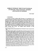
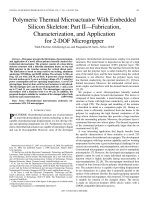
Fig. 1. (a) Schematic drawing of the silicon-polymer laterally stacked forward
actuator. The vertically constrained polymer layers expand laterally when
they receive heat transferred from the heater through the silicon meandering
structure. (b) Heat transfer path (red line) and direction of expansion of the
laterally constrained polymer layers.
3 µm wide, 60 µm long, and 30 µm deep. The other parameters
are shown in Table I. The ratios between the width of the polymer layer and the length and height of its bonded surface are 20
and 10, respectively. These values, which are larger or equal to
ten, do satisfy the prerequisite for the maximum constrain effect
[4]–[6]. According to the modeling, the expected displacement
of this forward actuator is 8.1 µm for an applied voltage of
2.5 V, with a corresponding maximum and average temperature
change on the actuator of 425 ◦ C and 310 ◦ C, respectively.
III. F ABRICATION
Fig. 2. Geometric parameters of the forward actuator.
II. D ESIGN
The specific configuration of the device is based on the
modeling results presented in [4]. A schematic drawing of the
silicon-polymer electrothermal forward actuator is shown in
Fig. 1(a). The device is based on a three-material composite.
An aluminum metal heater is deposited and patterned on top of
the silicon skeleton structure. The silicon part forms the frame
structure and acts as a heat-conducting environment due to its
high thermal conductivity. The polymer, which is an SU8 type,
is embedded between the silicon parallel plates.
When a current is applied to the heater, the generated heat
is efficiently transferred to the surrounding polymer through
the deep meandering silicon structure that has a large interface
with the polymer [see Fig. 1(b)]. The polymer layers expand
along the lateral direction due to the constraint effect [4]–[6],
causing forward displacement of the actuator. The actuation
requires low driving voltage, power consumption, and operating
temperature.
In Fig. 2, the geometry of the actuator is shown. The actuator
is 360 µm long, 125 µm wide, and 30 µm thick. It consists of
two symmetrical silicon-polymer stacks. There are 40 vertical
polymer layers in a stack. Each polymer and silicon platelike is
The silicon-polymer laterally stacked electrothermal forward
actuator is fabricated by using a three-mask process. The
process flow is schematically shown in Fig. 3.
The actuators are fabricated by using 100-mm-diameter
527-µm-thick SOI wafers (p-type, 100 orientation), with a
400-nm-thick silicon buried oxide layer and a 30-µm-thick
p-type top silicon layer. A 300-nm-thick low-pressure chemical
vapor deposition silicon nitride is deposited on both sides of the
wafer. It serves as an electrical insulator on the front and on the
backside as a mask during silicon substrate etching in KOH [see
Fig. 3(a)]. A 600-nm-thick aluminum layer is deposited and
patterned [Fig. 3(b)] to form the heater. The top silicon layer
is subsequently etched by deep reactive ion etching (DRIE) to
define the silicon frame [Fig. 3(c)]. Due to the characteristics
of the DRIE, the etch rate is faster in larger windows than in
smaller ones. Therefore, the use of SOI wafers is preferred as it
guarantees (depth) uniformity of all etched structures.
As a polymer, we have considered the NANO SU8
2000 (Microchem, Inc.), which is a high contrast, negative,
and epoxy-based line of conventional near-ultraviolet (350–
400 nm) radiation sensitivity photoresist with suitable chemical
and mechanical properties [9]. SU8 allows the fabrication of
structures with high aspect ratios and straight sidewalls [10].
It is a photopatternable polymer with a large coefficient of
thermal expansion (52–150 ppm/◦ C) [11], [12]. SU8 is a soft
material compared with other conventional materials used in
microtechnology. The Young’s modulus of elasticity ranges
from 3.2 to 4.4 GPa [11], [12], which is about 40 times softer
than silicon [13]. The negative photosensitive SU8-2002 with
a viscosity of 7.5 cSt is specifically developed to produce thin
(2–3 µm) films [14]. This polymer proved to be suitable for
filling the 3-µm-wide trenches present in our silicon-polymer
electrothermal in-plane actuator.
CHU DUC et al.: POLYMERIC THERMAL MICROACTUATOR WITH EMBEDDED SILICON SKELETON II
Fig. 3.
825
Schematic view of the silicon-polymer laterally stacked microactuator fabrication process.
Fig. 4. Experimental procedure for soft bake and postbake of the SU8-2002
polymer.
The physical properties of SU8, like most polymers, are
largely dependent on the type of structure to be realized and
the fabrication process employed. In order to get a uniform
and void-free filling of the narrow trenches, a modified coating
and a carefully determined baking process are developed.
First, the wafer is treated in Hexamethyldisilazane (HDMS)
for 5 min to improve the wetting behavior of the polymer. Then,
a sufficient amount of SU8 2002 polymer to cover the entire
wafer surface is applied on the substrate, and after waiting for
5 min to allow the polymer to sink into the trenches, the wafer
is spun at 300 r/min for 30 s. The samples are then soft-baked
on a hot plate. The hot plate is ramped with a constant rate
of 240 ◦ C/h from room temperature to 65 ◦ C and 95 ◦ C and
then cooled at a constant rate to room temperature (60 min), as
shown in Fig. 4(a).
Once the edge bead has been removed, the exposure is done
by using a wavelength of 350 nm for 60 s in an EV240 contact
aligner (EV Group Inc.). Postbake is performed after exposure
on the same hot plate used for the soft bake, following the procedure shown in Fig. 4(b). The postbake procedure is followed
by a relaxation step at room temperature for 30 min. The resist
is developed in SU8 developer for 10 min without mechanical
oscillation aids to prevent deformation or debonding during
Fig. 5. SEM pictures of the void-free filling SU8-2002.
development [see Fig. 3(d)]. Fig. 5 shows SEM pictures of the
void-free polymer-filled trenches.
Finally, the bulk silicon is etched from the backside in a
33-wt% KOH solution at 85 ◦ C until the buried oxide layer is
reached [see Fig. 3(e)]. The front side of the wafer is protected
during the etching in KOH by a vacuum holder. The last step is
the release of the structure by dry etching the buried oxide layer
from the backside [see Fig. 3(f)].
IV. M EASUREMENT S ETUPS
There are two methods for inducing a temperature change in
this electrothermal microactuator: applying a current through
the self-contained metal heater or using an external heat source.
In order to characterize the microactuator, a dc voltage is
applied by using an HP4155A semiconductor parameter analyzer (Agilent Technologies, Inc.). The voltage is ramped from
0 to 2.5 V. The displacement is monitored through the chargecoupled-device camera on top of the probe station.
The static displacement of the microactuator at any actuating
voltage is then obtained by enlarging the picture and comparing it with the picture of the initial position. The external
mechanical vibration causes a blur on the static picture which
826
JOURNAL OF MICROELECTROMECHANICAL SYSTEMS, VOL. 17, NO. 4, AUGUST 2008
Fig. 6. Forward actuator movement in air versus the applied voltage.
determines the inaccuracy of the measurement. This inaccuracy
is about ±1.5 µm.
In addition, the thermal characteristic of the microactuator is also investigated by using the built-in external heat
source of the Cascade probe station (Cascade Microtech, Inc.).
The investigated temperature range is from 20 ◦ C to 200 ◦ C
(the highest temperature of this measurement system) with a
20-◦ C step and an accuracy of ±0.1◦ C. In order to get a stable
temperature on the device, the measurement is performed 5 min
after the chuck temperature has reached the setting point to
allow sufficient stabilization. This externally supplied thermal
energy causes expansion in the constrained polymer layer and
the resulting actuation.
V. E XPERIMENTAL R ESULTS
Fig. 6 shows the forward actuator movement versus the
applied voltage. A movement up to 9.5 µm at 2.5 V is measured.
The measured results meet the simulated one within about 8%
(see Table II).
Table II indicates the simulated and measured results of the
in-plane forward actuator.
The average working temperature of the forward actuator
can be estimated by monitoring the resistance change of the
aluminum heater. The average increase in temperature of the
forward actuator is given by
∆T = T − T0 =
RT − RT0 1
RT0
λAl
(1)
where T0 is the room temperature (20 ◦ C), λAl = 4.13 × 10⁻³
[15] is the temperature coefficient of resistance of the aluminum
film, and RT0 = 88 Ω and RT are the resistances of the
aluminum heater at room temperature and at the investigated
points, respectively.
Fig. 7 shows the measured resistance of the heater in air.
The maximum resistance change for the full range of applied
voltage is 103%. The average working temperature of the forward actuator can be calculated from the resistance change by
using (1). The average temperature change is 250 ◦ C when the
applied voltage is 2.5 V. The maximum working temperature on
the actuator can be estimated to be about 356 ◦ C, considering
the simulated and measured average temperatures reported in
Table II and in [4]. The measured temperature results meet
the simulated ones within about 19%. The difference could be
explained as due to the different heat conduction and convection
conditions between experiments and simulation and the assumption of the temperature-independent physical parameters
of the employed materials. Fig. 8 shows the displacement of
the forward actuator versus the average temperature change on
the actuator.
Instead of electrical activation, external heat is applied on
the wafer with the same probe station used for the electrical
actuation measurement. The static displacement of the forward
actuator is also measured under an optical microscope. The
mechanical vibration of the chuck increases when activating
the chuck temperature controller due to the heat flow under
the chuck. Therefore, the measurement error is somewhat larger
(about ±2 µm) in this case.
The displacement of the forward actuator due to the external
heat is also shown in Fig. 8. These values meet the electrical
actuation values within 5% for the average working temperature range of 20 ◦ C–200 ◦ C. It indicates that the aluminum
deposition process behaves as expected and that the average
working temperature of the actuator can be well estimated from
the resistance change of the aluminum heater.
The physical properties of the polymer material, such as
the volume coefficient of expansion, Young’s modulus, and
so on, are greatly changed in pseudosecond order at the glass
transition temperature Tg where the material properties change
from the glassy region to the rubbery plateau region [16]. The
glass transition temperature of the polymer itself varies widely
with the fabrication process, structure, and other parameters
[12], [16], [17]. Reference [12] shows that the Tg of SU8
is nearly the baking temperature when it is below 220 ◦ C
for a baking time of 20 min. However, the Tg can increase
gradually up to the “steady-state” temperature of 118 ◦ C when
the material is baked for a longer time (60 min) at a constant
temperature of 95 ◦ C. The cross point of the two linear fitted
lines of the external heat measured results for the temperature
ranges lower and higher than 120 ◦ C, respectively, shows the
transition temperature Tg of the employed SU8 polymer (see
Fig. 8). The estimated glass transition of the SU8 of 120 ◦ C
is quite close to the value of 118 ◦ C reported in [12]. It may
indicate that the proposed postbake process of this device is
sufficient to get the steady-state value of the glass transition
temperature.
More information about the glass transition temperature and
other physical characteristics of the polymer can be found in
the glass–rubber transition behavior chapter in [16].
The transition temperature Tg shows that this proposed device works on both the glassy and rubbery plateau regions.
It therefore may partly explain the nonlinear characteristic of
the displacements due to the working temperature and also the
power consumption.
The power consumption is calculated through the applied
voltage and the corresponding current. Fig. 9 shows the
CHU DUC et al.: POLYMERIC THERMAL MICROACTUATOR WITH EMBEDDED SILICON SKELETON II
827
TABLE II
PERFORMANCE OF THE ELECTROTHERMAL FORWARD ACTUATOR
Fig. 7. Resistance of the heater versus applied voltage and the resulting
average temperature change in the microactuator.
Fig. 9. Forward actuator movement versus the power consumption.
Fig. 8. Forward actuator movement in air versus the average temperature
change.
Fig. 10. Time-resolved electrical resistance of the forward actuator in air.
forward actuator movement versus the power consumption of
the forward actuator. The average power consumption is about
3.7 mW for a 1-µm movement of the forward actuator.
The response time of the presented forward actuator is
estimated from the thermal time response. The thermal time
response of the forward actuator operating in air is obtained
by investigating the time-resolved electrical measurement of
the aluminum heater (see Fig. 10). A single-step voltage of
0.25–2.5 V and 2.5–0.25 V is applied to the actuator to
characterize the heating and cooling response time, respectively. The drive voltage of 2.5 V corresponds to the maximum
displacement of the forward actuator. Fig. 10 shows the corresponding resistance due to the step input voltages. The actuators
reach a 90% of full range steady state after approximately
828
JOURNAL OF MICROELECTROMECHANICAL SYSTEMS, VOL. 17, NO. 4, AUGUST 2008
Fig. 11. 2-D microgripper based on four silicon-polymer laterally stacked in-plane forward actuators.
TABLE III
GEOMETRY OF THE ELECTROTHERMAL 2-D MICROGRIPPER
40 and 50 ms for heating and cooling, respectively. An ∼11-Hz
bandwidth frequency of this actuator is therefore calculated.
VI. T WO -D IMENSIONAL M ICROGRIPPER
A very interesting application that largely benefits from the
specific characteristics of these actuators is a novel 2-D siliconpolymer laterally stacked electrothermal microgripper.
Fig. 12. Schematic drawing of the 2-D microgripper movement mechanism.
Phase 0 is the initial position. Phase 1: Jaws are closed on the y-axis to clamp
an object. Phase 2: One jaw is moved along the x-axis to rotate the object
clockwise. Phase 3: The other jaw is moved along the x-axis to rotate the object
counterclockwise.
When voltages Vy1 and Vy2 are applied on the two y actuators, the microgripper is stretched along the y-axis (phase 2 or
3 in Fig. 12). The displacement uy is thus given by
uy =
A. Design
The design and geometry of the microgripper is shown in
Fig. 11 and Table III. The microgripper’s arm structure consists
of two perpendicular forward actuators to control the motion
along the x- and y-axes, respectively. To control this 2-D
microactuator, four input voltages are employed, as shown in
Fig. 11. The moving mechanism is shown in Fig. 12.
When voltages Vx1 and Vx2 are applied on the two x actuators, the microgripper closes along the x-axis to clamp the
object (phase 1 in Fig. 12). The displacement in the x-direction
ux of each jaw is given by
ux =
Wy1 + Wy2
d
Wy1
Wx1 + Wx2
d
Wx1
(3)
where Wx1 and Wx2 are related to the dimensions of the
actuator and the gripper arm on the x-axis.
By combining the motion in two directions, this 2-D microgripper provides the additional feature to rotate the clamped
object clockwise and counterclockwise (phases 2 and 3 in
Fig. 12) when a voltage is alternately applied on the y actuators.
An object with a radius r can be rotated of an angle (with
respect to its center) α calculated as
α=
1 uy
360◦ .
2 2πr
(4)
(2)
where Wy1 and Wy2 are related to the dimensions of the actuator and the gripper arm on the y-axis, and d is the displacement
of the forward actuator.
B. Experimental Results
Fig. 13 shows the realized silicon-polymer laterally stacked
electrothermal 2-D microgripper. The parameters related to the
CHU DUC et al.: POLYMERIC THERMAL MICROACTUATOR WITH EMBEDDED SILICON SKELETON II
829
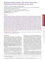
Fig. 13. SEM pictures of the fabricated 2-D microgripper. (a) Entire device. (b) Front view of the electrothermal forward actuator. (c) Microgripper jaws.
(d) Two forward actuators are connected together by using silicon comb structure filled with the SU8.
TABLE IV
PERFORMANCE OF THE ELECTROTHERMAL 2-D MICROGRIPPER
Fig. 14. Two-dimensional microgripper operation. (a) Initial position: the
distance between the two jaws is 40 µm on the x-axis. (b) The microgripper
jaws when applying 2.5 V to both y actuators. (c) One jaw moves along the
y-axis when applying 2.5 V to its y actuator.
geometry of the fabricated microgripper are reported in Tables I
and III and Figs. 2 and 11.
Fig. 14 shows images of some typical states of the 2-D
microgripper. Fig. 14(a) shows the initial position of the 2-D
microgripper jaws. The gap between the two jaws is 40 µm.
In Table IV, the simulated and measured results of the 2-D
microgripper are reported.
Fig. 15 shows the movement of a single jaw of the microgripper along the x- and y-axes versus the applied voltage. The
maximum measured movements of one jaw are 17 and 11 µm
along the x- and y-axes, respectively. Hence, this microgripper is capable of manipulating an object with a diameter of
6–40 µm. The difference between the movement of the jaw
along the x- and y-axes is related to the geometry of the design,
as indicated in (2) and (3). The maximum angle of rotation
can be estimated based on (4) and the related measured values.
For a 30-µm-diameter object, this angle is 21◦ both clockwise
and counterclockwise. The applied force on the clamped object
can be estimated through the measured displacement and the
simulated stiffness of the gripper arm. This proposed device
830
JOURNAL OF MICROELECTROMECHANICAL SYSTEMS, VOL. 17, NO. 4, AUGUST 2008
generates 80% of its maximum displacement) and a frequency
of 1.7 Hz for 12 h (70 000 Hz). The same reliability testing
process is repeated after one week and then one month. No
degradation in performance is observed so far.
VII. C ONCLUSION
Fig. 15. Microgripper jaw movement in air along the x- and y-axes versus
applied voltage.
A novel silicon-polymer electrothermal in-plane forward actuator with a large measured displacement (up to 9.5 µm) at the
applied voltage of 2.5 V was presented. A 2-D electrothermal
microgripper, which is an interesting application of the proposed forward actuator, was presented as well. Microgripper
jaw displacements up to 17 and 11 µm along the x- and
y-axes, respectively, at 2.5-V applied voltage were measured.
The microgripper can be used to grasp and rotate an object
with a diameter of 6–40 µm. For a 30-µm-diameter object,
a maximum rotation of about 21◦ both clockwise and counterclockwise can be performed. The maximum average temperature change is 250 ◦ C at 2.5 V. The proposed device
works at both the glassy and rubbery plateau regions of the
SU8 polymer. The average power consumptions are about
2.1 and 3.1 mW for a 1-µm movement along the x- and yaxes, respectively. The bandwidth frequency at the full range
displacement is calculated to be 11 Hz. The fabrication process
is based on conventional bulk micromachining and polymer
filling, and it is CMOS-compatible. The proposed microgripper
due to the demonstrated features appears to be quite suitable for
microobject manipulation, device positioning, microrobotics,
and microassembly.
ACKNOWLEDGMENT
Fig. 16. Microgripper jaw movement in air along the x- and y-axes versus
power consumption.
The authors would like to thank the DIMES-IC Processing Group for the technical support and P. J. F. Swart for
his assistance with the electronic measurements. The authors would also like to thank J. Wei, Dr. H. W. van Zeijl,
Dr. J. F. Creemer, Dr. J. F. L. Goosen, and F. van Keulen for the
numerous discussions.
R EFERENCES
is capable of generating a maximum applied force of 196 and
814 µN on the x- and y-axes, respectively (see Table IV).
Fig. 16 shows the microgripper jaw displacement along
the x- and y-axes versus the power consumption. For 1-µm
microgripper jaw movement along the x- and y-axes, about
2.1 and 3.1 mW are consumed, respectively. The difference is
due to the geometry of the gripper jaws (see Fig. 11) and is
expressed in (2) and (3). The main failure mechanism observed
during testing the microgripper is the appearance of cracks
in the aluminum heater and the silicon meandering structure
when the applied voltage is increased to about 3 V and the
working temperature of the actuator is too high. There is no
indication of loss of adhesion between the SU8 and the silicon
plates even at these temperatures. This is probably due to the
large interface between the meandering silicon structure and
the polymer. To evaluate the lifetime of the microgripper, it
is repeatedly actuated in air with a 2-V amplitude (which
[1] N. Chronis and L. P. Lee, “Electrothermally activated SU-8 microgripper for single cell manipulation in solution,” J. Microelectromech. Syst.,
vol. 14, no. 4, pp. 857–863, Aug. 2005.
[2] N.-T. Nguyen, S.-S. Ho, and C. L.-N. Low, “A polymeric microgripper
with integrated thermal actuators,” J. Micromech. Microeng., vol. 14,
no. 7, pp. 969–974, May 2004.
[3] J. W. L. Zhou, H.-Y. Chan, T. K. H. To, K. W. C. Lai, and W. J. Li, “Polymer MEMS actuators for underwater micromanipulation,” IEEE/ASME
Trans. Mechatronics, vol. 9, no. 2, pp. 334–342, Jun. 2004.
[4] G.-K. Lau, J. F. L. Goosen, F. van Keulen, T. Chu Duc, and
P. M. Sarro, “Polymeric thermal microactuator with embedded silicon skeleton: Part I—Design and analysis,” J. Microelectromech. Syst.,
vol. 17, no. 4, pp. 809–822, Aug. 2008.
[5] T. Chu Duc, G. K. Lau, J. Wei, and P. M. Sarro, “2D electro-thermal
microgrippers with large clamping and rotation motion at low driving
voltage,” in Proc. 20th IEEE Conf. MEMS, 2007, pp. 687–690.
[6] T. Chu Duc, G. K. Lau, and P. M. Sarro, “Polymer constraint effect for
electrothermal bimorph microactuators,” Appl. Phys. Lett., vol. 91, no. 10,
pp. 101 902-1–101 902-3, Sep. 2007.
[7] P. K. Wong, U. Ulmanella, and C.-M. Ho, “Fabrication process of
microsurgical tools for single-cell trapping and intracytoplasmic injection,” J. Microelectromech. Syst., vol. 13, no. 6, pp. 940–946,
Dec. 2004.
CHU DUC et al.: POLYMERIC THERMAL MICROACTUATOR WITH EMBEDDED SILICON SKELETON II
[8] M. Mita, H. Kawara, H. Toshiyoshi, M. Ataka, and H. Fujita, “An electrostatic 2-dimensional micro-gripper for nano structure,” in Proc. 12th
IEEE Int. Conf. Solid-State Sens., Actuators, Microsyst., Jun. 8–12, 2003,
pp. 272–275.
[9] A. Mata, A. J. Fleischman, and S. Roy, “Fabrication of multi-layer SU-8
microstructures,” J. Micromech. Microeng., vol. 16, no. 2, pp. 276–284,
Jan. 2006.
[10] J. D. Williams and W. Wang, “Study on the postbaking process and
the effects on UV lithography of high aspect ratio SU-8 microstructures,” J. Microlithogr. Microfabr. Microsyst., vol. 3, no. 4, pp. 563–568,
Oct. 2004.
[11] H. Lorenz, M. Laudon, and P. Renaud, “Mechanical characterization
of a new high-aspect-ratio near UV-photoresist,” Microelectron. Eng.,
vol. 41/42, pp. 371–374, Mar. 1998.
[12] R. Feng and R. J. Farris, “Influence of processing conditions on the
thermal and mechanical properties of SU8 negative photoresist coatings,”
J. Micromech. Microeng., vol. 13, no. 1, pp. 80–88, Dec. 2003.
[13] J. J. Wortman and R. A. Evans, “Young’s modulus, shear modulus, and
Poisson’s ratio in silicon and germanium,” J. Appl. Phys., vol. 36, no. 1,
pp. 153–156, Jan. 1965.
[14] NANO SU-8 2000 Negative Tone Photoresist Formulations 2002–2025,
MicroChem Corp., Newton, MA, 2002.
[15] Handbook of Thermophysical Properties of Metals at High Temperatures,
Nova, Commack, NY, 1996, pp. 139–144.
[16] L. H. Sperling, Introduction to Physical Polymer Science. Hoboken, NJ:
Wiley, 2006.
[17] J. H. van Zanten, W. E. Wallace, and W. Wu, “Effect of strongly favorable substrate interactions on the thermal properties of ultrathin polymer
films,” Phys. Rev. E, Stat. Phys. Plasmas Fluids Relat. Interdiscip. Top.,
vol. 53, no. 3, pp. R2053–R2056, Mar. 1996.
Trinh Chu Duc received the B.S. degree in physics
from Hanoi University of Science, Hanoi, Vietnam,
in 1998, the M.Sc. degree in electrical engineering
from Vietnam National University, Hanoi, in 2002,
and the Ph.D. degree from Delft University of Technology, Delft, The Netherlands, in 2007. His Ph.D.
research topics are piezoresistive sensors, polymeric
actuators, sensing microgripper for microparticle
handling, and microsystems technology.
He is currently an Assistant Professor with the
Faculty of Electronics and Telecommunication, College of Technology, Vietnam National University.
831
Gih-Keong Lau received the bachelor’s (with firstclass honors) and master’s degrees in mechanical
engineering from Nanyang Technological University (NTU), Singapore, in 1998 and 2001, respectively, and the Ph.D. degree from Delft University
of Technology, Delft, The Netherlands, in 2007.
His Ph.D. research topics were polymeric actuators,
electroactive polymer, microfabrication, and multiphysics modeling and design.
From 2001 to 2003, he was a Research Associate
with the Center for Mechanics of Microsystems,
NTU, working on the topics of topology optimization of compliant mechanisms, mechanical design for hard disk drives, and piezoelectric actuators. He is
currently an Assistant Professor with the School of Mechanical and Aerospace
Engineering, NTU.
Pasqualina M. Sarro (M’84–SM’97–F’07) received
the Laurea degree (cum laude) in solid-state physics
from the University of Naples, Naples, Italy, in 1980
and the Ph.D. degree in electrical engineering from
Delft University of Technology, Delft, The Netherlands, in 1987. Her Ph.D. dissertation dealt with
infrared sensors based on integrated silicon thermopiles.
From 1981 to 1983, she was a Postdoctoral Fellow with the Photovoltaic Research Group, Division
of Engineering, Brown University, RI, where she
worked on thin-film photovoltaic cell fabrication by chemical spray pyrolysis. Since then, she has been with the Delft Institute of Microelectronics
and Submicron Technology (DIMES), Delft University of Technology, where
she is responsible for the research on integrated silicon sensors and MEMS
technology. In April 1996, she became an Associate Professor, and in December
2001 a Full Professor, in the Electronic Components, Materials and Technology
Laboratory, Delft Institute of Microsystems and Nanoelectronics, Delft University of Technology. She has authored and coauthored more than 300 journal and
conference papers.
Dr. Sarro received the EUROSENSORS Fellow Award for her contribution
to the field of sensor technology in 2004. She has served as a Member of the
Technical Program Committees of the European Solid-State Device Research
Conference (since 1995), the EUROSENSORS Conference (since 1999), and
the IEEE International Conference on Micro Electro Mechanical Systems (2006
and 2007). Further, she was Technical Program Cochair for the First IEEE
Sensors Conference (2002) and the Technical Program Chair for the Second
and Third IEEE Sensors Conference (2003 and 2004). She is also a member of
the AdCom of the IEEE Sensor Council.