DSpace at VNU: Nonlinear thermal stability of eccentrically stiffened functionally graded truncated conical shells surrounded on elastic foundations
Bạn đang xem bản rút gọn của tài liệu. Xem và tải ngay bản đầy đủ của tài liệu tại đây (514.18 KB, 37 trang )
Accepted Manuscript
Nonlinear thermal stability of eccentrically stiffened functionally graded truncated
conical shells surrounded on elastic foundations
Nguyen Dinh Duc , Pham Hong Cong
PII:
S0997-7538(14)00167-3
DOI:
10.1016/j.euromechsol.2014.11.006
Reference:
EJMSOL 3141
To appear in:
European Journal of Mechanics / A Solids
Received Date: 28 February 2014
Revised Date:
1 November 2014
Accepted Date: 7 November 2014
Please cite this article as: Duc, N.D., Cong, P.H., Nonlinear thermal stability of eccentrically stiffened
functionally graded truncated conical shells surrounded on elastic foundations, European Journal of
Mechanics / A Solids (2014), doi: 10.1016/j.euromechsol.2014.11.006.
This is a PDF file of an unedited manuscript that has been accepted for publication. As a service to
our customers we are providing this early version of the manuscript. The manuscript will undergo
copyediting, typesetting, and review of the resulting proof before it is published in its final form. Please
note that during the production process errors may be discovered which could affect the content, and all
legal disclaimers that apply to the journal pertain.
ACCEPTED MANUSCRIPT
Nonlinear thermal stability of eccentrically stiffened functionally graded
truncated conical shells surrounded on elastic foundations
Nguyen Dinh Duc*, Pham Hong Cong
Vietnam National University, Hanoi -144 Xuan Thuy-Cau Giay- Hanoi-Vietnam
RI
PT
Abstract
This paper studies the thermal stability of an eccentrically stiffened functionally graded
truncated conical shells in thermal environment and surrounded on elastic foundations. Both
of the FGM shell as well as the stiffeners are deformed under temperature. The formulations
SC
are based on the classical shell theory taking into account geometrical nonlinearity, initial
geometrical imperfection, temperature-dependent properties and the Lekhnitsky smeared
stiffeners technique with Pasternak type elastic foundation. By applying Galerkin method, the
M
AN
U
closed-form expression for determining the thermal buckling load is obtained. The numerical
results show that the critical thermal load in the case of the uniform temperature rise is
smaller than one of the linear temperature distribution through the thickness of the shell, and
the critical thermal load increases when increasing the coefficient of stiffeners and vice versa.
The paper also analyzes and discussed the significant effects of material and geometrical
TE
D
properties, elastic foundations on the thermal buckling capacity of the eccentrically stiffened
FGM truncated conical shell in thermal environment. The obtained results are validated by
comparing with those in the literature.
Keywords: Thermal stability, Eccentrically stiffened truncated conical shell, Functionally
1. Introduction
EP
graded materials, elastic foundations.
AC
C
The idea of the construction of functionally graded meterials (FGM) was first
introduced in 1984 by a group of Japanese materials scientists (Koizumi, 1997).
Due to high performance heat resistance capacity and excellent characteristics of
FGM in comparison with conventional composites, functionally graded shells
involving conical shells are widely used in exhaust nozzle of solid rocket engine,
some important details of space vehicles, aircrafts, nuclear power plants and many
other engineering applications. As a results stability analysis of those strutures are
very important problems and have attracted increasing research effort.
1
ACCEPTED MANUSCRIPT
The static stability of conical shells has been studied by many researchers in the
recent years. However, most of them have focused on buckling behaviors and
determining the critical loads for the shells without elastic foundations and stiffeners:
The buckling of conical shells under the axial compression (Seide 1956, 1961), the
thermal buckling of concial shells (Lu and Chang, 1967), solution of buckling for
RI
PT
truncated conical shells under combined pressure and heating (Tani, 1984), the
thermoelastic buckling of laminated composite conical shells (Wu and Chiu, 2001),
thermal and mechanical instability of truncated conical shells made of FGM (Naj et al.
2008), an analytical approach to investigate the linear buckling of truncated conical
SC
panels made of FGM and subjected to axial compression, external pressure and the
combination of these loads (Bich et al, 2012), the thermoelastic stability of
M
AN
U
functionally graded truncated conical shells (Sofiyev, 2007), the buckling of thin
truncated conical shells made of FGMs subjected to hydrostatic pressure, uniform
external pressure and uniform axial compressive load (Sofiyev et al. 2004, 2009,
2010a). The shell structures supported by an elastic foundations have been widely
used in many applications such as in aircraft, reusable space transportation vehicles
TE
D
and civil engineering. Therefore, studies on the effects of elastic foundations on
behavior and loading capacity of the shells are highly important. The nonlinear
buckling of the truncated conical shell made of FGMs was surrounded by an elastic
medium and Winkler–Pasternak type elastic foundation using the large deformation
EP
theory with von Karman–Donnell-type of kinematic nonlinearity (Sofiyev, 2010b;
Sofiyev and Kuruoglu, 2013). Najafov and Sofiyev (2013) obtained the nonlinear
AC
C
dynamic analysis of FG truncated conical shells surrounded by an elastic medium
using the large deformation theory with von Karman–Donnell-type of kinematic nonlinearity.
Pratically, the composite plates and shells usually are reinforced by stiffening
components to provide the benefits of added load-carrying static and dynamic
capability with a relatively small additional weight. There have had some publications
on the buckling of composite shells reinforced by stiffeneres: a free vibration analysis
for a ring-stiffened simply supported conical shell by considering an equivalent
2
ACCEPTED MANUSCRIPT
orthotropic shell and using Galerkin method and carried out experimental
investigations (Weingarten, 1965), an energy approach to find the resonant
frequencies of simply supported ring-stiffened, and ring and stringer-stiffened conical
shells (Crenwelge and Muster, 1969), the nonlinear static buckling and post-buckling
for imperfect eccentrically stiffened functionally graded thin circular cylindrical shells
RI
PT
surrounded on elastic foundation (Duc and Thang, 2014), a semi-analytical approach
to investigate the nonlinear dynamic of imperfect eccentrically stiffened FG shallow
shells taking into account the damping subjected to mechanical loads (Bich et al.,
2013), the study of instability of eccentrically stiffened functionally graded truncated
SC
conical shells under mechanical loads and shells are reinforced by stringers and rings
(Dung et al. 2013), the stability of functionally graded truncated conical shells
M
AN
U
reinforced by functionally graded stiffeners, surrounded by an elastic medium and
under mechanical loads (Dung et al., 2014).
From the above review, to the best of our knowledge, it has showed that there is
no publiation about buckling of FGM conical shell with stiffeneres in thermal
environment. Under temperature, both of the FGM shell as well as the stiffeners are
TE
D
deformed, therefore, the calculation on the thermal mechanism of FGM shells and
stiffeners has become more difficult. Recently, Duc and Quan (2013) researched the
nonlinear postbuckling for imperfect eccentrically stiffened FGM double curved thin
shallow shells on elastic foundation using a simple power-law distribution in thermal
EP
environments. Duc and Cong (2014) also investigated the nonlinear postbuckling of
AC
C
imperfect eccentrically stiffened thin FGM plates under temperature.
This paper studied the stability of an eccentrically stiffened functionally graded
truncated conical shells surrounded on elastic foundations under thermal loads with
both FGM shell and stiffeners having temperature-dependent properties. Addionally,
the paper analyzed and discussed the effects of material and geometrical properties,
temperature, elastic foundations and eccentrically stiffeners on the buckling and
postbuckling loading capacity of the functionally graded truncated conical shells in
thermal environments.
3
ACCEPTED MANUSCRIPT
2. Eccentrically stiffened functionally graded (ES-FGM) truncated conical shell
surrounded on elastic foundations
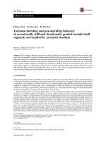
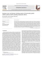
Consider a thin truncated conical shell of thickness h and semi-vertex angle
β , the geometry of shell is shown in Fig. 1, in which L is the length, R1 is its small
RI
PT
base radius and R, H geometrical parameters as shown in Fig. 1. The truncated cone
is referred to a curvilinear coordinate system ( x,θ , z ) whose the origin is located in
the middle surface of the shell, x is in the generatrix direction measured from the
vertex of conical shell, h is in the circumferential direction and the axes z being
SC
perpendicular to the plane ( x, h ) , lies in the outwards normal direction of the cone.
Also, x0 indicates the distance from the vertex to small base, and u , v and w denote
M
AN
U
the displacement components of a point in the middle surface in the direction x, h and
z , respectively; h1 and b1 are the thickness and width of stringer ( x -direction); h2
and b2 are the thickness and width of ring ( θ -direction). Also, d1 = d1 ( x ) and d 2 are
the distance between two stringers and two rings, respectively. z1 , z2 represent the
TE
D
eccentricities of stiffeners with respect to the middle surface of shell.
The effective properties of the FGM truncated conical shell (the elastic
modulus E , the Poisson ratioν , the thermal expansion coefficient α ) can be written as
2014):
EP
follows (Bich et al., 2011; Dung et al., 2013; Duc and Quan, 2013; Duc and Cong,
2z + h
( E ,α ) = ( Em ,α m ) + ( Ecm ,α cm )
,
2h
N
AC
C
(1)
where Ecm = Ec − Em , α cm = α c − α m , the volume fraction index N is a nonnegative
number that defines the material distribution and can be chosen to optimize the
structural response, and subscripts m and c stand for the metal and ceramic
constituents, respectively. And the Poisson ratio is assumed to be constant ν = const .
From Eq. (1) we have: E = Em at z = −h / 2 (metal-rich) and E = Ec at z = h / 2
(ceramic-rich).
4
ACCEPTED MANUSCRIPT
β
RI
PT
β
M
AN
U
SC
θ
x0 = R1 sin β , H = L cos β , R = R1 +
L
sin β
2
TE
D
Fig. 1. Eccentrically stiffened FGM truncated conical shell surrounded by an elastic
foundations.
A material property Pr of both FGM truncated conical shell and stiffeners, such
EP
as the elastic modulus E , the Poisson ratioν , the thermal expansion coefficient α can
be expressed as a nonlinear function of temperature (Touloukian, 1967):
−1
3
Pr = P0 ( P−1T −1 + 1 + PT
+ P2T 2 + PT
),
1
3
AC
C
(2)
in which T = T0 + ∆T ( z ) and T0 = 300 K (room temperature); P−1 , P0 , P1 , P2 , P3 are
coefficients characterizing of the constituent materials. ∆T is temperature rise from
stress free initial state, and more generally, ∆T = ∆T ( z ) . In short, we will use T-D
(temperature dependent) for the cases in which the material properties depend on
temperature. Otherwise, we use T-ID for the temperature independent cases. The
material properties for the later one have been determined by Eq. (2) at room
temperature, i.e. T0 = 300 K .
5
ACCEPTED MANUSCRIPT
The FGM truncated conical shell is surrounded by an elastic foundations (Fig.
1). Pasternak model is used to describe the reaction of the elastic foundations on the
conical shell. If the effects of damping and inertia force in the foundations are
neglected, the foundation interface pressure (Sofiyev, 2013; Najafov, 2013):
q ( x,θ ) = K1w − K 2 ∆w,
∂ 2 w 1 ∂w
1
∂2w
+
+
, K1 (in N / m3 ) is the Winkler foundation
2
2
2
2
∂x
x ∂x x sin α ∂θ
RI
PT
where ∆w =
(3)
stiffeness and K 2 (in N / m ) is the shear subgrade modulus of the Pasternak
SC
foundation model.
3. Eccentrically stiffened FGM truncated conical shell under temperature
M
AN
U
The present study uses the classical shell theory with the geometrical
nonlinearity in von Karman sense and smeared stiffeners technique to establish the
governing equations. Thus, the normal and shear strains at distance z from the middle
surface of shell are (Brush and Almroth, 1975):
ε x = ε x0 + zk x , εθ = εθ0 + zkθ , γ xθ = γ x0θ + 2 zk xθ ,
(4)
TE
D
in which ε x0 and ε θ0 are the normal strains and γ x0θ is the shear strain at the middle
surface of the shell, and k x , kθ and k xθ are the change of curvatures and twist,
respectively. They are related to the displacement components as (Brush and Almroth,
EP
1975):
∂u 1 ∂w
ε = + ,
∂x 2 ∂x
2
AC
C
0
x
1 ∂v u w
1
∂w
εθ =
+ + cot β + 2 2
,
x sin β ∂θ x x
2 x sin β ∂θ
1 ∂u v ∂v
1 ∂w ∂w
γ x0θ =
− + +
,
x sin β ∂θ x ∂x x sin β ∂x ∂θ
0
kx = −
2
(5)
∂2w
1
∂ 2 w 1 ∂w
,
k
=
−
−
,
θ
∂x 2
x 2 sin 2 β ∂θ 2 x ∂x
1
∂ 2w
1
∂w
k xθ = −
+ 2
.
x sin β ∂x∂θ x sin β ∂θ
Hooke law for an FGM truncated conical shell with temperature-dependent
6
ACCEPTED MANUSCRIPT
properties is defined as
E
ε x + vε θ − (1 + v ) α∆T ( z ) ,
1 − v2
E
=
ε θ + vε x − (1 + v ) α∆T ( z ) ,
1 − v2
E
γ xθ .
=
2 (1 + v )
σ xsh =
σ xshθ
(6)
RI
PT
σ θsh
For stiffeners in thermal environments, we have proposed its form adapted from
(Duc and Quan, 2013; Duc and Cong, 2014) as the follows:
Est
α st ∆T ( z ) ,
1 − 2vst
Er
σ θ = Er εθ −
α r ∆T ( z ) ,
1 − 2vr
SC
σ xs = Est ε x −
(7)
M
AN
U
s
here, Est = Est (T ) , vst = vst (T ) , α st = α st ( T ) are the Young’s modulus, Poisson ratio
and thermal expantion coefficient of the stiffener in the x -direction, respectively. And
Er = Er (T ) , vr = vr (T ) ,α r = α r (T ) are the Young’s modulus, Poisson ratio and
thermal expantion coefficient of the stiffener in the θ -direction, respectively. To
TE
D
guarantee the continuity between the stiffener and shell, the stiffener is taken to be
pure-metal if it is located at metal-rich side and is pure-ceramic if it is located at
ceramic-rich side (this assumption was proposed by Bich in (Bich et al., 2011)). In
EP
order to investigate the FGM truncated conical shell with stiffeners in thermal
environment, we have not only taken into account the materials muduli with
AC
C
temperature-dependent properties but also assumed that all elastic moduli of FGM
truncated conical shell and stiffener are temperature dependence and they are
deformed in the presence of temperature. Hence, the geometric parameters, the shell’s
shape and stiffeners are varied through the deforming process due to the temperature
change. We have assumed that the thermal stress of stiffeners is subtle which
distributes uniformly through the whole shell structure, therefore, we can ignore it
because the size of stiffeners is great smaller than the plates and the gap between
every stiffeners is not tight (this assumption first was proposed by Duc et al. (2013)
and has been used in Duc and Cong (2014)).
7
ACCEPTED MANUSCRIPT
Taking into account the contribution of stiffeners by the smeared stiffener
technique and omitting the twist of stiffeners because of these torsion constants are
smaller than the moments of inertia (Brush and Almroth, 1975). In addition, the
change of spacing between stringers in the meridional direction is also taken into
account. Integrating the above stress–strain equations and their moments through the
RI
PT
thickness of the shell, we obtain the expressions for force and moment resultants of an
eccentrically stiffened FGM conical shells (Dung et al., 2013, 2014).
N xθ = A66γ x0θ + 2 B66 k xθ ,
M
AN
U
SC
Est A1T 0
0
N x = A11 +
ε x + A12ε θ + B11 + C1 ( x ) k x + B12 kθ + Φ a ,
d1 ( x )
Er A2T 0
0
Nθ = A12ε x + A22 +
ε θ + B12 k x + [ B22 + C2 ] kθ + Φ a ,
d2
Est I1T
M x = B11 + C1 ( x ) ε + B12ε θ + D11 +
k x + D12 kθ + Φ b ,
d1 ( x )
E IT
M θ = B12ε x0 + [ B22 + C2 ] ε θ0 + D12 k x + D22 + r 2 kθ + Φ b ,
d2
M xθ = B66γ x0θ + 2 D66 k xθ ,
AC
C
EP
in which
0
TE
D
0
x
8
(8a)
(8b)
ACCEPTED MANUSCRIPT
E1 = E m h +
E3 =
E cm h
1
1
, E 2 = E cm h 2
−
,
N +1
N + 2 2N + 2
1
1
1
1
E m h 3 + E cm h 3
−
+
,
12
N + 3 N + 2 4N + 4
h T + h1T T h T + h2T
, z2 =
,
2
2
E AT z T
L
2π sin β
C 2 = ± r 2T 2 , d1 ( x ) = λ0 x , d 2 = , λ0 =
,
d2
nr
n st
C1 ( x ) =
C10 0
E AT z T
, C1 = ± st 1 1 ,
x
λ0
E ( z )α ( z )
∫ 1 − v ∆ T ( z ) dz ,
− h/2
Φa = −
E ( z )α ( z )
∆ T ( z ) zdz ,
1− v
− h/2
SC
h/2
∫
(9)
M
AN
U
h/2
Φb = −
RI
PT
A1T = b1T h1T , A2T = b2T h2T , z1T =
2
2
1 T T 3
1 T T 3
b1 ( h1 ) + A1T ( z1T ) , I 2T =
b2 ( h2 ) + A2T ( z 2T ) ,
12
12
E1
vE1
E1
A11 = A22 =
, A12 =
, A66 =
,
2
2
1− v
1− v
2 (1 + v )
I1T =
E2
vE 2
E2
, B12 =
, B66 =
,
2
2
1− v
1− v
2 (1 + v )
D11 = D22 =
E3
vE 3
E3
, D12 =
, D66 =
,
2
2
1− v
1− v
2 (1 + v )
TE
D
B11 = B22 =
EP
After the thermal deformation process, the geometric shapes of stiffeners can be
determined as follows:
h1T = h1 (1 + α 0 ∆T ( z ) ) , h2T = h2 (1 + α 0 ∆T ( z ) ) ,
AC
C
z1T = z1 (1 + α 0 ∆T ( z ) ) , z2T = z2 (1 + α 0 ∆T ( z ) ) ,
b1T = b1 (1 + α 0 ∆T ( z ) ) , b2T = b2 (1 + α 0 ∆T ( z ) ) ,
(10)
d1T = d1 (1 + α 0 ∆T ( z ) ) , d 2T = d 2 (1 + α 0 ∆T ( z ) ) ,
in which α 0 is thermal expantion coefficient of the stiffener; nst , nr are the number of
stringer and ring respectively. The quantities A1 , A2 are the cross-section areas of
stiffeners and I1 , I 2 are the second moments of inertia of the stiffener cross sections
related to the shell middle surface. Although the stiffeners are deformed by
9
ACCEPTED MANUSCRIPT
temperature, we have assumed that the stiffeners keep its rectangular shape of the
cross section. Therefore, it is straight forward to calculate A1T , A2T .
The nonlinear equilibrium equations of truncated conical shells surronded by
elastic foundations based on the classical shell theory are given by (Brush and
Almroth, 1975):
∂N x
1 ∂N xθ
+
+ N x − Nθ = 0,
∂x sin α ∂θ
RI
PT
x
(11a)
∂N
1 ∂Nθ
+ x xθ + 2 N xθ = 0,
sin α ∂θ
∂x
(11b)
SC
2 ∂ 2 M xθ 1 ∂M xθ
∂2M x
∂M x
2
+
+
+
+
sin α ∂x∂θ
x ∂θ
∂x 2
∂x
1
1
∂ 2 M θ ∂M θ
∂w
∂w
−
−
N
cot
+
xN
+
N
α
x
x
θ
θ
+
x sin 2 α ∂θ 2
∂x
∂x sin α
∂θ , x
M
AN
U
x
(11c)
1
∂w
1
∂w
+
Nθ
N xθ
− xK1w + xK 2 ∆w = 0,
sin α
∂x x sin α
∂θ ,θ
The stability equations of conical shell are derived using the adjacent
TE
D
equilibrium criterion (Brush and Almroth, 1975; Naj et al., 2008). Assume that the
equilibrium state of ES-FGM conical shell under thermal loads is defined in terms of
the displacement components u0 , v0 and w0 . We give an arbitrarily small increments
u1 , v1 and w1 to the displacement variables, so the total displacement components of a
EP
neighboring state are:
u = u0 + u1 , v = v0 + v1 , w = w0 + w1.
(12)
AC
C
Similarly, the force and moment resultants of a neighboring state may be related
to the state of equilibrium as:
N x = N x 0 + N x1 , Nθ = Nθ 0 + Nθ 1 , N xθ = N xθ 0 + N xθ 1 ,
M x = M x 0 + M x1 , M θ = M θ 0 + M θ 1 , M xθ = M xθ 0 + M xθ 1 ,
(13)
where terms with 0 subscripts correspond to the u0 , v0 , w0 displacements and those
with 1 subscripts represents the portions of increments of force and moment resultants
that are linear in u1 , v1 and w1 . The stability equations may be obtained by substituting
Eqs. (12) and (13) into Eqs. (11) and note that the terms in the resulting equations with
10
ACCEPTED MANUSCRIPT
subscript 0 statisfy the equilibrium equations and therefore drop out of the equations.
In addition, the nonlinear terms with subscript 1 are ignored because they are small
compared to the linear terms. The remaining terms form the stability equations as
follows (Dung et al., 2014) :
∂N x1
1 ∂N xθ 1
+
+ N x1 − Nθ 1 = 0,
∂x
sin α ∂θ
(14a)
RI
PT
x
∂N
1 ∂Nθ 1
+ x xθ 1 + 2 N xθ 1 = 0,
sin α ∂θ
∂x
(14b)
SC
∂ 2 M x1
∂M x1
2 ∂ 2 M xθ 1 1 ∂M xθ 1
x
+2
+
+
+
∂x 2
∂x
sin α ∂x∂θ
x ∂θ
1
1
∂ 2 M θ 1 ∂M θ 1
∂w1
∂w1
−
− Nθ 1 cot α + xN x 0
+
N xθ 0
+
2
2
x sin α ∂θ
∂x
∂x sin α
∂θ , x
(14c)
M
AN
U
1
1
∂w1
∂w1
+
Nθ 0
N xθ 0
− xK1w + xK 2 ∆w = 0.
sin α
∂x x sin α
∂θ ,θ
where the force and moment resultants for the state of stability are given by (Naj et al.,
2008):
TE
D
E AT
C0
N x1 = A11 + st 1 ε x01 + A12ε θ01 + B11 + 1 k x1 + B12 kθ 1 ,
λ0 x
x
EP
E AT
Nθ 1 = A12ε x01 + A22 + r 2 ε θ01 + B12 k x1 + [ B22 + C2 ] kθ 1 ,
d2
N xθ 1 = A66γ x0θ 1 + 2 B66 k xθ 1 ,
C
M x1 = B11 +
x
(15)
0
E I
0
ε
+
B
ε
+
D
+
k + D12 kθ 1 ,
12 θ 1
11
x1
λ0 x x1
AC
C
0
1
T
st 1
Er I 2T
M θ 1 = B ε + [ B22 + C2 ] ε + D12 k x1 + D22 +
d2
0
12 x1
0
θ1
kθ 1 ,
M xθ 1 = B66γ x0θ 1 + 2 D66 k xθ 1 ,
and the linear form of the strains and curvatures in terms of the displacement
components are:
11
ACCEPTED MANUSCRIPT
∂u1
,
∂x
1 ∂v1 u1 w1
ε θ01 =
+ + cot β ,
x sin β ∂θ x x
∂v v
1 ∂u1
γ x0θ 1 = 1 − 1 +
,
∂x x x sin β ∂θ
ε x01 =
(16)
k xθ 1 = −
RI
PT
∂ 2 w1
∂ 2 w1 1 ∂w1
1
k x1 = − 2 , kθ 1 = − 2 2
−
,
∂x
x sin β ∂θ 2 x ∂x
1 ∂ 2 w1
1
∂w1
+ 2
.
x sin β ∂x∂θ x sin β ∂θ
SC
For simplicity, the membrane solution of the equilibrium equations are
considered (Meyers and Hyer, 1991; Naj et al., 2008). For this aim, all the moment
M
AN
U
and rotation terms must be set equal to zero in the equilibrium equations. By solving
the membrane form of equilibrium equations, it is found that
x +L
=− 0
∆T ( z )E ( z ) α ( z ) dz,
x − h∫/2
h /2
N x0
Nθ 0 = 0.
N xθ 0 = 0.
(17)
TE
D
Substituting Eqs. (15-17) into Eqs. (14), the stability equation in terms of the
displacement component are of the form
(18a)
C21 ( u1 ) + C22 ( v1 ) + C23 ( w1 ) = 0,
(18b)
C31 ( u1 ) + C32 ( v1 ) + C33 ( w1 ) + C34 N x 0 ( w1 ) = 0,
(18c)
EP
C11 ( u1 ) + C12 ( v1 ) + C13 ( w1 ) = 0,
AC
C
in which ceofficients Cij ( i = 1 − 3, j = 1 − 3) , C34 are described in detail in Appendix I.
Equation system (18a - 18c) is used to analyze the state and find the critical
value of ES-FGM truncated conical shells in thermal environment and surrounded on
elastic foundation with material properties depending on temperature.
4. Thermal buckling analysis of ES-FGM truncated conical shell
In this section, an analytical approach is given to investigate the thermal stability
of ES-FGM truncated conical shells. Assume that a shell is simply supported at both
12
ACCEPTED MANUSCRIPT
ends. The boundary conditions in this case, are expressed by (Dung et al., 2013, 2014)
v1 = w1 = 0, M x1 = 0 at x = x0 , x0 + L.
(19)
The approximate solution Eqs. (18) satisfying the boundary conditions (19) may
be described as
mπ ( x − x0 )
nθ
sin ,
2
L
mπ ( x − x0 )
nθ
v1 = Y sin
cos ,
2
L
mπ ( x − x0 )
nθ
w1 = Z sin
sin ,
L
2
(20)
SC
RI
PT
u1 = X cos
where m is the number of half-waves along a generatrix and n is the number of ful-
M
AN
U
waves along a parallel circle, and X , Y , Z are constant coefficients. Due to
x0 ≤ x ≤ x0 + L;0 ≤ θ ≤ 2π and for sake of convenience in integration, Eqs. (18a) and
(18b) are multiplied by x and Eq. (18c) by x 2 , and applying Galerkin method for the
resulting equations, that are
x0 + L 2π
∫ ∫ ∆ cos
1
0
∫ ∫∆
sin
mπ ( x − x0 )
nθ
cos
x sin β dθ dx = 0,
2
L
x0
3
sin
mπ ( x − x0 )
nθ
sin
x sin β dθ dx = 0,
L
2
0
x0 + L 2π
∫ ∫∆
x0
0
in which
TE
D
2
x0 + L 2π
(21)
EP
x0
mπ ( x − x0 )
nθ
sin
x sin β dθ dx = 0,
L
2
AC
C
∆1 = x C11 ( u1 ) + C12 ( v 2 ) + C13 ( w1 ) ,
∆ 2 = x C21 ( u1 ) + C22 ( v 2 ) + C23 ( w1 ) ,
∆ 3 = x 2 C31 ( u1 ) + C32 ( v1 ) + C33 ( w1 ) + C34 N x 0 ( w1 ) .
(22)
Substituting expressions (20) and (22) into Eq. (21), after integrating longer and
some rearrangements, may be written in the following form
d11 X + d12Y + d13 Z = 0,
(23a)
d 21 X + d 22Y + d 23 Z = 0,
(23b)
13
ACCEPTED MANUSCRIPT
d31 X + d32Y + ( d33 + d34 N x' 0 + d35 K1 + d36 K 2 ) Z = 0,
(23c)
in which
N
'
x0
= xN x 0 = − ( x0 + L )
h /2
∫
∆T ( z ) E ( z )α ( z ) dz ,
(24)
− h /2
Appendix II.
RI
PT
in which ceofficients dij ( i = 1 − 3, j = 1 − 3) , d34 , d35 , d36 are described in detail in
of algebraic Eqs. (23) must be set equal to zero as
d11
d 21
d12
d 22
d13
d 23
d31
d32
d33 + d35 K1 + d36 K 2 + d34 N ' x 0
N 'x0 =
M
AN
U
Eq. (25) may be expressed as
= 0.
SC
To derive the thermal buckling force for the conical shell, the coefficient matrix
d31 ( d12 d 23 − d 22 d13 ) − d32 ( d11d 23 − d 21d13 ) d33 + d 35 K1 + d36 K 2
−
.
d34 ( d 21d12 − d11d 22 )
d34
(25)
(26)
TE
D
Once the temperature distribution of the shell is obtained, Eq. (24) is integrated.
By equating Eqs. (24) and (26) the value of the buckling temperature difference is
obtained. The mininum value of the buckling temperature difference for different
values of m and n is called the critical temperature difference.
EP
In case of T-D, the two hand sides of Eq. (26) are temperature dependence
which makes it very difficult to solve. Fortunately, we have applied a numerical
AC
C
technique using the iterative algorithm to determine the buckling loads as well as the
deflection – load relations in the postbuckling period of the FGM shell. More details,
given the material parameter N , the geometrical parameter ( R1 / h, L / R 1 ) and the
value β , we can use these to determine ∆T in (26) as the follows: we choose an
initial step for ∆T1 on the right hand side in Eq. (26) with ∆T = 0 (since
T = T0 = 300K , the initial room temperature). In the next iterative step, we replace the
known value of ∆T1 found in the previous step to determine the right hand side of Eq.
14
ACCEPTED MANUSCRIPT
(26) ∆T2 . This iterative procedure will stop at the k th - step if ∆Tk satisfies the
condition | ∆T − ∆Tk |≤ ξ . Here, ∆T is a desired solution for the temperature and ξ is
a tolerance used in the iterative steps.
4.1. Uniform temperature rise
RI
PT
Consider a conical shell under uniform temperature rise, temperature was
increased steadily from the first value to the last value, the difference in temperature
∆T = T f − Ti is a constant and does not consider the transfering of heat in conical
shell. After substituting ∆T in Eq. (24) the prebuckling force is obtained as
SC
N
N
2z + h
2z + h
= − ( L + x0 ) ∫ ∆T Em + Ecm
× α m + α cm
dz =
2h
2h
− h /2
h /2
N
'
x0
M
AN
U
1
1
1
−∆Th ( L + x0 ) Emα m +
+
Emα m +
Ecmα cm .
N +1
N + 1 2N + 1
(27)
Replace the equation (27) to equation (26), we have
∆T = −
d31 ( d12 d 23 − d 22 d13 ) − d32 ( d11d 23 − d 21d13 ) d33 + d35 K1 + d36 K 2
+
d34 ( d 21d12 − d11d 22 ) ( L + x0 ) P1
d 34 ( L + x0 ) P1
(28)
TE
D
1
1
1
in which P1 = h Emα m +
Emα m +
+
Ecmα cm .
N +1
N + 1 2N + 1
Eq. (28) gives the buckling temperature difference for a conical shell under
EP
uniform thermal rise. The minimum value of with respect to m and n is called the
critical temperature difference.
AC
C
4.2. Linear temperature distribution through the thickness
If the conical shell is thin enough, a linear temperature distribution across the
shell thickness is the first approximation to the solution of the heat conduction
equation of the FGM conical shell. Thus, we assume (Naj et al., 2008):
∆T ( z ) = ∆T
z Ta + Tb
+
,
h
2
(29)
Ta and Tb in turn is the temperature at the inner surface of the outer shell and hats, and
∆T = Tb − Ta . Replacing the equation (29) into Eq. (24) we obtain
15
ACCEPTED MANUSCRIPT
N
N
z Ta + Tb
2 z + h
2z + h
= − ( L + x0 ) ∫ ∆T +
α + α cm
dz. (30)
× Em + Ecm
m
h
2
2h
2h
− h /2
h /2
N
'
x0
Eq. (30) may be written as
By considering Tb = 0 , Eq. (31) reduces to
SC
1
1
1
2 Emα m + N + 1 − N + 2 × ( Emα cm + Ecmα m )
.
= −Ta h ( L + x0 )
1
1
−
+
× Ecmα cm
2N + 1 2N + 2
M
AN
U
N x' 0
(31)
RI
PT
1
1
1
1
N x' 0 = −∆Th ( L + x0 ) Emα m +
Emα cm +
Ecmα m +
Ecmα cm
N +2
N +2
2N + 2
2
1
1
1
Emα cm +
Ecmα m +
Ecmα cm .
−Ta h ( L + x0 ) Emα m +
N +1
N +1
2N + 1
(32)
Setting Eq. (32) equal to Eq. (26), Ta is derived where
Ta = −
d31 ( d12 d 23 − d 22 d13 ) − d32 ( d11d 23 − d 21d13 ) d33 + d35 K1 + d36 K 2
+
.
d34 ( d 21d12 − d11d 22 ) ( L + x0 ) P2
d34 ( L + x0 ) P2
in which
(33)
TE
D
1
1
1
1
1
P2 = h Emα m +
−
−
× ( Emα cm + Ecmα m ) +
× Ecmα cm
N +1 N + 2
2N + 1 2N + 2
2
In Eq. (33), Ta is used to obtain the buckling temperature difference. The
EP
minimum value of Ta with respect to m and n is obtained and called the critical
temperature difference ∆Tcr .
AC
C
5. Results and discussion
5.1. Comparison results
To evaluate the reliability of the method used in the paper. Consider an FGM
truncated conical shells un-stiffened and not resting on elastic foundation with the
geometric parameters and materials were as follows:
Em = 200GPa,α m = 11.7 × 10⁻⁶ 1 / 0 C ,
Ec = 380GPa,α m = 7.4 × 10⁻⁶ 1 / 0 C ,
(34)
v = 0.3,
16
ACCEPTED MANUSCRIPT
h = 0.01m, β = 100 , H / R = 1, K1 = 0, K 2 = 0.
Tables 1, 2 compare the present result with those of Naj et al. (2008) for unstiffened FGM truncated conical shells. The result in the two tables compared shows
RI
PT
conformity well and reliably of this paper.
Table 1. Comparisons with result of Naj et al., (2008) for un-stiffened FGM truncated
conical shells under uniform load.
R / h = 200 , present
R / h = 200 , Ref.
(Naj et al., 2008)
R / h = 400 , present
R / h = 400 , Ref.
(Naj et al., 2008)
0
2.78 (1,17)(a)
2.75
1.37 (11,14)
1.40
0.3
2.44(1,17)
2.43
1.20(11,18)
1.24
1
2.22(9,13)
2.22
1.07(11,18)
1.08
5
1.95(8,1)
1.92
0.97(11,13)
0.99
∞
1.73 (8,8)
1.75
0.87(10,25)
0.89
TE
D
(a)
M
AN
U
N
SC
α c ∆Tcr × 103
Buckling mode (m,n).
Table 2. Comparisons with result of Naj et al., (2008) for un-stiffened FGM truncated
(a)
R / h = 200 ,
present
AC
C
α c ∆Tcr × 103
EP
conical shells under linear load.
R / h = 200 ,
Ref. (Naj et al.,
2008)
R / h = 400 ,
present
R / h = 400 ,
Ref. (Naj et al.,
2008)
Ta = 0
4.16(4,26)(a)
4.17
2.09(2,27)
2.08
Tb = 0
4.40(6,23)
4.38
2.20(10,26)
2.19
Buckling mode (m,n).
5.2. ES-FGM truncated conical shell
17
ACCEPTED MANUSCRIPT
In this section, the components of the material are silicon nitride Si3 N 4 (ceramic)
and SUS304 stainless steel (metal). The material properties Pr in the formula Eq. (2)
is shown in Table 3, Poisson ratio is chosen to be v = 0.3 .
(Reddy and Chin, 1998).
Property Material P−1
P2
P3
Si3 N 4
0
348.43 × 10⁹
−3.070 × 10⁻⁴
2.160 × 10⁻⁷
−8.946 × 10⁻¹¹
SUS 304
0
201.04 × 10⁹
3.079 × 10⁻⁴
−6.534 × 10⁻⁷
0
Si3 N 4
0
5.8723 × 10⁻⁶
9.095 × 10⁻⁴
0
0
SUS 304
0
12.330 × 10⁻⁶
0
0
SC
α (1/ K )
P1
M
AN
U
E ( Pa)
P0
RI
PT
Table 3. Material properties of the constituent materials of the considered FGM shells
8.086 × 10⁻⁴
5.2.1. Effect of stiffener arrangement and stiffener number
The parameters for the stiffeners and the geometric parameters were chosen as
TE
D
below:
h = 0.012m, R1 = 1.27 m, L = 2 R1 , h1 = 0.01375m, h2 = 0.01m, b1 = 0.0127 m,
b2 = 0.0127 m, N = 1, β = 30o.
EP
Table 4 shows the critical temperature value ( ∆Tcr ) in two temperature field
uniform linear temperature rise and temperature distribution through the thickness.
AC
C
The value of the critical temperature in the case of stiffeners inside smaller than in the
case of external stiffeners. With the same number of stiffeners ( ns = 30 ) , the critical
temperature value of the orthogonally stiffened shell is the largest, ring stiffened shell
is the second, stringer stiffened shell is the third and the critical load values in the unstiffened case is smaller than stiffened case. In the case of uniform temperature rise,
the critical thermal load value is smaller than the case of linear temperature
distribution through the thickness.
18
ACCEPTED MANUSCRIPT
Table 4. Effect of stiffener arrangement on critical thermal load ∆Tcr .
Linear
temperature
distribution
stiffened
( nst = 30 )
Outside
205(8,9)(a)
218(3,21)
221(9,8)
229(6,19)
Inside
205(8,9)
214(3,20)
215(8,17)
220(7,15)
Outside
356(9,1)
386(3,21)
397(7,16)
404(6,18)
Inside
356 (9,1)
378(3,20)
379(9,1)
388(6,18)
Buckling mode (m,n).
Ring ( nr = 30 )
Orthogonal
( nst = nr = 15 )
SC
(a)
Stringer
RI
PT
Uniform
Un-
The influence of the stiffeners to the critical load values ∆Tcr is given as in
M
AN
U
Tables 5, 6. Both Tables show that the critical value increases until the heat load
increased number of stiffeners and vice versa. For example, as ∆Tcr = 211K ( nr = 10 )
with ∆Tcr = 225K ( nr = 40 ) about 6.6 % .
Table 5. Effect of stiffener number on critical thermal loads ∆Tcr ( K ) .
Stiffener number
TE
D
Uniform
Outside
EP
( nst = nr )
Linear temperature
distribution
Inside
Outside
Inside
214(8,13)
211(8,5)
376(6,18)
370(6,19)
20
222(8,8)
216(8,7)
390(6,18)
379(6,19)
30
229(6,19)
220(7,15)
404(6,18)
388(6,18)
40
237(8,5)
226(8,10)
418(6,17)
396(6,18)
50
245(8,6)
231(8,8)
431(6,18)
405(6,18)
AC
C
10 ( nr = 5, nst = 5 )
19
ACCEPTED MANUSCRIPT
Table 6. Effect of stiffener number on critical thermal load ∆Tcr ( K ) , (outside
stiffener).
Uniform
Linear temperature distribution
Stiffener
Stringer
number (ns )
(nst = ns )
10
210(4,22)
211(8,10)
377(6,17)
379(6,17)
20
214(4,21)
216(8,10)
379(4,21)
386(8,15)
30
218(3,21)
221(9,8)
386(3,21)
397(7,16)
40
221(3,20)
225(9,8)
391(3,20)
399(8,11)
Stringer
Ring (nr = ns )
RI
PT
(nst = ns )
SC
Ring (nr = ns )
5.2.2. Effect of semi-vertex angle β
load)
M
AN
U
Table 7. Effect of semi-vertex angle β (outside stiffeners and under uniform thermal
h = 0.0127 m, R1 = 1.27 m, L = 2 R1 , h1 = 0.01375m, h2 = 0.01m, b1 = 0.0127 m, b2 = 0.0127 m
K1 = 0, K 2 = 0
β
50
Stringer
386
( nst = 30 )
200
300
400
550
600
750
345
271
218
173
116
99
51
(3,17)
(4,19)
(3,19)
(3,21)
(3,21)
(3,19)
(3,18)
(3,10)
Ring
387
353
274
221
176
118
101
52
( nr = 30 )
(11,4)
(10,15)
(9,8)
(8,11)
(7,12)
(6,4)
(6,5)
(4,8)
417
365
287
229
181
122
105
53
(10,8)
(9,13)
(8,14)
(6,19)
(6,16)
(6,5)
(5,4)
(4,5)
EP
AC
C
Orthogonal
TE
D
100
( nst = nr = 15)
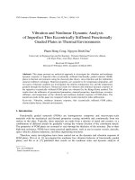
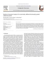
Table 7 and Fig. 2 illustrate the effect of semi-vertex angle β on critical
temperature load ∆Tcr . It can be seen that the critical thermal buckling load of
truncated conical shell strongly decreases when semi-vertex angle β increases. For
example, a orthogonal stiffened shell in Table 7, when the semi-vertex angle varies
20
ACCEPTED MANUSCRIPT
the values from 50 to 750 , the critical thermal load ∆Tcr decreases from 417K to 53K,
about 87.3%.
Graphically, the effect of semi-vertex angle β on critical temperature ∆Tcr is
plotted in Fig. 2. They also show that critical load ∆Tcr decrease when β increase and
RI
PT
the critcal load ∆Tcr - semi-vertex angle β curve for a orthogonal stiffened shell is
the highest.
450
1: Stringer, nst=30
2: Ring, nr=30
3
400
SC
2
1
3: Orthogonal, nst=nr=15
M
AN
U
∆ Tcr(K)
350
Outside stiffeners
h1=0.01375m, h2=0.01m
300
b1=0.0127m, b2=0.0127m
250
200
h=0.0127m, R1=1.27m, L=2R1,
150
TE
D
N=1, K1=0, K2=0
5
10
15
20
25
30
35
40
β (Degree)
EP
Fig. 2. Variation of the critical thermal difference versus β for ES-FGM conical
shells under uniform thermal load.
5.2.3. Effect of elastic foundations
AC
C
Effect of foundation on critical thermal load of ES-FGM conical shells under
uniform thermal load are show in Tables 8, 9 and Fig. 4.
Table 8 analyzes the influence of background factors K1 and K 2 on critical
thermal load (without stiffeners). We find that when we increase the value of the
(
)
coefficient K1 = 0;2 × 10⁷ ;3.5 × 10⁷ ;6 × 10⁷ N / m3 and keep the value coeficient K 2
or
reverse
the
effects
of
increased
compression
ratio
K 2 = ( 0; 2 × 10⁷ ;3.5 × 10⁷ ;6 × 10⁷ ) N / m and the ratio K1 unchanged, it makes the value
21
ACCEPTED MANUSCRIPT
of critical thermal load increase. Without elastic foundation ( K1 = K 2 = 0 ) the value of
critical thermal load is the smallest and K1 = 6 × 10⁷ N / m3 , K 2 = 6 × 10⁷ N / m is the
biggest.
Table 9 shows the value of the ground coefficient K 2 which affects the critical
greater than the ground coefficient
K1 = 0 N / m3 , K 2 = 2.5 × 10⁵ N / m
(Stringers)
results
K1 = 2.5 × 10⁷ N / m3 , K 2 = 0 N / m (Stringers) results
K1 . For example
RI
PT
∆Tcr
thermal load
∆Tcr = 240 K
and
∆Tcr = 237 K . And Table 9
SC
shows the critical thermal load of stiffened shell by stringers is the biggest, the
stiffend shell by orthogonal is the second and the critical thermal load of the stiffend
shell by ring stiffeners is the smallest.
M
AN
U
Table 8. Effect of foundation (without stiffeners) on critical thermal load ∆Tcr ( K ) ,
( h = 0.0127m, R / h = 100, L = 2R ,α = 30 , N = 1)
0
1
1
K1 ( N / m3 )
∆Tcr ( K )
3.5 × 10⁷
6 × 10⁷
205(8,9)
209(8,8)
212(8,6)
216(9,4)
2 × 10⁵
210(8,5)
214(9,4)
216(8,5)
220(8,8)
3.5 × 10⁵
212(8,9)
215(8,9)
218(8,7)
222(9,4)
217(8,5)
221(9,6)
223(8,5)
228(8,5)
EP
6 × 10⁵
TE
D
0
K2 ( N / m)
2 × 10⁷
0
AC
C
Table 9. Effect of stiffeners and foundations on critical thermal load ∆Tcr ( K ) ,
( h = 0.0127m, R1 = 1.27m, L = 2 R1 , h1 = 0.01375m, h2 = 0.01m, b1 = 0.0127m, b2 = 0.0127m )
Orthogonal
∆Tcr ( K )
28 Stringer
28 Ring
nst = nr = 14
K1 = 0 N / m3 , K 2 = 2.5 × 10⁵ N / m
240(8,5)
224(9,6)
232(8,6)
K1 = 2.5 × 10⁷ N / m3 , K 2 = 2.5 × 10⁵ N / m
244(8,6)
229(8,4)
237(8,7)
22
ACCEPTED MANUSCRIPT
K1 = 2.5 × 10⁷ N / m3 , K 2 = 0 N / m
237(7,12)
222(9,4)
233(7,15)
5.2.4. Effect of the volume fraction index N
The parameters for the stiffeners and the geometric parameters were chosen as
.
RI
PT
below:
h = 0.0127, R1 = 1.27 m, L = 2.54m, h1 = 0.03175m, h2 = 0.01m, b1 = b2 = 0.0127 m,
nst = nr = 15, K1 = 2.5 × 10⁷ , K 2 = 0
Table 10. Effect of the volume fraction index ( N ) and the semi-vertex angle β on
SC
critical temperature ∆Tcr ( K ) and FGM truncated conical shells under uniform
M
AN
U
thermal load.
N
10-2
100
3
101
5
102
5
557(8,16)
525(8,15) 420(8,16) 381(8,16) 369(8,15) 358(8,16) 341(8,15)
10
494(9,14)
464(8,15) 369(8,16) 334(8,15) 324(9,13) 313(9,12) 298(9,12)
30
320(8,8)
300(8,7)
203(8,10)
196(8,9)
1: β=5o
2: β=10o
Outside stiffeners
h1=0.01375m, h2=0.01m
3: β=30o
b1=0.0127m, b2=0.0127m
AC
C
450
210(8,4)
EP
550
500
234(8,10)
TE
D
600
∆ Tcr(K)
β
10-1
400
350
300
h=0.0127m, R1/h=100, L=2R1
250
200
150
0
2
4
6
N
23
8
10
186(8,2)
ACCEPTED MANUSCRIPT
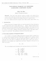
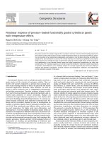
Fig. 3. Effect of the volume fraction index N on critical thermal load ∆Tcr .
Table 10 shows the changes in the values of the critical thermal loads when
changing volume ratio N . Figure 3 shows the variation of contact curve between the
critical heat load values - the coefficient of volumetric percentage in three cases
RI
PT
β = ( 50 ,100 ,300 ) . It can be seen that when the value N is increasing it makes the
critical temperature decreases. This is expected because the elastic modulus E of the
ceramic is much larger than the metal while the volume ratio of ceramic components
in the shell decreases when increasing N . Moreover, Figure 3 also shows the
SC
relationship curved between the critical temperature value - volume ratio coefficient
will be lowered if the semi - vertex angle β increases.
M
AN
U
5.2.5. Effect of the ratio R1 / h
Figure 4 shows the effect of radius ratio on the shell thickness ( R1 / h ) on the
critical temperature value and shells under the effect of temperature rising. We found
that if the ratio R1 / h is increasing, it will reduce the value of the critical temperature.
This is appropriate because the increasing ratio R1 / h will reduce h ( thinner shell)
TE
D
then make the ability of heat load low. The relationship between the ratio R1 / h and
the critical temperature in both stiffined case and un-stiffined case is also shown in
Fig. 4. It can be seen that in the absence of un-stiffined case will make the curve
AC
C
EP
becomes lower than stiffined case.
24