DSpace at VNU: Preparation and characterization of titanium dioxide nanotube array supported hydrated ruthenium oxide catalysts
Bạn đang xem bản rút gọn của tài liệu. Xem và tải ngay bản đầy đủ của tài liệu tại đây (479.85 KB, 6 trang )
Home
Search
Collections
Journals
About
Contact us
My IOPscience
Preparation and characterization of titanium dioxide nanotube array supported hydrated
ruthenium oxide catalysts
This content has been downloaded from IOPscience. Please scroll down to see the full text.
2012 Adv. Nat. Sci: Nanosci. Nanotechnol. 3 015008
( />View the table of contents for this issue, or go to the journal homepage for more
Download details:
IP Address: 80.82.77.83
This content was downloaded on 11/04/2017 at 10:26
Please note that terms and conditions apply.
You may also be interested in:
Structure and dye-sensitized solar cell application of TiO2 nanotube arrays fabricated by the
anodic oxidation method
Seon-Yeong Ok, Kwon-Koo Cho, Ki-Won Kim et al.
The large diameter and fast growth of self-organized TiO2 nanotube arrays achieved
viaelectrochemical anodization
H Yin, H Liu and W Z Shen
Fast-rate formation of TiO2 nanotube arrays in an organic bath and their applications
inphotocatalysis
Srimala Sreekantan, Khairul Arifah Saharudin, Zainovia Lockman et al.
Sonoelectrochemical synthesis of highly photoelectrochemically active TiO2 nanotubes
byincorporating CdS nanoparticles
ChengLin Wang, Lan Sun, Hong Yun et al.
The large-scale synthesis of 1D TiO2 nanostructures using palladium as catalyst at lowtemperature
Mingxia Xia, Qinglin Zhang, Hongxing Li et al.
A NiO/TiO2 junction electrode constructed using self-organized TiO2 nanotube arrays
Jin Guo, Wuyou Fu, Haibin Yang et al.
Enhanced biocompatibility of TiO2 surfaces by highly reactive plasma
Ita Junkar, Mukta Kulkarni, Barbara Drašler et al.
High-speed growth of TiO2 nanotube arrays with gradient pore diameter and ultrathintube wall under
high-field anodization
Xiaoliang Yuan, Maojun Zheng, Li Ma et al.
IOP PUBLISHING
ADVANCES IN NATURAL SCIENCES: NANOSCIENCE AND NANOTECHNOLOGY
Adv. Nat. Sci.: Nanosci. Nanotechnol. 3 (2012) 015008 (5pp)
doi:10.1088/2043-6262/3/1/015008
Preparation and characterization of
titanium dioxide nanotube array
supported hydrated ruthenium oxide
catalysts
Thi Phuong Ly Giang1 , Thi Nhu Mai Tran2 and Xuan Tuan Le3
1
University Paris-Sud, UMR-CNRS 8612, Laboratory of Proteins and Nanotechnologies in Separation
Sciences, 92296, Faculté de Pharmacie, Châtenay-Malabry, France
2
Faculty of Chemistry, Hanoi University of Science, Vietnam National University in Hanoi,
19 Le Thanh Tong Street, Hanoi, Vietnam
3
MiQro Innovation Collaborative Centre (C2MI), 45, boul. de l’Aéroport, Bromont (Québec), Canada
E-mail: and
Received 27 July 2011
Accepted for publication 26 September 2011
Published 6 March 2012
Online at stacks.iop.org/ANSN/3/015008
Abstract
This work aimed at preparing and characterizing TiO2 nanotube supported hydrated ruthenium
oxide catalysts. First of all, we succeeded in preparing TiO2 nanotube arrays by
electrochemical anodization of titanium metal at 20 V for 8 h in a 1M H3 PO4 + 0.5 wt% HF
solution as evidenced from scanning electron microscopy (SEM) and x-ray photoelectron
spectroscopy (XPS) results. The hydrated ruthenium oxide was then deposited onto TiO2
nanotubes by consecutive exchange of protons by Ru3+ ions, followed by formation of
hydrated oxide during the alkali treatment. Further XPS measurements showed that the
modified samples contain not only hydrated ruthenium oxide but also hydrated ruthenium
species Ru(III)-OH.
Keywords: TiO2 nanotube, anodization, hydrated ruthenium, catalytic oxidation.
Classification numbers: 2.03, 4.00, 5.06
a catalytic reaction. The semiconducting properties of such
new materials may result in strong electronic interaction
between the support and a catalyst, which could improve
catalytic performance in redox reactions [15]. As a result,
studies on supporting ruthenium-based compounds on TiO2
nanotubes are of potential interest [15–17]. In this sense,
this work focuses on preparation of titanium dioxide
nanotube array supported hydrated ruthenium oxide catalysts.
As a cost-effective and high rate method, the use of
electrochemistry to prepare TiO2 nanotube arrays is described
in the first section of the present paper. Part of the work is then
devoted to the loading of hydrated ruthenium oxides onto the
electrochemically anodized TiO2 nanotubes.
It is remarkable to note that as a promising new
catalyst for selective oxidation of many alcohols in aqueous
media, hydrated ruthenium oxides have frequently been
used in wastewater treatments [15]. However, the role of
1. Introduction
Incorporating metal-based species onto titanium dioxide
surface is one of the well-known methods to improve catalytic
activity of the resulting modified TiO2 materials [1–6].
Among various metals such as copper, nickel, tin, gold,
platinum, palladium ... the TiO2 supported Ru catalysts have
been proven to play an indispensable role with respect to
wastewater treatment and energy storage applications [7–10].
During the past ten years, TiO2 nanotubes have been widely
investigated due to their practical applications in areas such
as biomaterials, solar cell, rechargeable lithium batteries, gas
sensor, and catalysts in particular [1, 10–14]. Indeed, the
large cation exchange capacity of TiO2 nanotubes allows
a high loading of an active catalyst with even distribution
and high dispersion. The open mesoporous morphology of
the nanotubes, absence of micropores, and high specific
surface area should facilitate transport of reagents during
2043-6262/12/015008+05$33.00
1
© 2012 Vietnam Academy of Science & Technology
Content from this work may be used under the terms of the Creative Commons Attribution-NonCommercial ShareAlike 3.0 licence. Any
further distribution of this work must maintain attribution to the author(s) and the title of the work, journal citation and DOI.
Adv. Nat. Sci.: Nanosci. Nanotechnol. 3 (2012) 015008
T P L Giang et al
dissolved in 23 ml of water with addition of 2 ml of 0.5 M HCl.
Then TiO2 nanotube array samples were immersed in this
solution for 60 min at 25 ◦ C. After washing with a large
amount of DI water, the samples were put in a beaker
containing 1.0 M NaOH (Sigma Aldrich). After 1 h, the
samples were taken out of the solution, rinsed by DI water,
and then dried at 80 ◦ C under vacuum condition for 2 h.
2.3. Microscopy study
The SEM images were recorded by a Hitachi S4800 equipped
with a field emission gun (FEG-SEM).
2.4. XPS
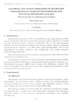
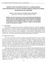
Figure 1. Two-electrode electrochemical cell for preparation of
TiO2 nanotube arrays.
XPS measurements were carried out with a Theta
300 (Thermo Scientific Instrument) equipped with a
microfocusing monochromator x-ray source. The data were
collected at room temperature, and the operating pressure
in the analysis chamber was always below 10−9 Torr. The
core level spectra were referenced to the pollution C 1 s
binding energy at 284.9 eV. Data treatment and peak-fitting
procedures were performed using Avantage software.
ruthenium supported catalysts towards methanol oxidation in
fuel applications is still an open topic for discussion [18, 19].
While some authors refer to the active ruthenium compound
mainly as metallic Ru0 in a bimetallic alloy, early research
revealed that hydrated ruthenium oxide as a part of bimetallic
Pt–Ru systems is the most active catalyst for methanol
oxidation [18]. It is thus interesting to investigate the
oxidation state of the Ru components deposited on our TiO2
nanotube arrays. In this work, the formation of Ru-based
species on the surface of TiO2 nanotubes will finally be
discussed as clearly as possible on the basis of x-ray
photoelectron spectroscopy (XPS) results.
3. Results and discussions
3.1. Electrochemical preparation of T i O 2 nanotube arrays
When a potential of 20 V is applied through the two-electrode
configuration described in the experimental section, first of
all, TiO2 is electrochemically formed (Ti + H2 O → TiO2 +
4e− ). Dissolution of titania then takes place thanks to the
presence of fluoride ions in the solution and leads to the
formation of soluble hexafluorotitanium complexes (TiO2 +
6F− + 4H+ → TiF2−
6 + 2H2 O). With the help of electrical field,
TiO2 nanotubes finally formed as a function of the time
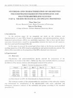
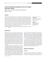
[20, 21]. Figure 2 presents the SEM images of the
resulting layers at different scales. The zoom-out SEM image
(figure 2B) clearly shows the self-organized nanotubes as
expected. It is also observed that the nanotube diameter is of
approximately 100 nm (figure 2C). Such an obtained result
is in a good agreement with the work of Bauer et al [22],
where the TiO2 nanotube diameter was reported to be linearly
dependent on the applied voltages and a diameter of about
100 nm was obtained with an applied potential of 20 V.
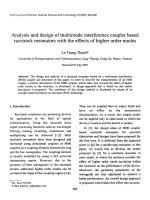
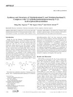
On the other hand, XPS measurements allow us to
confirm that the self-organized nanotubes are titanium
dioxide. As can be seen in figure 3 the survey spectrum of
the sample is dominated by signals of titanium and oxygen
as expected. Besides Ti and O peaks, we equally observe the
presence of unavoidable contaminated carbon peak. This peak
will be further discussed in the next section of this work. It
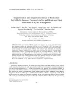
is important to point out that the Ti 2p core level spectrum
(figure 4(a)) shows the typical characteristics of titanium in
TiO2 with the 2p3/2 and 2p1/2 peaks centred at 458.8 and
464.3 eV, respectively [23].
XPS analysis also revealed that fluoride ions are strongly
absorbed on TiO2 surface, indicating the migration of F−
ions is driven by the electrical field (figure 4(b)). In fact,
under the influence of the electrical field, fluoride ions can
even penetrate into the bottom of the nanotube as reported
2. Experimental
2.1. Anodization of titanium metal
For the electrochemical anodization, a typical two-electrode
configuration (figure 1) was employed with platinum foil
as the counter electrode and titanium foil as the working
electrode. Thickness of titanium foils (99.6% purity) was
0.5 mm. Effective area of the O-ring on the working electrode
in contact with electrolyte solution (as shown in figure 1) was
1.0 cm2 . Prior to any electrochemical treatment the foils were
sonicated in acetone, isopropanol and methanol successively,
followed by rinsing with deionized (DI) water and drying in
a nitrogen stream. All anodization experiments were realized
at room temperature in a 1 M H3 PO4 (Merck) + 0.5 wt% HF
(Sigma-Aldrich) solution. A potential of 20 V was applied
through the system for 8 h. After each anodization, the
obtained sample was rinsed by DI water and dried in a
nitrogen stream. The as-anodized TiO2 nanotubes were then
recrystallized by heating at 400 ◦ C for 10 h under nitrogen
atmosphere. The obtained samples were characterized by
means of scanning electron microscopy (SEM) and XPS
techniques.
2.2. Deposition of hydrated ruthenium oxides onto T i O 2
nanotubes
The hydrated ruthenium oxide was deposited on TiO2
nanotubes by consecutive exchange of protons by Ru3+
ions, followed by formation of hydrated oxide during the
alkali treatment. 200 mg of RuCl3 ·3H2 O (Sigma Aldrich) was
2
Adv. Nat. Sci.: Nanosci. Nanotechnol. 3 (2012) 015008
T P L Giang et al
O 1s
Ti 2p
O KLL
Ti LMM
F 1s
F KLL
C 1s
40 kCPS
Ti 3p
1000
800
600
400
200
0
Binding Energy /eV
Figure 3. XPS survey spectrum of anodized TiO2 nanotube arrays.
a) Ti 2p
2p3/2
4 kCPS
2p1/2
468
466
464
462
460
458
456
Binding energy /eV
Figure 2. SEM images of TiO2 nanotubes formed at 20 V for 8 h in
1M H3 PO4 + 0.5 wt% HF at different scales.
b) F1s
elsewhere [24]. Furthermore, it should be kept in mind that
fluoride anions are involved in the dissolution process of TiO2
as mentioned above. Here, the most important point to be
underlined is that simple anodization of titanium metal led to
the formation of TiO2 film which consists of individual tubes
with a diameter of ≈100 nm as evidenced from the XPS and
SEM results.
500 CPS
3.2. Titanium dioxide nanotube array supported hydrated
ruthenium oxide catalysts
690
688
686
684
682
680
Binding energy /eV
Figure 5 shows the XPS survey spectrum of TiO2 nanotube
arrays supported Ru. As is seen here, the XPS survey spectrum
of TiO2 nanotubes modified with Ru-based species looks
very similar to that of pristine TiO2 nanotubes. We do not
observe clearly the presence of ruthenium on the spectrum.
This however can be easily understood by noting the fact that
the positions of Ru 3p are found to be very close to those
of Ti 2p and also the Ru 3d3/2 peak appears superposed to
the C 1 s line. In order to bing out the difference between
the two samples, we wish next to concentrate on the C 1 s
Figure 4. Ti 2p and F 1 s high-resolution spectra of TiO2 nanotube
arrays.
and C 1 s + Ru 3 d high-resolution spectra of the pristine and
modified samples.
Before modification with ruthenium, the C 1 s core level
can be fitted by three components located at 284.9, 286.4
and 288.8 eV respectively (figure 6(a)). After modification,
a typical behaviour of C 1 s + Ru 3 d mixed spectrum as
already reported in many published works [9, 25–27] is
3
Adv. Nat. Sci.: Nanosci. Nanotechnol. 3 (2012) 015008
T P L Giang et al
one, Ru2 (3d3/2 ) and Ru2 (3d5/2 ), locate at 282.1 and 286.3 eV.
Note that a separation distance of 4.2 eV between 3d3/2 and
5d5/2 peaks found for both pairs in this work is very close
to the expected value of 4.1 eV [26]. One can deduce that
there are two components of Ru-species on the surface of
the modified TiO2 nanotube. Nevertheless, discussion on the
nature of the two components is quite complicated. Mazzieri
et al [25] reported that by using RuCl3 as precursor for catalyst
preparation, ruthenium oxychloride species characterized by
3d3/2 peak at 280.9 eV are present on the sample surface.
In our case, it is however worth mentioning that we do not
observe any significant amount of chloride on the spectrum.
This allows us to exclude the presence of the chloride
compounds (ruthenium oxychloride and ruthenium chloride)
in our catalysts. Actually, the Ru component standing for
a 3d3/2 peak at 281.4 eV can be assigned to ruthenium in
RuO2 [26] or in RuO2 .xH2 O [28]. This peak is slightly
higher than our first Ru component (Ru1 (3d3/2 ) found at 281.0
in comparison with contaminated C peak of 284.9 eV). In
a separative work published by Bavykin et al [15], it was
reported that Ru(III)-hydrated oxide could be obtained on the
TiO2 surface through the same preparation process used in
the present work. On account of those facts, it is believed
that the first Ru component appeared at low binding energies
(281.0 and 285.2 eV) in our spectrum should be attributed to
the hydrated ruthenium oxides.
With the aim of clarifying the nature of the second
component with Ru2 (3d3/2 ) and Ru2 (3d5/2 ) binding energies
of 282.1 and 286.3 eV, it is important to note that the peaks
are not at all linked to RuCl3 as mentioned above. In this
case, the peaks can be attributed to the Ru (III) from hydrous
Ru (III) – OH incorporated on the lattice of TiO2 nanotubes
through the ion exchange reactions between the Ru3+ cations
in the solution and protons in the TiO2 nanotube framework.
Nanotubular ‘titanium dioxide’ is indeed a protonated form
of a layered titanic acid. The exact crystal structure of
the nanotubes is a matter of current dispute; it probably
corresponds either to the layered titanate H2 Ti3 O7 which has
a monoclinic structure with stepwise layers of three lengths
in each step, or to H2 Ti2 O4 (OH)2 in which the unit cell
has an orthorhombic symmetry. The nanotube walls have a
multilayered structure in which protons occupy positions on
either side of the wall surface (convex and concave), as well
as in the interstitial cavities between the layers of the nanotube
walls. Therefore, protons and cations from aqueous solutions
(H+ , Men+ ) could easily be exchanged for protons in the
nanotube wall, according to the following equation [15]:
O 1s
Ti 2p + Ru 3p
F 1s
C 1s + Ru 3d
5 kCPS
1000
800
600
400
200
0
Binding energy /eV
Figure 5. XPS survey spectrum of TiO2 nanotube arrays supported
Ru.
CPS /a.u.
a) C 1s
C3
C2
C1
290
288
286
284
282
280
Binding energy /eV
b) C1s + Ru 3d
C3
CPS /a.u.
C2
C1
Ru1(3d5/2)
Ru1(3d3/2)
Ru2(3d5/2)
Ru2(3d3/2)
290
288
286
284
282
280
Binding energy /eV
xMen+ + H2 Ti3 O7 → Mex H2−x Ti3 O7x(n−1)+ + xH+ .
Figure 6. (a) Decomposed C 1 s core level spectra of pristine TiO2
nanotubes. (b) Decomposed C 1 s and Ru 3 d core level spectra of
TiO2 supported Ru nanotubes.
The obtained XPS data indicate that the resulting
Ru/TiO2 nanotube arrays contain both hydrated ruthenium
oxide and hydrated ruthenium species Ru(III)-OH.
depicted in figure 6(b). As expected, in addition to the C
peaks which are quasi-identical to those of the pristine sample,
the Ru 3 d peaks appear in the spectrum. In particular, the
Ru 3 d core level spectrum is characterized by 2 pairs of
relatively narrow peaks which correspond to the 5/2 and 3/2
spin–orbits (the red and black lines presented in figure 6(b)).
The first pair of 3 d peak, Ru1 (3d3/2 ) and Ru1 (3d5/2 ), are
found at 281.0 and 285.2 eV, respectively while the second
4. Conclusion
A one-step electrochemical method has been used to
prepare TiO2 layers that consist of arrays of individual
tubes with a diameter of ≈100 nm. Thanks to the ion
exchange reaction between the proton of the protonated
4
Adv. Nat. Sci.: Nanosci. Nanotechnol. 3 (2012) 015008
T P L Giang et al
form of a layered titanic acid and Ru3+ cation in the
bulk solution, hydrated ruthenium species Ru(III)-OH can
be easily incorporated on TiO2 nanotube surface. Part of
such a ruthenium species was subsequently converted to
hydrated ruthenium oxide by simple alkali and thermal
treatments. Aside from Ru(III)-OH species, XPS allowed us
to evidence the presence of hydrated ruthenium oxide on
the surface of supported Ru/TiO2 nanotube catalysts. As
mentioned in the introduction, supported Ru/TiO2 catalysts
have been proven efficient in the selective oxidation of several
organic alcohols. Testing the catalytic activity of the obtained
Ru/TiO2 nanotube catalysts is obviously the subject of our
further works.
[11] Song Y-Y, Schmidt-Stein F, Bauer S and Schmuki P 2009
J. Am. Chem. Soc. 131 4230
[12] Mor G K, Shankar K, Paulose M, Varghese O K and Grimes
C A 2006 Nano Lett. 6 215
[13] Zhang Q, Dandeneau C S, Candelaria S, Liu D, Garcia B B,
Zhou X, Jeong Y-H and Cao G 2010 Chem. Mater. 22 2427
[14] Song H, Qiu X, Guo D and Li F 2008 J. Power Sources 178 97
[15] Bavykin D V, Lapkin A A, Plucinski P K, Friedrich J M and
Walsh F C 2005 J. Catal. 235 10
[16] Liming W and Binghua Y 2010 4th Int. Conf. on
Bioinformatics and Biomedical Engineering (4th iCBBE,
18–20 June 2010, Chengdu, China) Proc. ed W Lu
(Piscataway, NJ: IEEE)
DOI.:10.1109/ICBBE.2010.5514829
[17] Bandara J, Shankar K, Basham J, Wietasch H, Paulose M,
Varghese O K, Grimes C A and Thelakkat M 2011 Eur.
Phys. J. Appl. Phys. 53 20601
[18] Gomez de la Fuente J L, Martinez-Huerta M V, Rojas S,
Hernadez-Fernandez P, Terreos P, Fierro J L G and Pena
M A 2009 Appl. Catal. B 88 505
[19] Huang S Y and Yeh C T 2010 J. Power Sources 195 2638
[20] Ghicov A, Tsuchiya H, Macak J M and Schmuki P 2005
Electrochem. Commun. 7 505
[21] Liu Y, Zhou B, Li J, Can X, Bai J and Cai W 2009 Appl. Catal.
B 92 326
[22] Bauer S, Kleber S and Schmuki P 2006 Electrochem.
Commun. 8 1321
[23] Moulder J F, Stickle W F, Sobol P E and Bomben K D 1992
Handbook of X-Ray Photoelectron Spectroscopy (Eden,
Prarie, MN: Perkin-Elmer)
[24] Li D, Chang P-C, Chien C-J and Lu J G 2010 Chem. Mater.
22 5707
[25] Mazzieri V, Coloma-Pascual F, Arcoya A, L’Argentiere P C
and Figoli N S 2003 Appl. Surf. Sci. 210 222
[26] Rochefort D, Dabo P, Guay D and Sherwood P M A 2003
Electrochim. Acta 48 4245
[27] Mun C, Ehrhardt J J, Lambert J and Madic C 2007 Appl. Surf.
Sci. 253 7613
[28] Kim K S and Winograd N 1974 J. Catal. 35 66
References
[1] Varghese O K, Paulose M, LaTempa T J and Grimes C A 2009
Nano Lett. 9 731
[2] Yu K-P, Yu W-Y, Kuo M-C, Liou Y-C and Chien S-H 2008
Appl. Catal. B 84 112
[3] Torrente-Murciano L, Lapkin A A, Bavykin D V, Walsh F C
and Wilson K 2007 J. Catal. 245 272
[4] Luu C L, Nguyen Q T and Ho S T 2010 Adv. Nat. Sci.:
Nanosci. Nanotechnol. 1 015008
[5] Vu A T, Nguyen Q T, Bui T H L, Tran M C, Dang T P and Tran
T K H 2010 Adv. Nat. Sci.: Nanosci. Nanotechnol. 1 015009
[6] Dang T M D, Nguyen T M H and Nguyen H P 2010 Adv. Nat.
Sci.: Nanosci. Nanotechnol. 1 025011
[7] Perkas N, Pham M D, Gallezot P, Gedanken A and Besson M
2005 Appl. Catal. B 59 121
[8] Pham M D, Aubert G, Gallezot P and Messon M 2007 Appl.
Catal. B 73 236
[9] Elmasides C, Kondarides D, Grunert W and Verykios X E
1999 J. Phys. Chem. B 103 5227
[10] Grimes C A 2007 J. Mater. Chem. 17 1451
5