DSpace at VNU: Optical Bistability Effect in DFB Laser with Two Cections
Bạn đang xem bản rút gọn của tài liệu. Xem và tải ngay bản đầy đủ của tài liệu tại đây (3.12 MB, 8 trang )
V N U . J O U R N A L O F S C IE N C E , M a th e m a tic s - Physics. T .X X II, N q 2 - 2 0 0 6
O P T I C A L B IS T A B IL IT Y E F F E C T IN
D F B L A S E R W IT H T W O S E C T IO N S
N gu yen Van Phu*, D inh Van H oangt, C ao Long V an#
* Faculty o f Physics, Vinh University
t Faculty o f Physics, Hanoi N ational University
ft In stitu te o f Physics, University o f Zielona Góra
Podgórna 50, 65-246 Zielona Góra, Poland
In this paper the optical bistability in DFB laser with two sections has
been demonstrated. Influence of some dynamical laser parameters involved in the
problem (as current intensity, saturation coefficient and gain values) on this effect
has been considered.
A b stra c t.
1. I n tr o d u c tio n
As known, the large num ber of DFB (distributed feedback) lasers used inside a
transmitter makes the design and m aintenance of such a light wave system expensive and
impractical. T he availability of sem iconductor lasers which can be tuned over a wide
spectral range would solve this problem. One of these is m ulti-(tw o or more) section DFB
laser, considered theoretically and experimentally during 1980s [l]-[ 7 ], [13]-[18] and were
used in commercial lightwave system s by 1990.
On the other hand, optical bistability effect, discovered since the 1970s in different
optical systems w ith the possibility of its applications as an optical switch (or ’optical
tran sisto r’), an optical differential amplifier, optical lim iter, optical clipper, optical dis
crim inator, or an optical m em ory element, has given rise to a large num ber of different
theoretical and experim ental treatm ents. Because of m any special advantages of utilizing
semiconductors as optical bistable elements, the most efforts of researchers in the field of
optical bistability have been focused on developing various sem iconductor m aterials and
devices [19].
In this paper we propose ones of theses devices: a DFB sem iconductor laser with
two sections. In Section II, startin g from dynamical equations describing this laser we
have received th e exhibition of optical bistability effect in the stationary sta te limit. The
influence of some dynam ical laser param eters on this effect are dem onstrated in Section
III. Section IV contains conclusions.
Typeset by
47
N g u y e n Van P hu, D in h Van H o a n g , C ao Long Van
48
2. System o f rate equations—
The operating characteristics of semiconductor lasers are described by a set of rate
equations th a t govern the interaction of photons and electrons inside the active region. A
rigorous derivation of the rate equations generally sta rts from Maxwell s equations together
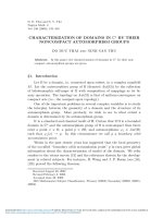
with a quantum -mechanical approach for the induced polarization. A DFB laser with two
sections is shown schematically in figure 1. Here, section A with injection current I\ IS an
amplifying section, section B with injection current /2 much smaller than 11 takes a. role
as a saturable absorber section.
F i g .l . Schematic illustration of a DFB laser with two sections.
Then we have the following system of rate equations:
dt
eVi
-
m —
n ef f
g ip
0
-
W jfri -
m N i
(!)
~0r =
~ m - ^ - 9 ( u 0 - u>j)nj - 7 2 JV2
dt
eV2
rieff
at
(2)
= (r ar/i + r 2T?2) - ^ - ỡ (w0 - Wj)(nj + 1) - 7nj +
n ef f
Here Vi v 2 N i , N 2 are the volumes and carrier densities of sections A , B corre
spondingly;
Ti j
is photon density; e, Co
in v a c u u m ;
Tieff
is t h e
effective
are
refraction
electric charge of electron and velocity of light
in dex
of m aterial,
supposed
to
be
t h e s a m e for
two sections; T]i is the amplification coefficient, which depends on the carrier density in
the form rji = aịNị + Pi, where ai,Pi are material gain coefficients (i = 1,2); 71,72 are
relaxation coefficients of carrier densities given in the form [8]
B qN i
72
B oN i
e i - B 2N 2 ’
with So B\ B2 are material coefficients, £ is saturation coefficient indicating the different
relaxations of carrier densities between two sections; r i , r 2 are confinement factors or
Peterm an coefficients in sections A and B\ 7 is coefficient which describes the photor. loss
O ptical b ista b ility effect in D F B la se r w ith tw o s e c tio n s
49
in section A , D and mirrors; Function g(u>0 - c j j ) describes the broadening of spectral laser
line which is given in the form of Lorentzian:
g(uj0 - U!j) = ------ y — - 2
i + ( ^ )
with r is the w idth of the gain line; A j = U)Q - Uj is detuning factor; Ct»0,Uj are circular
frequencies in the center of the gain line and of j th mode. The unity in factor (rij +
1) indicates the presence of spontaneous emission in laser operation and the last term
p y/rijK ) deals with the interaction of signal and laser radiation. The interaction coefficient
/3 is usually taken to be unity (p — I s - 1 [7]-[8]).
In the stationary regime, we put all time derivatives in (1),(2), (3) to
obtain:
zero and
0 = r t \ ~ m w y f ỡ(w0 - w > j - 7 i W i ,
(4)
0 = eV2 ~ V2w y f 9^ 0 ~ Uj )ni ~ 7a7V2’
0 = (ri7?i + r 2772) - ^ - 5(^0
n ef f
- Uj)(nj +
1) - 7 Uj + Py/p~n~j.
(6 )
We suppose also th a t (3i = 0, which is usually valid for the most of semiconductor
lasers used in practice (e.g. InGaAsP, see [7], [8]) and we also suppose to ignore
the
presence of spontaneous emission. It follows from (4), (5), ( 6 ) th at
A n ] '2 - E n ) /2 + C n 3/ 2 - D n )/2 + p y /P ^G rij - p ự K Q n ] - ậ y f p u = 0,
where the coefficients A , E , c , D, G, Q are given by:
r i a ? a 2^4ổ4eV15 2
r 2a i a ^ V e V '25 1
A iB lT n
+
4 ££ 02T 22
r _ r ia ? i/3g 3eVj
ABoTn
r 2a ịi/3g3eV2
4£B 0T22
T i a Ị a 2iy3g 3I i B i B 2 r 2a i a ^ V ^ 2 - S i 5 2
2£5 02T n
+
2£B gr22
r 1a Ị a 2i'3g 3B 2 + TiOLiáịv*g2B i - 270'ia 2ỉ' 2ỡ2 B ị B 2
kẻl
T.aW^hB,r2a|i/V/2fl2 Txa\vWZ + r2a2V g2
2 B 0T n
2£B0T22
2£ B 0
T l a 1a 2v 2g2B 2 rr
T 2a ia 2 ^ 2g2B l rr
2^5^eVi
11 +
2ZB2
0 eV2
22
YiOtiGt2V2g2h B \B 2
T20i\0i2V2g2h B \B 2
^ B le V x
2ỊB Ịẽ V 2
r i _ T i a i ug r 2a 2vg
T iC tiyg liB i
2B 0eVi 11
2Ì B ữeV2 22
2B 0eVi
'yaii'gBiZ +
7 0 2 ^5 ^ 2
£B 0’
Y2a 2V9 h B i
2£B 0eV2
7’
(7)
N g u y e n Van P h u , D in h Van H o a n g , C a o L on g Van
50
Or
—
ctịvgB i
Bo
0C2vgB2 n _ OL\a.2V2g2B \B 2
(B o
----- „ ---------1-------; V —
Co
u = r — ; 9 = 9{v 0 - Wj),
n e //
Tn =
^ /
4
/ 1
flo e V
i
+
ĩịẼị]
r
22
=
y/^I2B0eV2
+
/ f B
f .
W hen the external optical signal disappears (Pw = 0), we obtain from (7)
( 8)
A rP j - EVij 4- C rij - D = 0.
For the most of sem iconductor lasers used in practice we have also [7] V\ = V2 — V,
B \ = B 2 — B C*1 = c*2 = Ct. We consider for simplicity the resonance case in which the
generating mode frequency coincides with Uo, then we have
g( uo- Wj ) = 1.
and obtain finally:
(9)
Hj — 'Hrij + Crij —M = 0,
where:
n =
c=
Bo
D
(F1T22 + r2r„) + ^(ri/iT22+ r2T2Tu) + 2 TllTẠ-(riaỉy+r2au - 27Ổ)
2
a u eV
B o t e T ^ T n + T2I2T n ) + B °T" T™m
B T uT aa
eK
=
B
ỰiTi + /2r2) +
2 BqT\\T22
a 2u2eV
av
+1}
+ r2) +
(IY T n
+ r2T22)
/ 7I
n
IT
g^(fr,rn + r2r22) - jLfc/.r, + J3r2) - e§°
/T
T = a u { T 1T22 + T2T n ) i
The Eq.
(9) represents the catastrophe manifold of the Riemann-Hugoniot (or
‘cusp’) catastrophe A s in the M ather-Thom classification [20]. T his catastrophe is given
by the following potential function V(x\ a, b):
V( x \ a, b) — - X 4 + - a x 2 + bx.
( 10 )
The physical system described by this potential function has evolution generated
by variations in the control param eters a = L - V.2/2),b = ;H C/ 3 - M - 27i3/27. The
O ptical b is ta b ility effe ct in D F B la se r w ith tw o se c tio n s
51
system, in accordance with the general principle of minimization of potential energy, will
tend to dwell on the catastrophe surface M 3 given by
M
3 = { ( x , a , b) : X 3 + a x + b = 0 } .
The set of degenerate critical points £ 3, defined by the condition of having multiple
roots by the polynomial w( x ) = X3 4- a x 4- 6, is expressed by
£3
= { ( x ,a , 6 ) : X3 + a x + b = 0 ,3 x 2 4- a =
0}
.
(11)
The X variable may be eliminated from the system of equations defining the set E 3.
Then we obtain the bifurcation set z?3 given by:
B 3 = {(a, b) : 4a 3 4- 2762 = 0}.
This set determ ines the param eters range involved in the problem for which the bistablity
e f f e c t o c c u r s . T he left side of (9) is an universal unfolding of the function f(rij) = nJ which
is structurally stable: th e small change of the control param eters (physical param eters
involved in the problem ) do not change the form of the hysteresis curves as we will see in
the next Section.
3. Influence o f som e dynam ical param eters on optical bistab ility effect
3 .1 . T h e a p p e a ra n ce o f o p tic a l b ista b ility e ffe c t
We can now solve numerically the equations (7), ( 8). The values of the param eters
involved in the problem are taken from the experimental d a ta for a concrete semiconduc
tor laser on InG aA sP given by K inoshita [7] and Yong-Zhen Huang [8]: Co = 3.10 10cm .s_1;
e = 1,6.1(T19C; Vi = 84.10- 12cm3; v 2 = 84.10“ 12cm3; B 0 = 10~10cm 3.s’ 1]
D \ = 5.10~ 19cm3; £?2 = 5.10“ 19cm3; n ef f = 3.4; C*1 = 4.10“ 16cm2; c*2 = 4.10~ 16cm2;
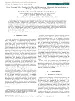
£ — 0. 1 ; r 1 = 0 .5 ; r2= 0.2 ; 7 = 1 , n.io^s1; Pi = 0; 0 = 1 s ” 1; p„ = 1022cm"3 .
110°
InjecUoncurrenl I^(A)
F ig . 2 . Hysteresis curve of optical bistability effect in DFB laser with two sections.
N g u y e n Van P h u , D in h Van H o a n g , C ao Long Van
52
In the MATLAB language, we have received a hysteresis curve of optical bistability
effect shown in Fig. 2. Here injection current I\ is control param eter and distance X1X2
indicates the width of bistability (BSW).
3 .2 . T h e c h a n g e o f th e in je c tio n c u r r e n t /2
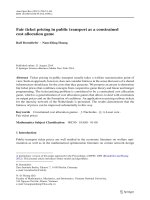
It follows from Fig. 3, th a t when /2 increases, the bistability w idth (BSW) increases
too. For clearness we take three values of /2 : 2 X 10“ 5Ẩ,2.5 X 10- 5 A ,2.8 X 10- 5i4. The
corresponding curves are presented in Fig. 3: The dotted line corresponds to the value of
/2 = 2 X 10⁻⁵ j4, the dashed and solid lines correspond to the values of /2 = 2.5 X 10~5A
and /2 = 2.8
X
10” 5A T he results are given in the Table I.
T ab le I
h(A)
2
BSW(A)
0.1543
X
2.5
10~5
X
10~5
2.8
0.4423
X
10~5
1.3486
F ig . 3. Influence of injection current /2 on hysteresis curves of optical bistability effect.
Other values of I '2 are /2
=
2
X
10 “ 5j4 , Ì 2
—
2.5
X 1 0 “ 5 i 4 , /2 =
2.8
X
10“ 5A
3 .3 . In flu e n c e o f th e s a tu r a tio n c o e ffic ie n t £
Choosing three values of £ we also obtain the hysteresis curves and optical bistabilty
effect is dem onstrated in Fig. 4. W hen £ rises the BSW diminishes. The results are given
in Table II.
T ab le I I
£
0.1
0.15
0.2
BSW(A)
0.4354
0.2194
0.1343
O ptical b ista b ility effect in D F B la se r w ith tw o s e c tio n s
53
*10”
F ig . 4. Influence of saturation coefficient £ on BSW of hysteresis curves
3 . 4 . Influence o f the gain value a
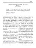
In this case the curves of optical bistability are presented in Fig. 5. Prom this Fig.
we s e e th a t when the gain value a increases the BSW increases too. The numerical results
are given in Table III.
T a b le III
a ( c m 2)
3
BSW(A)
0.4354
X
10- 16
4
X
1(T 16
0.6857
5
X
10- 16
1.12 11
I io ’3
F ig . 5. Influence of gain values a on hysteresis curves of optical bistability effect.
N g u y e n Van P h u , D in h Van H o a n g , C ao L ong Van
54
5. C onclusions
From above obtained results we derive the following conclusions:
1. Optical bistability effect appeared like in the case of lasers containing saturable
absorber (LSA) [16]. Here, the decisive condition for having hysteresis curves of OB effect
is the current Ỉ 2 in section B m ust be much smaller than current I \ in section A.
2. Laser parameters as gain, saturation coefficients, etc ... will be control parameters
for hysteresis curves. T he change of dynamical param eters involved in the problem clearly
influences on characteristics of optical bistability effect as the bistability width or the
optical bistability height. D eterm ination of the .values of these param eters, which give the
large bistability w idth for DFB laser is very im portant from experim ental and practical
point of view.
In fact, the change values of laser param eters as gain, saturation coefficients, etc... can be
realized by changing proportion of X or y in structure I n \ - xG axA s y P \-y of m aterial.
5. References
1. Dinh Van Hoang et al., M odem problems in Optics and Spectroscopy, II, 406 (2000).
2. G. M orthier and p. Vankwikelberge, Handbook of Distributed Feedback Laser Diodes,
Artech House, Norwood, MA 1999, p. 1792.
3. A. Lugiato, L. M. Narducci, Phys. Rev. A 32, 1576 (1985).
4. D. Dangoisse et al., Phys. Rev. A 42, (1990) 1551.
5. H. Wenzel et al., IE E E J. Quantum Elec. 32, 69 (1996).
6 . B. Sartorius et al., IE E E J. Quantum Elec. 33, 211 (1997).
7. J. Kinoshita, IE E E J. Quantum Elec. 30, 928 (1990).
8 . Yong-Zhen H uang,IE E E Photonics Tech. Lett. 7, 977 (1995).
9. H. Onaka et al., in: Optical Fiber Communication (O F C ’96). Post deadline papers,
P art B, San Jose, 25 Feb.-l Mar., pp. PD 19-1/5.
10. G. P. Makino et al., in: Optical Fiber Communication (O F C ’96). Technical Digest,
Vol. 2, San Josfe, 25 Feb.-l Mar., pp. PD 298-142.
11. I. Jiondot and I. L. Beylat, Electron Lett. 29, 604 (1993).
12. S. M. Sze, Physics o f semiconductor devices, 2nd ed., Wiley, New York 1981.
13. K. Seeger, Sem iconductor Physics, Springer-Verlag, Berlin 1985.
14. M. Asada et al., IE E E J. Quantum Elec. 17, 947 (1981).
15. K. Iga and s. K inoshita, Process technology fo r semiconductor laser, Springer series
in m aterials science, New York 1996.
16. P.Q. Bao, D .v . Hoang and Luc, J. of Russian Laser Research, Kluwer A cadem ic/Plen
Publishers, Vol. 20, No. 4, 297 (1999).
17. G. P. Agrawal, Fiber-Optic Communication System s, 3rd ed., John Wiley & Sons,
inc., New York 2002.
18. M. Ohstu, Frequency Control of Semiconductor Lasers, Wiley, New York 1996.
19. G .s. He, S.H. Liu, Physics of nonlinear optics, World Scientific Publishing Co. Pte.
Ltd, Singapore 1999, C hapter 12.
20. G. Gilmore, Catastrophe Theory fo r Scientists and Engineers, New York 1981.