Side information creation using adaptive block size for distributed video coding
Bạn đang xem bản rút gọn của tài liệu. Xem và tải ngay bản đầy đủ của tài liệu tại đây (336.96 KB, 5 trang )
2016 International Conference on Advanced Technologies for Communications (ATC)
Side information creation using adaptive block size
for distributed video coding
Nguyen Thi Huong Thao, Vu Huu Tien
Hoang Van Xiem, Le Thanh Ha, Dinh Trieu Duong
Posts and Telecommunications Institute of Technology
Ha noi, Vietnam
Email: thaonth,
Vietnam National University
Ha noi, Vietnam
Email: xiemhoang, lthavnu,
Abstract—Distributed video coding is the promising solution
for emerging applications such as wireless video surveillance,
wireless video sensor networks that have not been supported by
traditional video coding standards. Success of distributed video
coding is based on exploiting the source statistics at the decoder
with availability of some side information. The better the quality
of side information, the higher the performance of the distributed
video coding system. In this paper, a novel side information
creation method is proposed by using different block sizes based
on the residual information at the encoder. The proposed solution
is compared with the previous PRISM solution and simulated
results show that the proposed solution robustly improves the
coding performance in some cases of test sequences.
Keywords—Distributed Video Coding, Side Information.
I.
I NTRODUCTION
Today, video standards play an important role in many
applications in life. Almost all of the video coding applications
fall within the two classes of application models, namely
downlink and uplink models. The downlink application model
is associated with the broadcasting approach. In this model,
the encoder complexity may be high while decoder complexity
needs as light as possible because there may be one encoder but
thousands of decoders. Applications such as video streaming,
broadcasting belong to this downlink model. On the other
hand, in the uplink application model, low complexity encoder
is required and complexity of the decoder is not issue. Emerging applications such as wireless video surveillance, wireless
video sensor networks belong to this model.
However, popular video coding standards such as MPEGx,
H.264/AVC or HEVC only mainly support for downlink application models. So, what are solutions for uplink application
models? The answer for this question is Distributed Video
Coding (DVC) solution. Based on two important results of
information theory are the Slepian-Wolf [1] and the WynerZiv [2] theorems, DVC is regarded as the promising solution
for the uplink application model because it only exploits
the redundancy, partially or fully, at the decoder with the
availability of side information (SI) rather not at the encoder as
predictive coding standards earlier. So, motion estimation task,
that requires high computational complexity, is not performed
at encoder and this makes the encoder lighter. Theoretically,
DVC can achieve compression performance equals to the
current video standard. However practical DVC systems have
much work to do to achieve such performance. As we see,
DVC only works well if SI is available at decoder and the
better the quality of SI, the smaller the number of parity bits
978-1-5090-2710-1/16/$31.00 ©2016 IEEE
339
(or bit rate) needed. In the literature, there have been many
SI creation proposals, notably frame interpolation [3,4] and
extrapolation [5,6] algorithms. Frame interplolation methods
use past and future decoded frames to creat SI so there is some
delay. Howerver, frame extrapolation methods use only past
decoded frames so the delay is lower and it is more suitable
for real time applications. SI creation techniques at the decoder
are responsible for the compression efficiency in the DVC,
therefore building the more efficient novel SI creation method
is very necessary for DVC systems.
The first pratical implementations of DVC systems have
been proposed in [7] and [8], namely Berkeley and Stanford architectures correspondingly. In [7], PRISM codec is presented
based on pixel block syndrome coding. In [8], a codec based
on turbo codes operating on whole frame have been proposed.
In this paper, a SI creation algorithm with high quality and
reasonable computional time based on PRISM architecture is
proposed. The rest of paper is organized as follows. Section 2
briefly describes about PRISM architecture and some related
works. In section 3, a novel SI creation method at the decoder
is proposed and finally, test conditions and performance results
are presented in section 4.
II.
PRISM ARCHITECHTURE
The PRISM codec (Power-efficient, Robust, hIghcompression, Syndrome-based Multimedia coding) works at
block level, i.e., channel codes are applied independently for
each block, with motion estimation performed at the decoder
and CRC used to identify correct SI, and especially does not
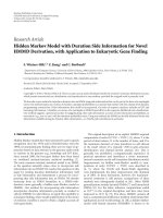
require a feedback channel. The PRISM codec is shown in
Figure 1.
At the encoder:
Classification: Before encoding, each block is classified
into one of several pre-defined classes depending on the
temporal correlation between the current block and the corresponding prediction block in the reference frame. Depending
on the allowed complexity at the encoder, prediction block
can be either the co-located block or a motion compensated
block. This stage decides to which class the block belongs
and so the coding mode for each block: no coding (SKIP
class), traditional Intraframe coding (entropy coding class)
or syndrome coding (several syndrome coding classes). The
blocks classified in the syndrome coding classes are coded
using DVC coding approach as described below.
2016 International Conference on Advanced Technologies for Communications (ATC)
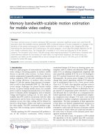
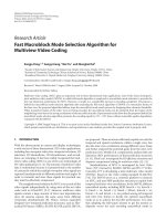
Fig. 2.
The encoder of the proposal architecture
decoded quantized block is thus obtained from the syndrome
decoding operation.
Hash check: Each candidate block leads to a decoded
block, from that a CRC is generated for each decoded quantized block. To select one of candidate blocks and successful
decoding (i.e. blocks with a small error probability), generated
CRC is checked sequentially until decoding leads to CRC sum
matching.
Fig. 1.
(a) Encoder block diagram; (b) Decoder block diagram
DCT: A frame is divided into non-overlapped blocks and
Discrete Cosine Transform (DCT) is applied over each block.
Quantization: A scalar quantizer [9] with fixed step size
as in H.263+ is applied to the obtained DCT coefficients
corresponding to a certain target quality.
Syndrome coding: For those blocks classified in the syndrome coding classes, only the least significant bits of the
quantized DCT coefficients in a block are syndrome encoded,
so it is assumed that the most significant bits are inferred from
the SI (due to high correlation with the corresponding SI).
The number of least significant bits to be transmitted to the
decoder depends on the syndrome class to which the block
belongs. Within the least significant bits, the lower part of
the is encoded using a (run, depth, path, last) 4 tuple based
entropy codec. The upper part of the least significant bits is
coded using a coset channel code, in this case a BCH code,
because it works well for small block length.
Hash generator: For each block, the encoder also send a
16 bit cyclic redundancy check (CRC) sum as a signature of
the quantized DCT coefficients. CRC is used to select the best
candidate block (SI) at the decoder as explained below.
At the decoder:
Motion search: The decoder generates side information
candidate blocks, which correspond to all half-pixel displaced
blocks in the reference frame, in a window positioned around
the center of the block to decode.
Syndrome decoder: Each of the candidate blocks plays
the role of side information for syndrome decoding, which
consists in two steps [9]: The first step deals with entropy
decoding of the lower part of the least significant bitplanes
and the coset channel coded bitplanes to identify the coset in
which the SI must be decoded. The second step deals with
soft decision decoding which is performed for each candidate
block (SI) to find the closest (quantized) codeword within the
coset identified in the first step. For each candidate block, a
340
Reconstruction and IDCT Once the quantized DCT coefficients block is recovered, it is used along with the corresponding side information to get the best reconstructed block
by using the minimum mean square estimate from the side
information and the quantized block. The decoded video frame
is then obtained applying the IDCT over the reconstructed
(DCT coefficients) block.
III.
P ROPOSAL A RCHITECTURE OF D ISTRIBUTED V IDEO
C ODING
Motivated from solution in [10], the proposed architecture
uses the H.264/AVC standard in order to exploit the enhanced
coding solutions of the standards. This solution is also based
on the early DVC architecture briefly presented in Section
2. As mentioned above, DVC coding approach targets the
reduction of the encoder computational complexity, which is
typically high for predictive video coding architectures. In
addition, the method in [10] uses correlation estimation of
4x4 input blocks for all frames in video sequences. In order
to descrease encoding time moreover, the proposed method
uses the adaptive input block size to enhance the performance
of DVC codec. The proposed architecture of video coding is
shown in Figure 2.
A. Encoding process
In this paper, the encoding process is performed in the
following steps:
Frame classification: First, a video sequence is divided into
WZ frames, this means the frames that will be coded using a
Wyner-Ziv approach, and key frames that will be coded as
Intra frames, e.g. using the H.264/AVC Intra coding mode
[10]. The key frames are typically periodically inserted with
a certain GOP (Group Of Picture) size. An adaptive GOP
size selection process may also be used, meaning that the
key frames are inserted depending on the amount of temporal
correlation present along the video sequence. In this paper, we
use a GOP size of 2, which is used in most results available
in the literature, it means that odd and even frames are key
frames and Wyner-Ziv frames, respectively.
2016 International Conference on Advanced Technologies for Communications (ATC)
Selecting the size of block by correlation estimation of
adaptive input blocks: In [10], for each 4x4 input block, the
encoder estimate the correlation level with the side information
in order to permit a correct decoding. At the decoder side,
the candidate predictors are created by motion search the
current block 4x4 with a search window of 16x16 pixels
in the previous frame. In the situation when the correlation
between Wyner-Ziv frame and the previous Intra frame is high,
it means Wyner-Ziv frame is quite similar to the Intra frame, so
encoding time can be decreased by using higher size of block.
In the proposal architecture, the size of input blocks is assigned
for each Wyner-Ziv frame depending on the MAD (Mean of
Absulutely Difference) between the Wyner-Ziv frame and the
previous Intra frame and computed as shown in Eq(1).
S=
4x4
8x8
if
if
MAD ≤ threshold
MAD > threshold
(1)
where S is the block size. If MAD ≥ threshold, we consider
that the correlation is low and thus, in order to correctly recover
the Wyner-Ziv frame at the decoder, 4 x 4 size of block is used.
If MAD < threshold, it means that the correlation is high and
thus,the 8 x 8 block size is used. In this method, threshold is
average of MAD of previous frames.
Transform: After the block size of each Wyner-Ziv is
selected, each video frame is divided in to 4 x 4 or 8 x 8
depending on the previous step and a DCT is applied over
each block. DCT is used to exploit spatial redundancy in image
blocks.
Quantization: A scalar quantizer is applied to the obtained
DCT coefficients to increase compression efficiency corresponding to certain target quality.
Syndrome generation: With a block of quantized DCT
coefficients, we compute luminance average of the current
block and transform it to 8 binary bits, namely xi,j where
(i, j) are coordinates of the current blocks center. For the sake
of simplicity and descreasing computional time, xi,j is divided
into two parts, namely most significant bits (MSB) and least
significant bits (LSB). These MSB bits will be inferred from
the side information at the decoder since it is believed that
there is very high correlation for these bits; so these bits do
not need to be encoded and sent by the encoder and, thus, they
have an heavy influence on the compression rate. The higher
the number of MSB bits, the higher the compression rate. On
the other hand, LSB bits are considered less correlation with
block predictor at the decoder, so it is hard to well estimate
by the decoder and these bits will be encoded using a coset
channel code. The encoding strategy is to divide the codeword
space X into sets containing multiple words (the quantization
levels/words), equality distanced. These sets are called cosets
and are identified by the coset index, or the syndrome, which
needs a fewer amount of information than X to be encoded.
So, if the distance between quantization words within each
coset is sufficiently larger than the estimated residual between
X and Y, then it is possible to recover the quantization word
using Y and the transmitted coset.
We can briefly explain about coset code through the
following simple example. Let X be 3 bits need to encode
at the encoder. The space of codewords of X includes 8
341
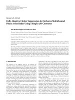
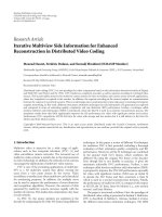
Fig. 3.
The decoder of the proposal architecture
codewords: 000, 001, 010, 011, 100, 101, 110, 111. This space
of codewords of X is partitioned into four sets, each containing
two codewords, namely, Coset1 ([0 0 0] and [1 1 1]), Coset2
([0 0 1] and [1 1 0]), Coset3 ([0 1 0] and [1 0 1]) and
Coset4 ([1 0 0] and [0 1 1]). The encoder for X identifies
the set containing the codeword for X, and sends the index
for the set (which can be described in 2 bits), also called
syndrome, instead of the individual codeword. The decoder,
in turn, on the reception of the coset index (syndrome), uses
Y to disambiguate the correct X from the set by declaring
the codeword that is closest to Y as the answer. Note that
the distance between X and Y is at most 1, and the distance
between the two codewords in any set is 3. Hence, decoding
can be done perfectly.
Cyclic Redundancy Code: The Cyclic Redundancy Code
(CRC) module has the objective to generate a binary signature
with the strength to validate the decoded block, thus selecting
the good side information candidate. There may be many side
information candidates and with the purpose of detecting the
rightly decoded block, a CRC checksum is sent to the decoder.
The CRC is designed to detect accidental changes in data,
typically small differences between two codewords provoked
by channel errors. As all the side information candidates
are somehow correlated with the coded block, the decoded
candidates are erroneous versions of that block. So, the CRC is
an excellent way to detect the side information candidate that
is decoded without errors, generating a successful decoding.
There are a wide variety of available CRC codes with different
lengths and error detection capabilities. In literature, it was
determined that a 16 bits CRC (CRC-16) has a reasonable performance for the detection of successful decoding in a PRISM
like DVC architecture. In this work, generation polynomial of
CRC-16 is shown as (2).
x16 + x12 + x5 + 1
(2)
B. Decoding process
The decoding process is performed in the following steps.
Motion Search: The motion search module has the objective of providing a motion compensated version of the current
block to the syndrome decoder. In fact, this module has to
generate the side information candidates that jointly with the
received syndrome will lead to a successful block decoding.
The decoder searches the side information in a 16 x 16 window
around the current block and sends this side information to the
syndrome decoder.
Syndrome decoder: This module has the responsibility of
selecting the quantized codewords within the cosets while
2016 International Conference on Advanced Technologies for Communications (ATC)
TABLE I.
exploiting the side information sent from the above motion
search module. Based on coset index, syndrome decoder finds
within the coset the codeword which is nearest with the side
information. This decoded block is sent to hash check module
to verify further.
Hash check: Since for every candidate predictor, we will
decode one codeword sequence from the set of sequences
labeled by the syndrome that is nearest to it, the hash signature
mechanism is required to infer the codeword sequence intended
by the encoder. For each candidate predictor we check, if it
matches the transmitted hash then the decoding is declared to
be successful. Else using the motion search module, the next
candidate predictor is obtained and then the whole procedure
repeated.
Reconstruction: This module has the purpose of attributing
a DCT value to each quantized coefficient, thus regenerating/reconstructing the source with an approximate version of
the encoded DCT coefficients block.
Inverse Transform: Once all the transform coefficients have
been dequantized, the zig-zag scan operation carried out at the
encoder is inverted to obtain a 2-D block of reconstructed
coefficients. The transformed coefficients are then inverted
using the inverse transform so as to give reconstructed pixels.
IV.
Block size
4x4
8x8
ABS
TABLE II.
Block size
4x4
8x8
ABS
AVERAGE PSNR
Akiyo
38.86
38.75
38.92
OF VIDEO TEST SEQUENCES
Container
40.94
40.81
40.96
Carphone
36.14
36.01
36.20
AVERAGE NUMBER
Akiyo
101376
82368
93012
Container
101376
82368
91112
Foreman
37.55
37.31
37.41
OF BIT IN A FRAME
Carphone
101376
82368
95343
Foreman
101376
82368
94131
sucessful decoding, the selected size of block at encoder is
important because this step defines the number of coset index
in syndrome coding. Because the LSB bits of each pixel is
decoded from coset indexes at the decoder. Thus, if the number
of coset indexes is high, the ability of error in syndrome
decoding is high and vice versa.
In the proposed method, the selection of block size is
proposed to adapt with MAD of frames in video sequences.
The changing block size at encoder helps to adjust the number
of coset indexes and thus to reduces of errors in syndrome
decoding at the decoder. The proposed method showed effectiveness in term of PSNR and total coding bit by using adaptive
block size compared to method using constant block size.
R ESULTS AND D ISCUSSIONS
In this experiment, performance of the proposed method
(Adaptive Block Size - ABS) is compared to the method with
fixed block size in [10]. The QCIF format video sequences
used in the experiment include Akiyo, Container, Foreman and
Carphone. Each sequence is tested with 100 frames.
Table 1 shows the average PSNR and total number of bit to
encode video sequences. The simulation results show that the
average PSNR of proposed method is higher than PSNR of the
method 8x8 and PSNR of the method 4x4 in some cases with
low motion like Akyioo and Container video sequences. The
reason is that the method 8x8 has 64 coset indexes. Thus, at
the decoder, the sucessful decoding is lower than the adaptive
method and method 4x4.
R EFERENCES
[1]
D. Slepian and J. Wolf, Noiseless Coding of Correlated Information
Sources, IEEE Transactions on Information Theory, vol. 19, no. 4, pp.
471-480, July 1973.
[2]
A. Wyner and J. Ziv, The Rate-Distortion Function for Source Coding
with Side Information at the Decoder, IEEE Transactions on Information
Theory, vol. 22, no. 1, pp.1-10, January 1976.
[3]
A. Aaron, R. Zhang, and B. Girod, Wyner-Ziv coding of motion video,
36th Asilomar Conference on Signals, Systems and Computers, 2002.
In Table 2, the average bit number of the proposed method
is always lower than method 4x4 and higher than method 8x8.
In the method 4x4, the number of block is the highest and
constant for video sequences because the number of blocks
is constant in each frame. Thus, the number of LSB bit and
MSB bit are consummed to encode the blocks in this method is
highest. In the method 8x8, the number of blocks is the lowest
and thus the encoding bit is lowest. By using the adaptive block
size in the proposed method, although the number of encoding
bit is not lowest, the PSNR of the proposed method is higher
compared to the other methods.
Figure 4 shows the PSNR of frame 30th in Akiyo video
sequence. The results shows that the aproach based on the
adaptive block size in the proposed method achieved higher
PSNR value while the total encoding is lower than that of
method with block size 4x4.
V.
C ONCLUSION
In DVC architecture, SI creation is one of important steps
to improve the performance of codec. To have exact SI for
342
Fig. 4.
PSNR of frame 30th in Akiyo video sequences
2016 International Conference on Advanced Technologies for Communications (ATC)
[4]
[5]
[6]
[7]
[8]
[9]
[10]
J. Ascenso, C. Brites, and F. Pereira, Improving frame interpolation with
spatial motion smoothing for pixel domain distributed video coding, 5th
EURASIP Conference on Speech and Image Processing, Multimedia
Communications and Services, 2005.
L. Natrio, C. Brites, J. Ascenso, and F. Pereira, Side information extrapolation for low-delay pixel-domain distributed video coding, International
Workshop on Very Low Bitrate Video, 2005.
A. Aaron and B. Girod, , Wyner-Ziv video coding with low-encoder
complexity, Picture Coding Symposium, 2004.
R. Puri and K. Ramchandran, PRISM: A new robust video coding
architecture based on distributed compression principles, 40th Allerton
Conf. Communication, Control and Computing,, Allerton, IL, USA,
2002.
A. Aaron, R. Zhang, and B. Girod, Wyner-Ziv Coding of Motion Video,
in Asilomar Conference on Signals, Systems, and Computers (ACSSC),
Pacific Grove, CA, USA, November 2002.
R. Puri, A. Majumdar, and K. Ramchandran, PRISM: a video coding
paradigm with motion estimation at the decoder, IEEE Transactions on
Image Processing, vol. 16, no. 10, pp. 2436-2448, Oct. 2007.
S. Milani and G, Calvagno, A Distributed Video Coder Based on
the H.264/AVC Standard, 15th European Signal Processing Conference,
Poznan, pp.673-677, Poland, 2007.
343