DSpace at VNU: Determination of User’s Position Using QZSS GPS Data
Bạn đang xem bản rút gọn của tài liệu. Xem và tải ngay bản đầy đủ của tài liệu tại đây (482.93 KB, 8 trang )
VNU Journal of Science: Mathematics – Physics, Vol. 32, No. 3 (2016) 11-18
Determination of User’s Position Using QZSS/GPS Data
Le Tien Dung*
Vietnam National Satellite Center(VNSC), Vietnam Academy of Science and Technology (VAST),
18 Hoang Quoc Viet, Cau Giay, Hanoi, Vietnam
Received 24 June 2016
Revised 25 August 2016; Accepted 09 September 2016
Abstract: This paper presents study results of standalone positioning, based on GPS/QZSS
observations. For this purpose C1 code observations from STK2 station (IGS station in Japan)
were used. Computations in RTKLIB software (RTKPOST module) were executed and SPP
method was used to position estimation. In the paper two experiments were realized: firstly user’s
position was estimated based on GPS observations, and in the second case QZSS observations
were applied also. Preliminary results of positioning accuracy show that GPS/QZSS solution
improve accuracy of X coordinate about 0.398 m, accuracy of Y coordinate about 0.432 m and
accuracy of Z coordinate about 0.285 m, respectively. Additionally RMS-3D error was estimated
based on coordinate differences from GPS and GPS/QZSS solutions. Average value of RMS-3D
term equals to 0.986 m, with magnitude order between 0.003 m and 3.649 m.
Keywords: GPS, SPP Method. QZSS-Zenith
1. Introduction
Quasi-Zenith Satellite System (QZSS-Zenith) is a regional positioning system which was built by
Satellite Positioning Research and Application Center – SPAC, foundation of Japanese Government
[1]. In primary conceptions, QZSS system had assured coverage over Eastern Asia and Australia with
Oceania. The MGEX campaign underlines possibility of utilization QZSS signals also in Central
Europe [2]. Major principles of the system were development around to 3 functions: positioning
accuracy improvement, positioning available time improvement, and transmit short information about
emergency warnings, such as disaster or crisis time [3-5]. QZSS system divides into 3 components:
Space Segment (SS), Ground Segment (GS) and User Segment (US). In 2014, Space Segment consist
of only one satellite Michibiki, which was launched in 2010 [6, 7]. Orbital plan of Michibiki satellite
is similar to number “eight” with inclination angle more than 43 degree and orbital radius about 42
164 km [5, 8]. Full constellation of QZSS system will include 3 satellites, located on the
geosynchronous orbit IGSO. In future plan, 4 satellites from geostationary orbit (GEO) will be added
to rest constellation [9]. Ground Segment contains 4 type of stations [10, 11]:
_______
Tel.: 84-975996610
Email:
11
12
L.T. Dung / VNU Journal of Science: Mathematics – Physics, Vol. 32, No. 3 (2016) 11-18
- Master Control Station (estimation orbit parameters and clock offset, generation broadcast
ephemeris, introduction orbit correction)
- Monitor Station (received and distributed QZSS observations)
- Tracking Station (upload navigation massege and monitor satellites status)
- Time Management Station (determination time transfer). Stations number of Ground Segment
equal to 10 and they are located in the Japan (5 stations), in the USA (2 stations), in the India (1
station), in the Australia (1 station), in the Thailand (1 station) [12]. User Segment include
multiplexing receivers, which can register and collect Multi-GNSS observations.
QZSS system has important influence in urban area in Japan, where signals from GPS or
GLONASS satellites could be reflected from high buildings, what causes problem with positioning
[13]. In article preliminary results of standalone positioning in urban region were presented. Reference
data from Shintotsukawa city (Hokkaido island) were used to computations and processing of
GPS/QZSS observations were implemented in RTKLIB software. Single Point Positioning (SPP)
method was used for determination receiver coordinates.
2. Methematical Model for Position Estimation
Basic equation to determination of user’s position, based on GPS/QZSS observations, is given
by [14]:
(1)
where:
C1GPS, C1QZSS – code observations in GPS and QZSS system
ρGPS, ρQZSS – geometric range between satellite (GPS/QZSS) and receiver
C – speed light
dtsGPS, dtsQZSS – satellite clock offset (GPS/QZSS)
dtrGPS, dtrQZSS – receiver clock offset (GPS/QZSS)
IGPS, IQZSS – ionosphere delay in GPS and QZSS system
TGPS, TQZSS – troposphere delay in GPS and QZSS system
RelGPS, RelQZSS – relativistic effect in GPS and QZSS system
TGDGPS, TGDQZSS – transmitter group delay in GPS and QZSS system [12, 15]
Equation (1) presents Single Point Positioning (SPP) method and it’s very popular solution,
especially in standalone positioning and navigation. The left side of equation (1) include raw
observations from RINEX file and they are expressed in meter unit. Whereas the right side,
measurements models and unknown parameters are described. Usually measurements models
represent group of systematic errors such as: satellite clock bias, ionosphere and troposphere delay,
relativistic effect and instrumental biases. Rest terms in equation (1) are called unknown parameters
and contain correction to geocentric coordinates XYZ (3 parameters) and receiver clock bias (one
parameter). In case of hybrid data (see equation 1), number of estimated parameters will be 5
(additionally unknown parameter is a receiver clock in QZSS system).
Least square method is applied to solve the equation (1) and reads as follows [16]:
L.T. Dung / VNU Journal of Science: Mathematics – Physics, Vol. 32, No. 3 (2016) 11-18
13
(2)
where:
A – matrix of coefficients; matrix with dimension (n, k)
n – number of observations,
k – number of unknown parameters, dx – vector with unknown parameters, l – vector of
observations
v – vector of residuals
Vector δx with unknown parameters is estimated from normal equations, as below [17]:
(3)
Mean errors for unknown parameters are solved based on equation (4) [18]:
(4)
where:
m0 – standard error of unit weight
Equations (3) and (4) should be applied for each measure-ments epoch from RINEX file in
iterative scheme. If unknown parameters from equation (3) will be estimated then user’s position must
also be corrected. The mx term in equation (4) expresses accuracy for unknown parameters.
3. Experiments and results
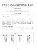
Analysis was based on 24 hours (with interval 30 seconds) GPS/QZSS data from STK2 station in
RINEX format 3.00. STK2 reference station (see Fig. 1) is located in Shintotsukawa (Hokkaido
island) in north Japan (coordinate: 43.52 N, 141.84 E). Station has dual frequency receiver TRIMBLE
NETR9 (version 4.61), which makes enable to tracking GPS, GLONASS and QZSS satellites.
Receiver TRIMBLE NETR9 is a part of IGS service, and more information about station are available
on the website [19]. RINEX data and broadcast ephemeris (GPS and QZSS) to calculations, for day 4
October 2014, were downloaded from BKG server [20]. RTKPOST module in RTKLIB software [21]
was utilized in computations processing.
Fig. 1. The STK2 site in Japan.
14
L.T. Dung / VNU Journal of Science: Mathematics – Physics, Vol. 32, No. 3 (2016) 11-18
The main options in code source of RTKPOST module was configured and applied, as below:
- RINEX file type: RINEX 3.00
- source of GPS/QZSS ephemeris data: Broadcast Ephemeris
- method of satellite position determination: based on Broadcast Ephemeris
- Earth rotation correction: applied
- source of GPS/QZSS satellite clock data: Broadcast Ephemeris
- method of satellite clock determination: interpolation using 2-degree polynomial
- ionosphere delay: Klobuchar model
- source of coefficients in Klobuchar model: GPS/QZSS navigation message
- troposphere delay: Saastamoinen model
- instrumental biases: TGD applied (based on Broadcast Ephe-meris)
- satellite phase center offset/variation: not applied
- receiver phase center offset/variation: not applied
- multipath effect: not applied
- positioning mode: single
- processing mode: static
- basic observations: C1 code
- mathematical model of user’s position determination: least square estimation
- weight matrix of measurements: not implemented for SPP method in RTKLIB
- cut off elevation: 10°
- reference frame: WGS-84
- number of unknown parameters: k = 4 or k = 5
- number of observations: n > 4
- approximately coordinates of user’s position: based on RINEX file
- output solution of coordinates: XYZ in geocentric frame
- receiver clock: estimated parameter
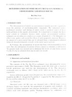
Fig. 2. Mean errors of X coordinate.
L.T. Dung / VNU Journal of Science: Mathematics – Physics, Vol. 32, No. 3 (2016) 11-18
15
In submitted paper two experiments were realized. In the first test, user’s position was estimated
based on only GPS observations and in second case, receiver coordinates were calculated using
GPS/QZSS data. Mean errors from both solutions were compared and visualized into Fig. 2 and 4.
Measurement epochs (about 1000) without QZSS observations were removed from comparison
processing. Fig. 2 presents results of positioning accuracy for X coordinate.
Magnitude of mean errors for GPS solution are between 2.531 m and 13.510 m, for GPS/QZSS
solution are between 2.523 m and 13.103 m, respectively. Generally average value of mean errors for
each solutions equals to 6.019 m and 5.621 m, respectively. Mean difference of accuracy between
GPS and GPS/QZSS solution for X coordinate amounts to 0.398 m with standard deviation 0.264 m.
Based on Fig. 2, mean errors of X component are lower for GPS/QZSS solution than GPS solution.
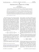
Fig. 3. Mean errors of Y coordinate.
Fig. 4. Mean errors of Z coordinate.
16
L.T. Dung / VNU Journal of Science: Mathematics – Physics, Vol. 32, No. 3 (2016) 11-18
Fig. 3 shows positioning accuracy results for Y coordinate. Based on Fig. 3, mean errors of Y term
are similar for GPS/ QZSS and GPS solutions. Maximum and minimum values of mean errors for both
solutions are about 2.014 m and 10.856 m, adequately. Average value of accuracy for both solutions
equals to 4.769 m and 4.337 m, respectively. Mean difference of accuracy between GPS and
GPS/QZSS solution for Y coor-dinate amounts to 0.432 m with standard deviation 0.303 m. Influence
of QZSS observations for determination accuracy of Y coordinate is on the same accuracy level like X
coordinate.
Fig. 4 presents positioning accuracy results for Z coordi-nate. Magnitude order of accuracy for
GPS and GPS/QZSS solutions is between 2.215 m and 19.310 m. Average value of accuracy for both
solutions is about 6.131 m and 5.845 m, respectively. Difference of accuracy between GPS and GPS/
QZSS solution for Z coordinate amounts to 0.285 m with stan-dard deviation 0.349 m.
Relation between mean errors from both solutions can be expressed, as below:
(5)
where:
qx, qy, qz – correlation coefficients between mean errors for GPS and GPS/QZSS solutions
MxGPS, MxGPS/QZSS – mean errors of X coordinates for both solutions (see Fig. 2)
MyGPS, MyGPS/QZSS – mean errors of Y coordinates for both solutions (see Fig. 3)
MzGPS, MzGPS/QZSS – mean errors of Z coordinates for both solutions (see Fig. 4)
Table. 1. Results of correlation coefficients for mean errors Mx, My, and Mz
Index of parameter
qx
qy
qz
Average value
0.938
0.913
0.953
Table. 1 presents results of correlations coefficients between mean errors for GPS and GPS/QZSS
solutions. The qx term equals to 0.938, that is the reason that solution GPS/QZSS improved accuracy
of X coordinate more than 6 %. In case of qy coefficient, GPS/QZSS solution decreased mean errors
of Y coordinate close to 9 %. Influence of GPS/QZSS solution on the Z coordinate can reduced mean
errors only to 5 % (see qz term). In connection with it, GPS/QZSS solution has got a little impact for
accuracy improvement of Z coordinate. Additionally, mean errors Mz are large in comparison to mean
errors Mx and My.
The RMS-3D factor was also obtained in positioning accu-racy analysis. The equation of RMS-3D
index can be described, as follows:
(6)
L.T. Dung / VNU Journal of Science: Mathematics – Physics, Vol. 32, No. 3 (2016) 11-18
17
where
∆X = XGPS/QZSS - XGPS - difference between X coordinates from GPS and GPS/QZSS solutions
ΔY = YGPS/QZSS - YGPS - difference between Y coordinates from GPS and GPS/QZSS solutions
ΔZ = ZGPS/QZSS - ZGPS - difference between Z coordinates from GPS and GPS/QZSS solutions.
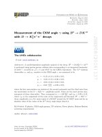
Fig. 5. Results of RMS-3D error.
Fig. 5 shows RMS-3D results based on XYZ coordinates from GPS and GPS/QZSS solutions.
Based on Fig. 5, average value of RMS-3D error amounts to 0.986 m, with magnitude between 0.003
m and 3.649 m. More than 57 % results of RMS-3D errors are less than 1 m, but about 90 % results of
RMS-3D errors are less than 2 m. Trend of RMS-3D errors is very irregularity and includes 2
anomalies: between epochs 400−500, and 1700−1800. In these cases, mean errors of XYZ coordinates
(see Fig. 2, 3 and 4) are changed diametrically and they are started to raise up. This situation is very
negative, especially for coordinates values, because RMS-3D can reach up more than 3.5 m. Similar
phenomena can be seeing in behavior of mean errors of each coordinates into Fig. 2, 3 and 4.
4. Conclusions
Results of standalone positioning using GPS/QZSS data were presented in article. Example code
observations were taken from RINEX 3.00 file from STK2 station in Japan. Computations were
executed in RTKLIB software (RTKPOST module) using SPP method. The receiver coordinates were
solved twice: in first test only GPS observations were used, but in second case QZSS data were also
applied. Preliminary results show that GPS/QZSS solution improve accuracy of X coordinate about
0.398 m, accuracy of Y coordinate about 0.432 m and accuracy of Z coordinate about 0.285 m,
respectively. Moreover correlation coefficients were obtained for mean errors of XYZ coordinates
from each solutions. Generally GPS/QZSS solution increased accuracy of each coordinates between 5
% to 9 %. The RMS-3D errors between XYZ coordinates from GPS and GPS/QZSS solutions were
estimated also. Average bias of RMS-3D parameters is about 0.986 m, with magnitude order between
0.003 m and 3.649 m.
Acknowledgements
The author would like to acknowledge BKG Service for making available RINEX data, Mr.
Takasu for making available RTKLIB software and VNSC (Vietnam National Satellite Center) for
supporting.
18
L.T. Dung / VNU Journal of Science: Mathematics – Physics, Vol. 32, No. 3 (2016) 11-18
References
[1] Matsuoka S., Service status of QZSS, The Asia Pacific Regional Space Agency Forum, Communication
Satellite Application WG, 2008.
[2] www.igs.org/mgex
[3] Aoki M., QZSS The Japanese Quasi-Zenith Satellite System: Program Updates and Current status, 15th
International Committee on GNSS, Torino 2010.
[4] Fujiwara S., QZSS and MSAS The Quasi-Zenith Satellite System and The Multi-functional Transport Satellite
Satellite-based Augmentation System, ICG-6, Tokyo 2011.
[5] Kogure S., The status of Quasi-Zenith Satellite System (QZSS)technical demonstration, United Nations
Economic and Social Commission for Asia and the Pacific (UNESCAP), Workshop on Use of MultiGlobal
Navigation Satellite Systems for Sustainable Development, Bangkok 2012.
[6] Sakai T., Fukushima S., Ito K., QZSS L1-SAIF Initial Experiment Results, ION ITM, San Diego 2011.
[7] Li Y., Rizos C., Evaluation of positioning accuracy with QZSS enhanced global navigation satellite systems,
2012, available at: [www.gmat.unsw.edu.au/snap/publications/liy&rizos2012a.pdf].
[8] Yoshitomi S., GNSS Augmentation using Quasi-Zenith Satellite System (QZSS) and its benefits for satellite
navigation applications, 10th Meeting of the APEC Global Navigation Satellite system (GNSS), Implementation
Team (GIT/10), Philippines, 2006.
[9] Takasu T., Ebinuma T., Yasuda A., Effect of Quasi Zenith Satellite (QZS) on GPS Positioning, 2009, retrieved
from [ />[10] JAXA, Impact of SLR tracking on QZSS, ILRS Workshop, Metsovo 2009.
[11] JAXA, Interface Specification for QZSS (IS-QZSS), version 1.5, 2013.
[12] JAXA, Interface Specification for QZSS (IS-QZSS), version 1.6, 2014.
[13] Angrisano A., Pacifico A., Vultaggio M., Augmentation satellites constellations, a simulation on EGNOS and
QZSS for Europe coverage, ENC 2008.
[14] RTKLIB ver. 2.4.2.
[15] Spits J., Total Electron Content reconstruction using triple frequency GNSS signals, Dissertation thesis,
Universitè de Liège, Belgium, 2011.
[16] Takasu T., RTKLIB ver. 2.4.2 Manual, 2013.
[17] Sanz Subirana J., Juan Zornoza J. M., Hernández-Pajares M., GNSS DATA PROCESSING, Volume I:
Fundamentals and Algorithms, ESA, 2013.
[18] Angrisano A., GNSS/INS Integration Methods, Dissertation Thesis, Napoli 2010.
[19] />[20] />[21] www.rtklib.com