Tài Liệu - Võ Tấn Dũng (votandung) CCNA Security Labs
Bạn đang xem bản rút gọn của tài liệu. Xem và tải ngay bản đầy đủ của tài liệu tại đây (528.57 KB, 54 trang )
CCNA Security 1.0.1
Instructor Packet Tracer Manual
This document is exclusive property of Cisco Systems, Inc. Permission is granted
to print and copy this document for non-commercial distribution and exclusive
use by instructors in the CCNA Security course as part of an official Cisco
Networking Academy Program.
PT Activity: Configure Cisco Routers for Syslog, NTP, and SSH
Operations
Instructor Version
Topology Diagram
Addressing Table
Device
R1
Interface
IP Address
Subnet Mask
Default Gateway
Switch Port
FA0/1
192.168.1.1
255.255.255.0
N/A
S1 FA0/5
S0/0/0 (DCE)
10.1.1.1
255.255.255.252
N/A
N/A
S0/0/0
10.1.1.2
255.255.255.252
N/A
N/A
S0/0/1 (DCE)
10.2.2.2
255.255.255.252
N/A
N/A
FA0/1
192.168.3.1
255.255.255.0
N/A
S3 FA0/5
S0/0/1
10.2.2.1
255.255.255.252
N/A
N/A
PC-A
NIC
192.168.1.5
255.255.255.0
192.168.1.1
S1 FA0/6
PC-B
NIC
192.168.1.6
255.255.255.0
192.168.1.1
S2 FA0/18
PC-C
NIC
192.168.3.5
255.255.255.0
192.168.3.1
S3 FA0/6
R2
R3
All contents are Copyright © 1992–2010 Cisco Systems, Inc. All rights reserved. This document is Cisco Public Information.
Page 1 of 5
CCNA Security
Learning Objectives
•
Configure routers as NTP clients.
•
Configure routers to update the hardware clock using NTP.
•
Configure routers to log messages to the syslog server.
•
Configure routers to timestamp log messages.
•
Configure local users.
•
Configure VTY lines to accept SSH connections only.
•
Configure RSA key pair on SSH server.
•
Verify SSH connectivity from PC client and router client.
Introduction
The network topology shows three routers. You will configure NTP and Syslog on all routers. You will configure
SSH on R3.
Network Time Protocol (NTP) allows routers on the network to synchronize their time settings with an NTP
server. A group of NTP clients that obtain time and date information from a single source have more consistent
time settings and Syslog messages generated can be analyzed more easily. This can help when
troubleshooting issues with network problems and attacks. When NTP is implemented in the network, it can be
set up to synchronize to a private master clock, or to a publicly available NTP server on the Internet.
The NTP Server is the master NTP server in this lab. You will configure the routers to allow the software clock
to be synchronized by NTP to the time server. Also, you will configure the routers to periodically update the
hardware clock with the time learned from NTP. Otherwise, the hardware clock will tend to gradually lose or
gain time (drift) and the software clock and hardware clock may become out of synchronization with each other.
The Syslog Server will provide message logging in this lab. You will configure the routers to identify the remote
host (Syslog server) that will receive logging messages.
You will need to configure timestamp service for logging on the routers. Displaying the correct time and date in
Syslog messages is vital when using Syslog to monitor a network. If the correct time and date of a message is
not known, it can be difficult to determine what network event caused the message.
R2 is an ISP connected to two remote networks: R1 and R3. The local administrator at R3 can perform most
router configurations and troubleshooting; however, since R3 is a managed router, the ISP needs access to R3
for occasional troubleshooting or updates. To provide this access in a secure manner, the administrators have
agreed to use Secure Shell (SSH).
You use the CLI to configure the router to be managed securely using SSH instead of Telnet. SSH is a network
protocol that establishes a secure terminal emulation connection to a router or other networking device. SSH
encrypts all information that passes over the network link and provides authentication of the remote computer.
SSH is rapidly replacing Telnet as the remote login tool of choice for network professionals.
The servers have been pre-configured for NTP and Syslog services respectively. NTP will not require
authentication. The routers have been pre-configured with the following:
•
Enable password: ciscoenpa55
•
Password for vty lines: ciscovtypa55
•
Static routing
All contents are Copyright © 1992–2010 Cisco Systems, Inc. All rights reserved. This document is Cisco Public Information.
Page 2 of 5
CCNA Security
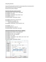
Task 1:
S tep 1.
Configure routers as NTP Clients.
T es t C onnec tivity
•
Ping from PC-C to R3.
•
Ping from R2 to R3.
•
Telnet from PC-C to R3. Exit the Telnet session.
•
Telnet from R2 to R3. Exit the Telnet session.
S tep 2.
C onfigure R 1, R 2 and R 3 as NT P c lients .
R1(config)# ntp server 192.168.1.5
R2(config)# ntp server 192.168.1.5
R3(config)# ntp server 192.168.1.5
Verify client configuration using the command show ntp status.
S tep 3.
C onfigure routers to update hardware c loc k.
Configure R1, R2 and R3 to periodically update the hardware clock with the time learned from NTP.
R1(config)# ntp update-calendar
R2(config)# ntp update-calendar
R3(config)# ntp update-calendar
Verify that the hardware clock was updated using the command show clock.
S tep 4.
C onfigure routers to times tamp log mes s ages .
Configure timestamp service for logging on the routers. S tep 0.
R1(config)# service timestamps log datetime msec
R2(config)# service timestamps log datetime msec
R3(config)# service timestamps log datetime msec
Task 2:
S tep 1.
Configure routers to log messages to the Syslog Server.
C onfigure the routers to identify the remote hos t (S ys log S erver) that will rec eive logging
mes s ages .
R1(config)# logging host 192.168.1.6
R2(config)# logging host 192.168.1.6
R3(config)# logging host 192.168.1.6
The router console will display a message that logging has started.
S tep 2.
V erify logging c onfiguration us ing the c ommand s how logging.
S tep 3.
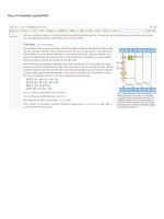
E xamine logs of the S ys log s erver. S tep 0.
From the Config tab of the Syslog server’s dialogue box, select the Syslog services button. Observe the
logging messages received from the routers.
Note:
Log messages can be generated on the server by executing commands on the router. For example,
entering and exiting global configuration mode will generate an informational configuration message.
All contents are Copyright © 1992–2010 Cisco Systems, Inc. All rights reserved. This document is Cisco Public Information.
Page 3 of 5
CCNA Security
Task 3:
S tep 1.
Configure R3 to support SSH connections.
C onfigure a domain name.
Configure a domain name of ccnasecurity.com on R3.
R3(config)# ip domain-name ccnasecurity.com
S tep 2.
C onfigure us ers for login from the S S H c lient on R 3.
Create a user ID of SSHadmin with the highest possible privilege level and a secret password of
ciscosshpa55.
R3(config)# username SSHadmin privilege 15 secret ciscosshpa55
S tep 3.
C onfigure the inc oming V T Y lines on R 3.
Use the local user accounts for mandatory login and validation. Accept only SSH connections.
R3(config)# line vty 0 4
R3(config-line)# login local
R3(config-line)# transport input ssh
S tep 4.
E ras e exis ting key pairs on R 3.
Any existing RSA key pairs should be erased on the router.
R3(config)#crypto key zeroize rsa
Note:
S tep 5.
If no keys exist, you might receive this message: % No Signature RSA Keys found in
configuration.
G enerate the R S A enc ryption key pair for R 3.
The router uses the RSA key pair for authentication and encryption of transmitted SSH data. Configure the RSA
keys with a modulus of 1024. The default is 512, and the range is from 360 to 2048.
R3(config)# crypto key generate rsa [Enter]
The name for the keys will be: R3.ccnasecurity.com
Choose the size of the key modulus in the range of 360 to 2048 for your
General Purpose Keys. Choosing a key modulus greater than 512 may take
a few minutes.
How many bits in the modulus [512]:1024
% Generating 1024 bit RSA keys, keys will be non-exportable...[OK]
Note:
S tep 6.
The command to generate RSA encryption key pairs for R3 in Packet Tracer differs from those used in
the lab.
V erify the S S H c onfiguration.
Use the show ip ssh command to see the current settings. Verify that the authentication timeout and retries
are at their default values of 120 and 3.
S tep 7.
C onfigure S S H timeouts and authentic ation parameters .
The default SSH timeouts and authentication parameters can be altered to be more restrictive. Set the timeout
to 90 seconds, the number of authentication retries to 2, and the version to 2.
R3(config)# ip ssh time-out 90
R3(config)# ip ssh authentication-retries 2
R3(config)# ip ssh version 2
Issue the show ip ssh command again to confirm that the values have been changed.
All contents are Copyright © 1992–2010 Cisco Systems, Inc. All rights reserved. This document is Cisco Public Information.
Page 4 of 5
CCNA Security
S tep 8.
Attempt to c onnec t to R 3 via T elnet from P C -C .
Open the Desktop of PC-C. Select the Command Prompt icon. From PC-C, enter the command to connect to
R3 via Telnet.
PC> telnet 192.168.3.1
This connection should fail, since R3 has been configured to accept only SSH connections on the virtual
terminal lines.
S tep 9.
C onnec t to R 3 us ing S S H on P C -C .
Open the Desktop of PC-C. Select the Command Prompt icon. From PC-C, enter the command to connect to
R3 via SSH. When prompted for the password, enter the password configured for the administrator
ciscosshpa55.
PC> ssh –l SSHadmin 192.168.3.1
S tep 10. C onnec t to R 3 us ing S S H on R 2.
In order to troubleshoot and maintain the R3 router, the administrator at the ISP must use SSH to access the
router CLI. From the CLI of R2, enter the command to connect to R3 via SSH version 2 using the SSHadmin
user account. When prompted for the password, enter the password configured for the administrator:
ciscosshpa55.
R2# ssh –v 2 –l SSHadmin 10.2.2.1
S tep 11. C hec k res ults .
Your completion percentage should be 100%. Click Check Results to see feedback and verification of which
required components have been completed.
All contents are Copyright © 1992–2010 Cisco Systems, Inc. All rights reserved. This document is Cisco Public Information.
Page 5 of 5
PT Activity: Configure AAA Authentication on Cisco Routers
Instructor Version
Topology Diagram
Addressing Table
Device
Interface
IP Address
Subnet Mask
Fa0/0
192.168.1.1
255.255.255.0
S0/0/0
10.1.1.2
255.255.255.252
S0/0/0
10.1.1.1
255.255.255.252
Fa0/0
192.168.2.1
255.255.255.0
S0/0/1
10.2.2.1
255.255.255.252
S0/0/1
10.2.2.2
255.255.255.252
Fa0/0
192.168.3.1
255.255.255.0
TACACS+ Server
NIC
192.168.2.2
255.255.255.0
RADIUS Server
NIC
192.168.3.2
255.255.255.0
PC-A
NIC
192.168.1.3
255.255.255.0
PC-B
NIC
192.168.2.3
255.255.255.0
PC-C
NIC
192.168.3.3
255.255.255.0
R1
R2
R3
All contents are Copyright © 1992–2010 Cisco Systems, Inc. All rights reserved. This document is Cisco Public Information.
Page 1 of 5
CCNA Security
Learning Objectives
•
Configure a local user account on R1 and authenticate on the console and VTY lines using local AAA.
•
Verify local AAA authentication from the R1 console and the PC-A client.
•
Configure a server-based AAA authentication using TACACS+.
•
Verify server-based AAA authentication from PC-B client.
•
Configure a server-based AAA authentication using RADIUS.
•
Verify server-based AAA authentication from PC-C client.
Introduction
The network topology shows routers R1, R2 and R3. Currently all administrative security is based on knowledge
of the enable secret password. Your task is to configure and test local and server-based AAA solutions.
You will create a local user account and configure local AAA on router R1 to test the console and VTY logins.
•
User account: Admin1 and password admin1pa55
You will then configure router R2 to support server-based authentication using the TACACS+ protocol. The
TACACS+ server has been pre-configured with the following:
•
Client: R2 using the keyword tacacspa55
•
User account: Admin2 and password admin2pa55
Finally, you will configure router R3 to support server-based authentication using the RADIUS protocol. The
RADIUS server has been pre-configured with the following:
•
Client: R3 using the keyword radiuspa55
•
User account: Admin3 and password admin3pa55
The routers have also been pre-configured with the following:
•
Enable secret password: ciscoenpa55
•
RIP version 2
Note: The console and VTY lines have not been pre-configured.
Task 1:
S tep 1.
Configure Local AAA Authentication for Console Access on R1
T es t c onnec tivity.
•
Ping from PC-A to PC-B.
•
Ping from PC-A to PC-C.
•
Ping from PC-B to PC-C.
S tep 2.
C onfigure a loc al us ername on R 1.
Configure a username of Admin1 and secret password of admin1pa55.
R1(config)# username Admin1 password admin1pa55
S tep 3.
C onfigure loc al AA A authentic ation for c ons ole ac c es s on R 1.
Enable AAA on R1 and configure AAA authentication for console login to use the local database.
R1(config)# aaa new-model
R1(config)# aaa authentication login default local
All contents are Copyright © 1992–2010 Cisco Systems, Inc. All rights reserved. This document is Cisco Public Information.
Page 2 of 5
CCNA Security
S tep 4.
C onfigure the line c ons ole to us e the defined AA A authentic ation method.
Enable AAA on R1 and configure AAA authentication for console login to use the default method list.
R1(config)# line console 0
R1(config-line)# login authentication default
S tep 5.
V erify the AA A authentic ation method.
Verify the user EXEC login using the local database.
R1(config-line)# end
%SYS-5-CONFIG_I: Configured from console by console
R1# exit
R1 con0 is now available
Press RETURN to get started.
************ AUTHORIZED ACCESS ONLY *************
UNAUTHORIZED ACCESS TO THIS DEVICE IS PROHIBITED.
User Access Verification
Username: Admin1
Password: admin1pa55
R1>
Task 2:
S tep 1.
Configure Local AAA Authentication for VTY Lines on R1
C onfigure a named lis t AA A authentic ation method for V T Y lines on R 1.
Configure a named list called TELNET-LOGIN to authenticate logins using local AAA.
R1(config)# aaa authentication login TELNET-LOGIN local
S tep 2.
C onfigure the V T Y lines to us e the defined AA A authentic ation method.
Configure the VTY lines to use the named AAA method.
R1(config)# line vty 0 4
R1(config-line)# login authentication TELNET-LOGIN
R1(config-line)# end
S tep 3.
V erify the AA A authentic ation method.
Verify the Telnet configuration. From the command prompt of PC-A, Telnet to R1.
PC> telnet 192.168.1.1
************ AUTHORIZED ACCESS ONLY *************
UNAUTHORIZED ACCESS TO THIS DEVICE IS PROHIBITED.
User Access Verification
Username: Admin1
Password: admin1pa55
R1>
All contents are Copyright © 1992–2010 Cisco Systems, Inc. All rights reserved. This document is Cisco Public Information.
Page 3 of 5
CCNA Security
Task 3:
S tep 1.
Configure Server-Based AAA Authentication Using TACACS+ on R2
C onfigure a bac kup loc al databas e entry c alled Admin.
For backup purposes, configure a local username of Admin and secret password of adminpa55.
R2(config)# username Admin password adminpa55
S tep 2.
V erify the T AC AC S + S erver c onfiguration.
Select the TACACS+ Server. From the Config tab, click on AAA and notice that there is a Network
configuration entry for R2 and a User Setup entry for Admin2.
S tep 3.
C onfigure the T AC AC S + s erver s pec ific s on R 2.
Configure the AAA TACACS server IP address and secret key on R2.
R2(config)# tacacs-server host 192.168.2.2
R2(config)# tacacs-server key tacacspa55
S tep 4.
C onfigure AA A login authentic ation for c ons ole ac c es s on R 2.
Enable AAA on R2 and configure all logins to authenticate using the AAA TACACS+ server and if not
available, then use the local database.
R2(config)# aaa new-model
R2(config)# aaa authentication login default group tacacs+ local
S tep 5.
C onfigure the line c ons ole to us e the defined AA A authentic ation method.
Configure AAA authentication for console login to use the default AAA authentication method.
R2(config)# line console 0
R2(config-line)# login authentication default
S tep 6.
V erify the AA A authentic ation method.
Verify the user EXEC login using the AAA TACACS+ server.
R2(config-line)# end
%SYS-5-CONFIG_I: Configured from console by console
R2# exit
R2 con0 is now available
Press RETURN to get started.
************ AUTHORIZED ACCESS ONLY *************
UNAUTHORIZED ACCESS TO THIS DEVICE IS PROHIBITED.
User Access Verification
Username: Admin2
Password: admin2pa55
R2>
All contents are Copyright © 1992–2010 Cisco Systems, Inc. All rights reserved. This document is Cisco Public Information.
Page 4 of 5
CCNA Security
Task 4:
S tep 1.
Configure Server-Based AAA Authentication Using RADIUS on R3
C onfigure a bac kup loc al databas e entry c alled Admin.
For backup purposes, configure a local username of Admin and secret password of adminpa55.
R3(config)# username Admin password adminpa55
S tep 2.
V erify the R ADIUS S erver c onfiguration.
Select the RADIUS Server. From the Config tab, click on AAA and notice that there is a Network configuration
entry for R3 and a User Setup entry for Admin3.
S tep 3.
C onfigure the R ADIUS s erver s pec ific s on R 3.
Configure the AAA RADIUS server IP address and secret key on R3.
R3(config)# radius-server host 192.168.3.2
R3(config)# radius-server key radiuspa55
S tep 4.
C onfigure AA A login authentic ation for c ons ole ac c es s on R 3.
Enable AAA on R3 and configure all logins to authenticate using the AAA RADIUS server and if not available,
then use the local database.
R3(config)# aaa new-model
R3(config)# aaa authentication login default group radius local
S tep 5.
C onfigure the line c ons ole to us e the defined AA A authentic ation method.
Configure AAA authentication for console login to use the default AAA authentication method.
R3(config)# line console 0
R3(config-line)# login authentication default
S tep 6.
V erify the AA A authentic ation method.
Verify the user EXEC login using the AAA TACACS+ server.
R3(config-line)# end
%SYS-5-CONFIG_I: Configured from console by console
R3# exit
R3 con0 is now available
Press RETURN to get started.
************ AUTHORIZED ACCESS ONLY *************
UNAUTHORIZED ACCESS TO THIS DEVICE IS PROHIBITED.
User Access Verification
Username: Admin3
Password: admin3pa55
R3>
S tep 7.
C hec k res ults .
Your completion percentage should be 100%. Click Check Results to see feedback and verification of which
required components have been completed.
All contents are Copyright © 1992–2010 Cisco Systems, Inc. All rights reserved. This document is Cisco Public Information.
Page 5 of 5
PT Activity: Configure IP ACLs to Mitigate Attacks
Instructor Version
Topology Diagram
Addressing Table
Device
Interface
IP Address
Subnet Mask
Default Gateway
Fa0/1
192.168.1.1
255.255.255.0
N/A
S0/0/0 (DCE)
10.1.1.1
255.255.255.252
N/A
S0/0/0
10.1.1.2
255.255.255.252
N/A
S0/0/1(DCE)
10.2.2.2
255.255.255.252
N/A
Lo0
192.168.2.1
255.255.255.0
N/A
Fa0/1
192.168.3.1
255.255.255.0
N/A
S0/0/1
10.2.2.1
255.255.255.252
N/A
PC-A
NIC
192.168.1.3
255.255.255.0
192.168.1.1
PC-C
NIC
192.168.3.3
255.255.255.0
192.168.3.1
R1
R2
R3
Objectives
•
Verify connectivity among devices before firewall configuration.
•
Use ACLs to ensure remote access to the routers is available only from management station PC-C.
•
Configure ACLs on R1 and R3 to mitigate attacks.
•
Verify ACL functionality.
All contents are Copyright © 1992-2010 Cisco Systems, Inc. All rights reserved. This document is Cisco Public Information.
Page 1 of 4
CCNA Security
Introduction
Access to routers R1, R2, and R3 should only be permitted from PC-C, the management station. PC-C is also
used for connectivity testing to PC-A, a server providing DNS, SMTP, FTP, and HTTPS services.
Standard operating procedure is to apply ACLs on edge routers to mitigate common threats based on source
and/or destination IP address. In this activity, you create ACLs on edge routers R1 and R3 to achieve this goal.
You then verify ACL functionality from internal and external hosts.
The routers have been pre-configured with the following:
•
Enable password: ciscoenpa55
•
Password for console: ciscoconpa55
•
Username for VTY lines: SSHadmin
•
Password for VTY lines: ciscosshpa55
•
IP addressing
•
Static routing
Task 1:
Verify Basic Network Connectivity
Verify network connectivity prior to configuring the IP ACLs.
S tep 1.
F rom the P C -C c ommand prompt, ping the P C -A s erver.
S tep 2.
F rom the P C -C c ommand prompt, S S H to the router R 2 L o0 interfac e. E xit the S S H s es s ion.
S tep 3.
F rom P C -C , open a web brows er to the P C -A s erver (us ing the IP addres s ) to dis play the web
page. C los e the brows er on P C -C .
S tep 4.
F rom the P C -A s erver c ommand prompt, ping P C -C .
Task 2:
S tep 1.
Secure Access to Routers
C onfigure AC L 10 to bloc k all remote ac c es s to the routers exc ept from P C -C .
Use the access-list command to create a numbered IP ACL on R1, R2, and R3.
R1(config)# access-list 10 permit 192.168.3.3 0.0.0.0
R2(config)# access-list 10 permit 192.168.3.3 0.0.0.0
R3(config)# access-list 10 permit 192.168.3.3 0.0.0.0
S tep 2.
Apply AC L 10 to ingres s traffic on the V T Y lines .
Use the access-class command to apply the access list to incoming traffic on the VTY lines.
R1(config-line)# access-class 10 in
R2(config-line)# access-class 10 in
R3(config-line)# access-class 10 in
S tep 3.
V erify ex c lus ive ac c es s from management s tation P C -C .
SSH to 192.168.2.1 from PC-C (should be successful). SSH to 192.168.2.1 from PC-A (should fail).
PC> ssh –l SSHadmin 192.168.2.1
All contents are Copyright © 1992–2010 Cisco Systems, Inc. All rights reserved. This document is Cisco Public Information.
Page 2 of 4
CCNA Security
Task 3:
Create a Numbered IP ACL 100
On R3, block all packets containing the source IP address from the following pool of addresses: 127.0.0.0/8,
any RFC 1918 private addresses, and any IP multicast address.
S tep 1.
C onfigure AC L 100 to bloc k all s pec ified traffic from the outs ide network.
You should also block traffic sourced from your own internal address space if it is not an RFC 1918 address (in
this activity, your internal address space is part of the private address space specified in RFC 1918).
Use the access-list command to create a numbered IP ACL.
R3(config)#
R3(config)#
R3(config)#
R3(config)#
R3(config)#
R3(config)#
S tep 2.
access-list
access-list
access-list
access-list
access-list
access-list
100
100
100
100
100
100
deny ip 10.0.0.0 0.255.255.255 any
deny ip 172.16.0.0 0.15.255.255 any
deny ip 192.168.0.0 0.0.255.255 any
deny ip 127.0.0.0 0.255.255.255 any
deny ip 224.0.0.0 15.255.255.255 any
permit ip any any
Apply the AC L to interfac e S erial 0/0/1.
Use the ip access-group command to apply the access list to incoming traffic on interface Serial 0/0/1.
R3(config)# interface s0/0/1
R3(config-if)# ip access-group 100 in
S tep 3.
C onfirm that the s pec ified traffic entering interfac e S erial 0/0/1 is dropped.
From the PC-C command prompt, ping the PC-A server. The ICMP echo replies are blocked by the ACL since
they are sourced from the 192.168.0.0/16 address space.
S tep 4.
R emove the AC L from interfac e S erial 0/0/1.
Remove the ACL. Otherwise, all traffic from the outside network (being addressed with private source IP
addresses) will be denied for the remainder of the PT activity.
Use the no ip access-group command to remove the access list from interface Serial 0/0/1.
R3(config)# interface s0/0/1
R3(config-if)# no ip access-group 100 in
Task 4:
Create a Numbered IP ACL 110
Deny all outbound packets with source address outside the range of internal IP addresses.
S tep 1.
C onfigure AC L 110 to permit only traffic from the ins ide network.
Use the access-list command to create a numbered IP ACL.
R3(config)# access-list 110 permit ip 192.168.3.0 0.0.0.255 any
S tep 2.
Apply the AC L to interfac e F 0/1.
Use the ip access-group command to apply the access list to incoming traffic on interface F0/1.
R3(config)# interface fa0/1
R3(config-if)# ip access-group 110 in
All contents are Copyright © 1992–2010 Cisco Systems, Inc. All rights reserved. This document is Cisco Public Information.
Page 3 of 4
CCNA Security
Task 5:
Create a Numbered IP ACL 120
Permit any outside host to access DNS, SMTP, and FTP services on server PC-A, deny any outside host
access to HTTPS services on PC-A, and permit PC-C to access R1 via SSH.
S tep 1.
V erify that P C -C c an ac c es s the P C -A via HT T P S us ing the web brows er.
Be sure to disable HTTP and enable HTTPS on server PC-A.
S tep 2.
C onfigure AC L 120 to s pec ific ally permit and deny the s pec ified traffic .
Use the access-list command to create a numbered IP ACL.
R1(config)#
R1(config)#
R1(config)#
R1(config)#
R1(config)#
22
S tep 3.
access-list
access-list
access-list
access-list
access-list
120
120
120
120
120
permit udp any host 192.168.1.3 eq domain
permit tcp any host 192.168.1.3 eq smtp
permit tcp any host 192.168.1.3 eq ftp
deny tcp any host 192.168.1.3 eq 443
permit tcp host 192.168.3.3 host 10.1.1.1 eq
Apply the AC L to interfac e S 0/0/0.
Use the ip access-group command to apply the access list to incoming traffic on interface S0/0/0.
R1(config)# interface s0/0/0
R1(config-if)# ip access-group 120 in
S tep 4.
Task 6:
V erify that P C -C c annot ac c es s P C -A via HT T P S us ing the web brows er.
Modify An Existing ACL
Permit ICMP echo replies and destination unreachable messages from the outside network (relative to R1);
deny all other incoming ICMP packets.
S tep 1.
V erify that P C -A c annot s uc c es s fully ping the loopbac k interfac e on R 2.
S tep 2.
Make any nec es s ary c hanges to AC L 120 to permit and deny the s pec ified traffic .
Use the access-list command to create a numbered IP ACL.
R1(config)#
R1(config)#
R1(config)#
R1(config)#
access-list
access-list
access-list
access-list
120
120
120
120
permit icmp any any echo-reply
permit icmp any any unreachable
deny icmp any any
permit ip any any
S tep 3.
V erify that P C -A c an s uc c es s fully ping the loopbac k interfac e on R 2.
S tep 4.
C hec k res ults .
Your completion percentage should be 100%. Click Check Results to see feedback and verification of which
required components have been completed.
All contents are Copyright © 1992–2010 Cisco Systems, Inc. All rights reserved. This document is Cisco Public Information.
Page 4 of 4
PT Activity: Configuring Context-Based Access Control (CBAC)
Instructor Version
Topology Diagram
Addressing Table
Device
Interface
IP Address
Subnet Mask
Default Gateway
Fa0/1
192.168.1.1
255.255.255.0
N/A
S0/0/0
10.1.1.1
255.255.255.252
N/A
S0/0/0
10.1.1.2
255.255.255.252
N/A
S0/0/1
10.2.2.2
255.255.255.252
N/A
Fa0/1
192.168.3.1
255.255.255.0
N/A
S0/0/1
10.2.2.1
255.255.255.252
N/A
PC-A
NIC
192.168.1.3
255.255.255.0
192.168.1.1
PC-C
NIC
192.168.3.3
255.255.255.0
192.168.3.1
R1
R2
R3
Learning Objectives
•
Verify connectivity among devices before firewall configuration.
•
Configure an IOS firewall with CBAC on router R3
•
Verify CBAC functionality using ping, Telnet, and HTTP.
All contents are Copyright © 1992-2010 Cisco Systems, Inc. All rights reserved. This document is Cisco Public Information.
Page 1 of 5
CCNA Security
Introduction
Context-Based Access Control (CBAC) is used to create an IOS firewall. In this activity, you will create a basic
CBAC configuration on edge router R3. R3 provides access to resources outside of the network for hosts on the
inside network. R3 blocks external hosts from accessing internal resources. After the configuration is complete,
you will verify firewall functionality from internal and external hosts.
The routers have been pre-configured with the following:
•
Enable password: ciscoenpa55
•
Password for console: ciscoconpa55
•
Password for vty lines: ciscovtypa55
•
IP addressing
•
Static routing
•
All switch ports are in VLAN 1 for switches S1 and S3.
Task 1:
S tep 1.
Block Traffic From Outside
V erify B as ic Network C onnec tivity.
Verify network connectivity prior to configuring the IOS firewall.
•
From the PC-C command prompt, ping the PC-A server.
•
From the PC-C command prompt, Telnet to the Router R2 S0/0/1 interface: IP address 10.2.2.2. Exit
the Telnet session.
•
From PC-C, open a web browser to the PC-A server to display the web page. Close the browser on
PC-C.
•
From the PC-A server command prompt, ping PC-C.
S tep 2.
C onfigure a named IP AC L on R 3 to bloc k all traffic originating from the
outs ide network.
Use the ip access-list extended command to create a named IP ACL.
R3(config)# ip access-list extended OUT-IN
R3(config-ext-nacl)# deny ip any any
R3(config-ext-nacl)# exit
S tep 3.
Apply the AC L to interfac e S erial 0/0/1.
R3(config)# interface s0/0/1
R3(config-if)# ip access-group OUT-IN in
S tep 4.
C onfirm that traffic entering interfac e S erial 0/0/1 is dropped.
From the PC-C command prompt, ping the PC-A server. The ICMP echo replies are blocked by the ACL.
Task 2:
S tep 1.
Create a CBAC Inspection Rule
C reate an ins pec tion rule to ins pec t IC MP , T elnet, and HT T P traffic .
R3(config)# ip inspect name IN-OUT-IN icmp
R3(config)# ip inspect name IN-OUT-IN telnet
R3(config)# ip inspect name IN-OUT-IN http
All contents are Copyright © 1992–2010 Cisco Systems, Inc. All rights reserved. This document is Cisco Public Information.
Page 2 of 5
CCNA Security
S tep 2.
T urn on time-s tamped logging and C B AC audit trail mes s ages .
Use the ip inspect audit-trail command to turn on CBAC audit messages to provide a record of network
access through the firewall, including illegitimate access attempts. Enable logging to the syslog server,
192.168.1.3, with the logging host command. Make sure that logged messages are timestamped.
R3(config)# ip inspect audit-trail
R3(config)# service timestamps debug datetime msec
R3(config)# logging host 192.168.1.3
S tep 3.
Apply the ins pec tion rule to egres s traffic on interfac e S 0/0/1.
R3(config-if)# ip inspect IN-OUT-IN out
S tep 4.
•
V erify that audit trail mes s ages are being logged on the s ys log s erver.
From PC-C, test connectivity to PC-A with ping, Telnet, and HTTP. Ping and HTTP should be
successful. Note that PC-A will reject the Telnet session.
•
From PC-A, test connectivity to PC-C with ping and Telnet. All should be blocked.
•
Review the syslog messages on server PC-A: click the Config tab and then click the SYSLOG
option.
Task 3:
S tep 1.
Verify Firewall Functionality
Open a T elnet s es s ion from P C -C to R 2.
The Telnet should succeed. While the Telnet session is active, issue the command show ip inspect sessions
on R3. This command displays the existing sessions that are currently being tracked and inspected by CBAC.
R3# show ip inspect sessions
Established Sessions
Session 100424296 (192.168.3.3:1031)=>(10.1.1.2:23) telnet SIS_OPEN
What is the source IP address and port number? 192.168.3.3:1031 (port 1031 is random)
What is the destination IP address and port number? 10.1.1.2:23 (Telnet = port 23)
Exit the Telnet session.
S tep 2.
F rom P C -C , open a web brows er to the P C -A s erver web page us ing the s erver IP addres s .
The HTTP session should succeed. While the HTTP session is active, issue the command show ip inspect
sessions on R3.
R3# show ip inspect sessions
Established Sessions
Session 104637440 (192.168.3.3:1032)=>(192.168.1.3:http SIS_OPEN
Note: If the HTTP session times out before you execute the command on R3, you will have to click the Go
button on PC-C to generate a session between PC-C and PC-A.
What is the source IP address and port number? 192.168.3.3:1027 (port 1032 is random)
What is the destination IP address and port number? 192.168.1.3:80 (HTTP web = port 80)
Close the browser on PC-C.
All contents are Copyright © 1992–2010 Cisco Systems, Inc. All rights reserved. This document is Cisco Public Information.
Page 3 of 5
CCNA Security
S tep 3.
V iew the interfac e c onfiguration and ins pec tion rule timers .
Enter the show ip inspect interfaces command on R3.
The output shows existing sessions that are currently being tracked and inspected by CBAC.
R3# show ip inspect interfaces
Interface Configuration
Interface Serial0/0/1
Inbound inspection rule is not set
Outgoing inspection rule is IN-OUT-IN
icmp alert is on audit-trail is off timeout 10
telnet alert is on audit-trail is off timeout 3600
http alert is on audit-trail is off timeout 3600
Inbound access list is OUT-IN
Outgoing access list is not set
Task 4:
S tep 1.
Review CBAC Configuration
Dis play C B AC c onfiguration.
Enter the show ip inspect config command on R3 to display the complete CBAC inspection configuration.
R3# show ip inspect config
Session audit trail is enabled
Session alert is enabled
one-minute (sampling period) thresholds are [unlimited : unlimited]
connections
max-incomplete sessions thresholds are [unlimited : unlimited]
max-incomplete tcp connections per host is unlimited. Block-time 0 minute.
tcp synwait-time is 30 sec -- tcp finwait-time is 5 sec
tcp idle-time is 3600 sec -- udp idle-time is 30 sec
tcp reassembly queue length 16; timeout 5 sec; memory-limit 1024 kilo
bytes
dns-timeout is 5 sec
Inspection Rule Configuration
Inspection name IN-OUT-IN
icmp alert is on audit-trail is off timeout 10
telnet alert is on audit-trail is off timeout 3600
http alert is on audit-trail is off timeout 3600
S tep 2.
Dis play real-time output that c an be us ed for troubles hooting.
Enter the debug ip inspect detailed command on R3 to display detailed messages about CBAC software
events, including information about CBAC packet processing.
From PC-C, open a web browser on PC-C; enter the PC-A (server) IP address: 192.168.1.3.
R3# debug ip inspect detailed
INSPECT Detailed Debug debugging is on
*Mar 01, 02:37:28.3737: %FW-6-SESS_AUDIT_TRAIL_START: Start http session:
initiator (192.168.3.3:1039) -- responder (192.168.1.3:80)
*Mar 01, 02:37:28.3737: CBAC: Finding pregen session for src_tableid:0,
src_addr:192.168.3.3, src_port:1039, dst_tableid:0, dst_addr:192.168.1.3,
dst_port:80
*Mar 01, 02:37:38.3737: %FW-6-SESS_AUDIT_TRAIL_STOP: Stop http session:
initiator (192.168.3.3:1041) -- responder (192.168.1.3:80)
All contents are Copyright © 1992–2010 Cisco Systems, Inc. All rights reserved. This document is Cisco Public Information.
Page 4 of 5
CCNA Security
S tep 3.
C hec k R es ults .
Your completion percentage should be 100%. Click Check Results to see feedback and verification of which
required components have been completed.
All contents are Copyright © 1992–2010 Cisco Systems, Inc. All rights reserved. This document is Cisco Public Information.
Page 5 of 5
PT Activity: Configuring a Zone-Based Policy Firewall (ZPF)
Instructor Version
Topology Diagram
Addressing Table
Device
Interface
IP Address
Subnet Mask
Default Gateway
Fa0/1
192.168.1.1
255.255.255.0
N/A
S0/0/0
10.1.1.1
255.255.255.252
N/A
S0/0/0
10.1.1.2
255.255.255.252
N/A
S0/0/1
10.2.2.2
255.255.255.252
N/A
Fa0/1
192.168.3.1
255.255.255.0
N/A
S0/0/1
10.2.2.1
255.255.255.252
N/A
PC-A
NIC
192.168.1.3
255.255.255.0
192.168.1.1
PC-C
NIC
192.168.3.3
255.255.255.0
192.168.3.1
R1
R2
R3
Learning Objectives
•
Verify connectivity among devices before firewall configuration.
•
Configure a zone-based policy (ZPF) firewall on router R3
•
Verify ZPF firewall functionality using ping, Telnet and a web browser.
Introduction
Zone-based policy (ZPF) firewalls are the latest development in the evolution of Cisco firewall technologies. In
this activity, you configure a basic ZPF on an edge router R3 that allows internal hosts access to external
resources and blocks external hosts from accessing internal resources. You then verify firewall functionality
from internal and external hosts.
All contents are Copyright © 1992-2010 Cisco Systems, Inc. All rights reserved. This document is Cisco Public Information.
Page 1 of 5
CCNA Security
The routers have been pre-configured with the following:
•
Console password: ciscoconpa55
•
Password for vty lines: ciscovtypa55
•
Enable password: ciscoenpa55
•
Host names and IP addressing
•
Static routing
Task 1:
Verify Basic Network Connectivity
Verify network connectivity prior to configuring the zone-based policy firewall.
S tep 1.
F rom the P C -A c ommand prompt, ping P C -C at 192.168.3.3.
S tep 2.
F rom the P C -C c ommand prompt, T elnet to the R outer R 2 S 0/0/1 interfac e at 10.2.2.2. E x it the
T elnet s es s ion.
S tep 3.
F rom P C -C , open a web brows er to the P C -A s erver.
Click the Desktop tab and click the Web Browser application. Enter the PC-A IP address 192.168.1.3 as the
URL. The Packet Tracer 5.x welcome page from the web server should be displayed.
Close the browser on PC-C.
Task 2:
Note:
S tep 1.
Create the Firewall Zones on Router R3
For all configuration tasks, be sure to use the exact names as specified.
C reate an internal zone.
Use the zone security command to create a zone named IN-ZONE.
R3(config)# zone security IN-ZONE
S tep 2.
S tep 2. C reate an external zone.
Use the zone security command to create a zone named OUT-ZONE.
R3(config-sec-zone)# zone security OUT-ZONE
R3(config-sec-zone)# exit
Task 3:
S tep 1.
Define a Traffic Class and Access List
C reate an AC L that defines internal traffic .
Use the access-list command to create extended ACL 101 to permit all IP protocols from the 192.168.3.0/24
source network to any destination.
R3(config)# access-list 101 permit ip 192.168.3.0 0.0.0.255 any
S tep 2.
C reate a c las s map referenc ing the internal traffic AC L .
Use the class map type inspect command with the match-all option to create a class map named IN-NETCLASS-MAP. Use the match access-group command to match ACL 101.
R3(config)# class-map type inspect match-all IN-NET-CLASS-MAP
R3(config-cmap)# match access-group 101
R3(config-cmap)# exit
All contents are Copyright © 1992–2010 Cisco Systems, Inc. All rights reserved. This document is Cisco Public Information.
Page 2 of 5
CCNA Security
Note:
Task 4:
S tep 1.
Although not supported in this Packet Tracer exercise, individual protocols (HTTP, FTP, etc.) can be
specific to be matched using the match-any option in order to provide more precise control over what
type of traffic is inspected.
Specify Firewall Policies
C reate a polic y map to determine what to do with matc hed traffic .
Use the policy-map type inspect command and create a policy map named IN-2-OUT-PMAP.
R3(config)# policy-map type inspect IN-2-OUT-PMAP
S tep 2.
S pec ify a c las s type of ins pec t and referenc e c las s map IN-NE T -C L AS S -MAP .
R3(config-pmap)# class type inspect IN-NET-CLASS-MAP
S tep 3.
S pec ify the ac tion of ins pec t for this polic y map
The use of the inspect command invokes context-based access control (other options include pass and drop).
R3(config-pmap-c)# inspect
%No specific protocol configured in class IN-NET-CLASS-MAP for inspection.
All protocols will be inspected.
Issue the exit command twice to leave config-pmap-c mode and return to config mode.
R3(config-pmap-c)# exit
R3(config-pmap)# exit
Task 5:
S tep 1.
Apply Firewall Policies
C reate a pair of zones .
Using the zone-pair security command, create a zone pair named IN-2-OUT-ZPAIR. Specify the source and
destination zones that were created in Task 1.
R3(config)# zone-pair security IN-2-OUT-ZPAIR source IN-ZONE destination
OUT-ZONE
S tep 2.
S pec ify the polic y map for handling the traffic between the two zones .
Attach a policy-map and its associated actions to the zone pair using the service-policy type inspect
command and reference the policy map previously created, IN-2-OUT-PMAP.
R3(config-sec-zone-pair)# service-policy type inspect IN-2-OUT-PMAP
R3(config-sec-zone-pair)# exit
R3(config)#
S tep 3.
As s ign interfac es to the appropriate s ec urity zones .
Use the zone-member security command in interface config mode to assign Fa0/1 to IN-ZONE and S0/0/1 to
OUT-ZONE.
R3(config)# interface fa0/1
R3(config-if)# zone-member security IN-ZONE
R3(config-if)# exit
R3(config)# interface s0/0/1
R3(config-if)# zone-member security OUT-ZONE
R3(config-if)# exit
All contents are Copyright © 1992–2010 Cisco Systems, Inc. All rights reserved. This document is Cisco Public Information.
Page 3 of 5
CCNA Security
S tep 4.
Task 6:
C opy the running c onfig to the s tartup c onfig.
Test Firewall Functionality from IN-ZONE to OUT-ZONE
Verify that internal hosts can still access external resources after configuring the zone-based policy firewall.
S tep 1.
F rom internal P C -C , ping the external P C -A s erver.
From the PC-C Command Prompt, ping PC-A at 192.168.1.3. The ping should succeed.
S tep 2.
F rom internal P C -C , T elnet to the router R 2 S 0/0/1 interfac e.
From the PC-C Command Prompt, telnet to R2 at 10.2.2.2 and provide the vty password ciscovtypa55. The
telnet should succeed. While the Telnet session is active, issue the command show policy-map type inspect
zone-pair sessions on R3 to view established sessions.
R3# show policy-map type inspect zone-pair sessions
Zone-pair: IN-ZONE-OUT-ZONE
Service-policy inspect : IN-2-OUT-PMAP
Class-map: IN-NET-CLASS-MAP (match-all)
Match: access-group 101
Inspect
Established Sessions
Session 139644744 (192.168.3.3:1025)=>(10.2.2.2:23) telnet:tcp
SIS_OPEN
Created 00:00:02, Last heard 00:00:00
Bytes sent (initiator:responder) [0:0]
What is the source IP address and port number? 192.168.3.3:1025 (port 1025 is random)
What is the destination IP address and port number? 10.2.2.2:23 (Telnet = port 23)
S tep 3.
F rom P C -C , exit the T elnet s es s ion on R 2 and c los e the C ommand P rompt window.
S tep 4.
F rom internal P C -C , open a web brows er to the P C -A s erver web page.
Enter the server IP address 192.168.1.3 in the browser URL field and click Go. The HTTP session should
succeed. While the HTTP session is active, issue the command show policy-map type inspect zone-pair
sessions on R3 to view established sessions.
Note: If the HTTP session times out before you execute the command on R3, you will have to click the Go
button on PC-C to generate a session between PC-C and PC-A.
R3# show policy-map type inspect zone-pair sessions
Zone-pair: IN-ZONE-OUT-ZONE
Service-policy inspect : IN-2-OUT-PMAP
Class-map: IN-NET-CLASS-MAP (match-all)
Match: access-group 101
Inspect
Established Sessions
Session 139142400 (192.168.3.3:1027)=>(192.168.1.3:80)
http:tcp SIS_OPEN
All contents are Copyright © 1992–2010 Cisco Systems, Inc. All rights reserved. This document is Cisco Public Information.
Page 4 of 5
CCNA Security
Created 00:00:02, Last heard 00:00:00
Bytes sent (initiator:responder) [0:0]
What is the source IP address and port number? 192.168.3.3:1027 (port 1027 is random)
What is the destination IP address and port number? 192.168.1.3:80 (HTTP web = port 80)
S tep 5.
Task 7:
C los e the B rows er on P C -C .
Test Firewall Functionality from OUT-ZONE to IN-ZONE
Verify that external hosts CANNOT access internal resources after configuring the zone-based policy firewall.
S tep 1.
F rom the P C -A s erver c ommand prompt, ping P C -C .
From the PC-A Command Prompt, ping PC-C at 192.168.3.3. The ping should fail.
S tep 2.
F rom router R 2, ping P C -C .
From R2, ping PC-C at 192.168.3.3. The ping should fail.
S tep 3.
C hec k res ults .
Your completion percentage should be 100%. Click Check Results to see feedback and verification of which
required components have been completed.
All contents are Copyright © 1992–2010 Cisco Systems, Inc. All rights reserved. This document is Cisco Public Information.
Page 5 of 5