DSpace at VNU: The Dynamic Resistance of CdS CdSe ZnS Co-Sensitized TiO2 Solar Cells
Bạn đang xem bản rút gọn của tài liệu. Xem và tải ngay bản đầy đủ của tài liệu tại đây (1.23 MB, 7 trang )
Braz J Phys
DOI 10.1007/s13538-014-0266-y
GENERAL AND APPLIED PHYSICS
The Dynamic Resistance of CdS/CdSe/ZnS Co-Sensitized TiO2
Solar Cells
Tung Ha Thanh & Lam Quang Vinh & Huynh Thanh Dat
Received: 25 May 2014 /
# Sociedade Brasileira de Física 2014
Abstract Quantum dots' sensitized solar cells (QDSSCs)
can create the high-performance and low-cost photovoltaic in the future. In this study, we synthesized the film of
TiO2/CdS/CdSe/ZnS photoanodes by successive ionic layer adsorption reaction (SILAR) method. The absorption
spectra, photoluminescent spectra and electrochemical impedance spectra (EIS) of the film TiO2/CdS/CdSe/ZnS
photoanodes show that the structure of energy levels in
the conduction band (CB) of photoanode materials CdS,
CdSe, and ZnS quantum dots (QDs) can absorb a great
number of photons in each region and inject stimulated
electrons quickly into the conduction band (CB) of TiO2.
Furthermore, we also studied the influence of the SILAR
cycles on the dynamic resistance, the lifetime of electrons
in QDSSCs through Nyquist and Bode.
Keywords Counter electrode . Quantum dots . Solar cells
1 Introduction
One of the main reasons for the growing interest in
quantum dots is their use in cheap solar cells, which have
the possibility to increase the thermodynamic conversion
efficiency above the Shockley–Queisser limit [1]. The
T. Ha Thanh (*)
Faculty of Physics, Dong Thap University, Cao Lãnh, Dong Thap
Province, Vietnam
e-mail:
L. Quang Vinh
University of Science, Vietnam National University—HCM City,
Hanoi, Vietnam
H. Thanh Dat
Vietnam National University—HCM City, Hanoi, Vietnam
thermodynamic limit of the light to electric power conversion efficiency, also known as Shockley–Queisser limit, originates from the fact that photons with energies
below the band-gap energy are not absorbed, while photons with energies above the band-gap energy release the
additional energy (Ephoton-Egap) mostly as heat. Thirdgeneration solar cells aim toward conversion efficiencies
beyond the Shockley–Queisser limit through advanced
photovoltaic (PV) concepts such as multijunction cells,
optical up- and downconverters, multiple carrier generation by impact ionization. Their development has been
based on different p–n junctions and the use of quantum
dots (QDs) to replace dyes. Performance above 40 % has
been obtained [2]. In recent years, researchers have discovered the QDs which can create the high performance
of solar cells [3]. QDs can be changed in particle size,
leading to a change in absorption spectrum [4].
Controlling QDs size, we can change their absorption
spectrum. Furthermore, in association with biological
molecules, QDs can transfer charge faster while reducing
losses and helping passivated surface (reduced defect
states) of them. In 1990, Vogel and his colleagues have
used CdS QDs with Pt cathode [5]. However, this is a
new direction in quantum dots sensitized solar cells
(QDSSCs) research. Since then, there have been a large
number of studies such as different QDs replacement,
TiO2 semiconductor materials, electrolyte, and counter
electrodes to enhance photovoltaic performance [6–8].
Lee and his colleagues studied CdSe and CdTe QDs using
Pt counterelectrode with an efficiency of under 1 % [9].
One year later (2008), they went on investigating CdS and
CdSe QDs and improved the performance efficiency to
1.2 %, with the use of polysulfide electrolyte [8].
Meanwhile, Lopez-Luke et al., Mora-Sero et al., Shen
et al., and Tachibana et al. [10–13] synthesized CdS and
CdSe QDs with Pt counterelectrode, but in different
Braz J Phys
electrolyte systems (Na2S, NaOH + Na2S + S) and obtained a better performance efficiency of 2.2 %. From
2009 to 2012, various QDSSCs were studied. Cheng
et al. [14] examined CdS and CdSe co-sensitized TiO2
nanowires and nanorods by using Na2S + Na2SO3 electrolyte, and obtained a high efficiency of 2.41 %.
Although there has been much research in point as mentioned above, no study has been conducted about the
mechanism, processes (combined processes, electron
transport processes in semiconductor films and at junctions, and corrosion of the electrode anode by electrolyte)
or about the resistances on QDSSCs performance.
In this paper, we present our investigation of the photovoltaic based on CdS/CdSe/ZnS photoanodes by SILAR
method [15, 16]. The absorption spectra of CdS/CdSe/
ZnS photoanode greatly extended to the visible region,
while the photoluminescent spectra quickly extinguished.
The reason is that the complex structure of CdS, CdSe,
and ZnS QDs is CBTiO2
photoanodes can absorb a large amount of photons in
each region and put stimulated electrons quickly into
the conduction band of TiO2. Furthermore, we also
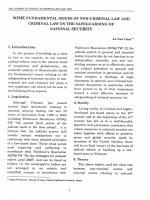
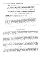
Fig. 1 a X-Ray Diffraction of the
TiO2/CdS/CdSe/ZnS in different
electrolytes, b, c TEM images of
TiO2 film and TiO2/CdS/CdSe/
ZnS, and d UV–Vis absorption
spectra of the TiO2 films sensitized by CdS/CdSe/ZnS QDs
show the light absorption behavior of photoanodes changed with
the SILAR cycles of CdS, CdSe,
and ZnS
studied the influence of the number of SILAR deaths,
annealing temperature on the diffusion process, and the
existence of electrons in QDSSCs through Nyquist,
bode spectra.
2 Experiment
2.1 Investigation on sensitized TiO2 films
The films were coated with TiO2 layers by silk-screen
printing, and they were then annealed at 500 °C for
30 min. Their sizes ranged from 10 to 30 nm
(Transmission Electron Microscopy image in Fig. 1a).
The thickness of TiO2 films was around 4 μm measured
by Stylus spectra. Then, the films were dipped in 40mmol TiCl4 solution for 30 min at 70 °C and sintered
at 500 °C for 30 min. The specific surface area of the
mesoporous TiO2 was examined by using N2 adsorption
and desorption isotherms before and after the calculation. The surface area is 120.6 m2 g−1 (measured by
BET devices). This result indicates that the synthesized
material had a wider mesoporous structure.
c
1000
800
a
600
400
200
20
30
40
50
b
d
2
1
0
400
500
600
700
800
Braz J Phys
TiO2/CdS/CdSe/ZnS films were synthesized by SILAR
method as follows: firstly, the TiO2 film was dipped in
0.5 M Cd2+-ethanol solution for 1 min and rinsed with
ethanol. Then, it was dipped for 1 min in 0.5 M S2−methanol solution and rinsed with methanol after being
dried in the air (a cycle SILAR). The number of CdS
QDs was increased by repeating the assembly cycles
from 1 to 5 cycles. Secondly, TiO2/CdS was dipped into
1 M Cd2+-ethanol solution for 1 min at room temperature
and rinsed with ethanol. Then, it was dipped for 1 min in
0.5 M Se2−-aqueous solution and rinsed with pure water
after being dried in the air (a cycle SILAR). The number
of CdSe QDs was increased by repeating the assembly
cycles from one to five. For the ZnS passivation layer,
TiO2/CdS/CdSe films were dipped into 0.1 M Zn2+-solution and 0.1 M S2−-solutions for 1 min and rinsed with
pure water between two dips (a total of 2 cycles).
Finally, they were annealed in a vacuum environment
with different temperatures to avoid oxidation. TiO 2/
CdS/CdSe/ZnS thickness was measured by the Stylus
spectra. The average thicknesses of CdS (3 cycles),
CdSe (3 cycles), and ZnS (2 cycles) were 351.9, 56.1,
and 257.8 nm, respectively. The coating of F− ions was
performed by dipping the TiO2 photoelectrode into a
1 M NH 4 F aqueous solution for 2 min, rinsed with
deionized water [20]. Two layers of F− ions were coated:
the first was coated before the deposition of CdS QDs,
the second after the deposition of three layers of QDs,
and the same for CdSe.
2.3 Fabrication of QDSSCs
The structure of QDSSCs was designed by the Surlyn
between photoanodes and counterelectrodes at 170 °C.
The electrolyte was filled from a hole made on the counter electrode. The active area of QDSSCs was 0.38 cm2.
The polysulfide electrolyte was 0.5 M Na2S, 0.2 M S, and
0.2 M KCl in Milli-Q ultrapure water/methanol (7:3 by
volume).
SourceMeter via a simulated Air mass 1.5 standard (AM
1.5) sunlight with an output power of 100 mW/cm2 produced by a solar simulator (Solarena, Sweden).
3 Results and Discussions
QDSSCs used these QDs to replace dye in DSSCs. So,
we studied the stability of the photoanodes in different
electrolyte for the examined photovoltaic. Figure 1a
shows the XRD of TiO2/CdS/CdSe/ZnS photoanode in
a
6
Current density (mA/cm2)
2.2 Investigation on TiO2/CdS/CdSe/ZnS films
TiO2/CdSe at 1 hour
TiO2/CdSe at 10 hour
5
TiO2/CdSe at 18 hour
TiO2/CdSe at 20 hour
TiO2/CdSe at 24 hour
4
b
3
2
1
0
0.0
0.1
0.2
0.3
Voltage (V)
c
2.4 Characterizations
The morphology of the investigated samples was observed by means of TEM. The crystal structure was analyzed with an X-ray diffractometer (Philips, PANalytical
X’pert, CuKα radiation). The absorption properties of the
samples were investigated with a diffuse reflectance UV–
Vis spectrometer (JASCO V-670). Photocurrent–voltage
measurements were performed on a Keithley 2400
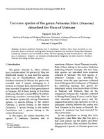
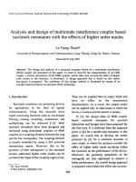
Fig. 2 a–c The J–V curves of the QDSSCs with different photoanodes
under one sun illumination
Braz J Phys
Table 1 Photovoltaic performance parameters of QDSSCs based on
TiO2/CdS and TiO2/CdSe photoanodes
Solar cells
JSC (mA/cm2)
VOC (V)
Fill factor
FF
Efficiency
η (%)
TiO2/CdS at 1 h
TiO2/CdS at 2 h
TiO2/CdS at 3 h
TiO2/CdS at 5 h
TiO2/CdSe at 1 h
TiO2/CdSe at 10 h
TiO2/CdSe at 18 h
TiO2/CdSe at 20 h
TiO2/CdSe at 24 h
0.763
1.87
2.23
1.7
0.256
0.59
2.08
5.47
2.13
0.276
0.38
0.294
0.22
0.31
0.32
0.33
0.33
0.29
0.255
0.242
0.34
0.3
0.25
0.24
0.27
0.31
0.24
0.054
0.17
0.22
0.12
0.02
0.046
0.184
0.575
0.15
different electrolytes. It is clear that the photoanode was
oxidized with I−/I3− electrolyte. Two new peaks appeared
at 34 and 52° positions after the photoanode was immersed in I−/I3− electrolyte. Moreover, there were the
quenched diffraction peaks of the photoanode at 30, 48,
and 54.5°. Meanwhile, the sample immersed in S 2−/Sn2−
electrolytes did not change the structure. Therefore, in
this study, we decided to select the S2−/Sn2− electrolyte
to produce QDSSCs. Detailed morphological features
and crystallinity of the pure TiO2 and TiO2/CdS/CdSe/
ZnS photoanodes were investigated with a TEM image.
Figures 1b, c show a TEM image of pure TiO2 and TiO2/
CdS/CdSe/ZnS photoanodes conducted with the SILAR
cycle numbers of CdS, CdSe, and ZnS at 3, 3, and 2,
respectively. We can see that QDs covered the surface of
TiO2 nanoparticles. It shows that the mean diameter of
QDs is from 2 to 5 nm. The results from TEM demonstrate that the SILAR method is an efficient TiO2 strategy for obtaining the covering QDs on the TiO2 surface.
We know that the optical TiO 2 /CdS/CdSe/ZnS
photoanode was important for conducted photovoltaic.
Table 2 Photovoltaic performance parameters of QDSSCs
based on TiO2/CdS/CdSe/ZnS
photoanodes
Solar cells
TiO2/CdS(1)/CdSe(3)/ZnS(2)
TiO2/CdS(2)/CdSe(3)/ZnS(2)
TiO2/CdS(3)/CdSe(3)/ZnS(2)
TiO2/CdS(4)/CdSe(3)/ZnS(2)
TiO2/CdS(5)/CdSe(3)/ZnS(2)
TiO2/CdS(3)/CdSe(1)/ZnS(2)
TiO2/CdS(3)/CdSe(2)/ZnS(2)
TiO2/CdS(3)/CdSe(4)/ZnS(2)
TiO2/CdS(3)/CdSe(5)/ZnS(2)
TiO2/CdS(3)/CdSe(3)/ZnS(1)
Figure 1d shows the UV–Vis absorption spectra of
photoanodes measured after each cycle of SILAR. As
expected, the absorbance increased with the increasing
cycles of CdS and CdSe. However, only the absorption
spectra with SILAR cycles of TiO 2 /CdS(3)/CdSe(3)/
ZnS(2) photoanode show the best deposition. Under
550-nm wavelength region, an increase in absorption
was due to more CdS loaded on TiO2/CdS/CdSe/ZnS
film. From 550 to 629 nm, a higher deposition degree of
CdSe on TiO2/CdS/CdSe/ZnS electrode resulted in the
shift of the absorption peak toward the red region. The
sizes of QDs were consistent with the sizes measured
from the TEM images. A higher absorption was thus
obtained because the absorption spectrum of ZnS
complemented those of CdSe and CdS QDs.
Furthermore, ZnS acted as a passivation layer to protect
CdS and CdSe QDs from photocorrosion [21].
We conducted a set of QDSSCs based on TiO2/CdS,
TiO2/CdSe, and TiO2/CdS/CdSe/ZnS photoanodes with
polysulfide electrolyte. Figures 2a, b present the J–V
curves of QDSSCs based on TiO2/CdS and TiO2/CdSe
photoanodes with different deposition times (an active area
of 0.38 cm2) at AM 1.5 (100 mW/cm2). The best power
conversion efficiencies of QDSSCs based on TiO2/CdS
and TiO2/CdSe photoanodes were obtained with the deposition times at 3 and 20 h, respectively. Lower power
conversion efficiencies were obtained from the QDSSCs
with deposition times less than 3 h (for CdS) and 20 h (for
CdSe) or more than 3 h (for CdS) and 20 h (for CdSe). The
QDSSCs based on TiO2/CdS (TiO2/CdSe) show an opencircuit voltage (Voc) of 0.294 V (0.33 V), a short-circuit
current density (Jsc) of 2.23 mA/cm2 (5.47 mA/cm2), fill
factor (FF) of 0.34 (0.31), and an energy conversion efficiency (η) of 0.22 % (0.575 %). These are in line with
those reported in [22–24].
The TiO 2 /CdS/CdSe/ZnS co-sensitized solar cells
demonstrated a better performance (1.52 %) than the
JSC (mA/cm2)
2.18
4.28
4.79
5.73
3.05
6.05
4.21
3.30
2.08
7.03
VOC (V)
0.29
0.54
0.76
0.39
0.45
0.356
0.55
0.48
0.33
0.39
Fill factor
Efficiency
FF
η (%)
0.35
0.37
0.41
0.31
0.32
0.256
0.38
0.31
0.27
0.26
0.22
0.86
1.52
0.68
0.45
0.55
0.88
0.50
0.18
0.73
Braz J Phys
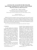
Fig. 3 The energy level alignment of QDSSCs [30]
(1)_TiO2/CdS(1)/CdSe(3)/ZnS(2)
(2)_TiO2/CdS(2)/CdSe(3)/ZnS(2)
1200
(3)_TiO2/CdS(3)/CdSe(3)/ZnS(2)
(4)_TiO2/CdS(4)/CdSe(3)/ZnS(2)
Z'' (Ohm)
(5)_TiO2/CdS(5)/CdSe(3)/ZnS(2)
(5)
900
(4)
a
(1)
600
300
(2)
(3)
0
0
500
1000
1500
2000
Z' (Ohm)
b
TiO2/CdS(3)/CdSe(1)/ZnS(2)
TiO2/CdS(3)/CdSe(2)/ZnS(2)
2000
TiO2/CdS(3)/CdSe(3)/ZnS(2)
(5)
TiO2/CdS(3)/CdSe(4)/ZnS(2)
TiO2/CdS(3)/CdSe(5)/ZnS(2)
Z'' (Ohm)
TiO2/CdS (0.22 %) and TiO2/CdSe QDSSC (0.575 %)
(shown in Tables 1 and 2) [25]. This suggests that the
charge injection from CdSe conduction level to TiO2
conduction level may not be effective, due to the quasiFermi levels of CdSe being lower than that of TiO2 [26].
However, the quasi-Fermi level of CdS quantum dots
was higher than that of the TiO2 layer [27], and it is
expected to improve the charge injection from CdSe to
TiO2. Moreover, a ZnS coating formed a potential barrier
between QDs and the electrolyte, which blocked the
electrons in the CB from QDs to the electrolyte and
reduced the defect states in QDs [28]. So, the electron
density in the conduction band of QDs increased and the
enhanced JSC was obtained. And thus, a high performance was obtained. In addition, with the increasing
electron density in the conduction band of QDs, the
quasi-Fermi level correspondingly increased and consequently, VOC = (EFn–EFo)/(−q) increased (Fig. 3). With
the combination of CdS, CdSe, and ZnS, the CdS
Fermi energy level was higher than that of TiO2, and
beneficial effects were conferred to the coupled QDSSCs
system. It is evident that the parameters of the coupled
QDSSCs were influenced by CdS/CdSe/ZnS cosensitization cycles [29]. This is because CdS, CdSe,
and ZnS QDs led to the quasi-Fermi level alignment
and it resulted in a cascade energy level structure in the
order of CB TiO2
elevated the conduction band edge of CdSe, making a
higher driving force for the injection of stimulated electrons out of the CdSe layer [25]. Moreover, the photocurrent density might be enhanced with QDs loaded by
means of increasing coating cycles [28].
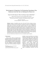
To further investigate the dynamic resistance of
QDSSCs, the electrochemical impedance spectra (EIS)
under illuminated conditions for QDSSCs with different
CdS and CdSe SILAR cycles were carried out to research the charge transfer process [29]. Figures 4a–c
show the Nyquist plots of TiO 2 /CdS and TiO 2 /CdSe
(4)
1000
c
(1)
(2)
0
(3)
1000
2000
Z' (Ohm)
3000
4000
d
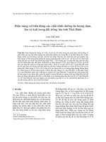
Fig. 4 a, b Nyquist and Bode impedance plots of EIS spectra measured
under the illuminated conditions for QDSSCs with CdS SILAR cycles
from one to five layers and c, d CdSe SILAR cycles from one to five
layers
Braz J Phys
Table 3 The resistance and lifetime obtained from the EIS measurements of TiO2/CdS/CdSe/
ZnS for different CdS SILAR
cycles
No
Sample
RS (Ω)
Rct2 (Ω)
Rct1 (Ω)
τ (ms)
1
2
3
4
5
TiO2/CdS(1 layer)/CdSe(3)/ZnS(2)
TiO2/CdS(2 layers)/CdSe(3)/ZnS(2)
TiO2/CdS(3 layers)/CdSe(3)/ZnS(2)
TiO2/CdS(4 layers)/CdSe(3)/ZnS(2)
TiO2/CdS(5 layers)/CdSe(3)/ZnS(2)
21.9
33.9
38.1
35.4
26
351
333
83.5
1930
16,100
1,570
158
9.21
2330
59,100
4.9
3.2
3.2
1.6
1.8
QDSSCs when SILAR cycles of CdS changed from one
to five. The EIS illustrated two semicircles at high frequency and low frequency. The small semicircle was due
to the resistance against movement of charge at Pt/
electrolyte (Rct1) and FTO/TiO2 interface. Meanwhile,
the large semicircle was due to a resistance against the
electron diffusion in the TiO2 and the charge recombination resistance at the TiO2/QDs/electrolyte interface
(Rct2) and against the inner diffusion in an electrolyte
(Zw). With Fit & Simulator software, we fitted for EIS of
all samples and the values of Rs, Rct1, and Rct2 are listed
in Tables 3 and 4. Rs is a set of resistance to the charge
transfer at Ag/FTO/TiO2 front contact and Ag/FTO/Pt
back contact; Rs values are obtained at about 38.1 Ω
for the best photoanodes. The result shows that the
applied technique is significant.
We can find in Fig. 4a–c that the radius of the semicircles increased when SILAR cycles of CdS or CdSe were
under three layers or over three layers. Compared with the
other photoanodes, the TiO 2 /CdS(3)/CdSe(3)/ZnS(2)
photoanode exhibited a smaller Rct1 and Rct2 (9.21 and
83.5 Ω) and larger lifetime (3.2 ms) (shown in Tables 3
and 4). Also, it shows a fast electron transfer at TiO2/QDs/
electrolyte interface and reduction in recombination as a
ZnS coating protected CdS/CdSe QDs [31]. With increasing SILAR cycles of CdS and CdSe over three layers, the
dynamic resistance increased. This is because the amount
of CdS and CdSe loaded more on TiO2/CdS/CdSe/ZnS,
which indicated the increasing recombination in
photoanodes. The results show that the photogenerated
electrons were captured by the defect states in QDs. So
Table 4 The resistance and lifetime obtained from the EIS measurements of TiO2/CdS/CdSe/
ZnS for different CdSe SILAR
cycles
the electron transfer was more diffusive hindrance, which
increased charge recombination and back transport
reaction.
Figures 4b–d indicate the Bode plots of the TiO2/
CdS and TiO2/CdSe QDSSCs when SILAR cycles of
CdS changed from one to five. We find that the frequency peak of the charge transport process isshifted to
the lowest frequency region corresponding to TiO 2 /
CdS(3)/CdSe(3)/ZnS(2) photoanode. Therefore, it indicates that the lifetime of the electron in the TiO 2 /
CdS(3)/CdSe(3)/ZnS(2) film increases, which favors
the electron transfer with less diffusive hindrance.
Hodes and co-workers found that the lifetime of electron transfer into TiO2 reached 10−12 s (very fast) and
that of electron recombination got 10 −6 s [32]. It is
shorter than the lifetime of electrons in the conduction
band of QDs (calculated in this paper about 3.2 ms). So
the charge transfer in the conduction band increased.
4 Conclusions
We successfully fabricated the QDSSCs based on the TiO2/
CdS, TiO2/CdSe, and TiO2/CdS/CdSe/ZnS photoanode. The
TiO2/CdS/CdSe/ZnS co-sensitized solar cells demonstrated a
better performance (1.52 %) than those of the TiO2/CdS
(0.22 %) and TiO2/CdSe QDSSC (0.575 %). This is because
a ZnS coating formed a potential barrier between QDs and the
electrolyte, which blocked the electrons in the conduction
band from QDs to the electrolyte and reduced the defect states
in QDs. The dimension of the semicircles increased when
No
Sample
RS (Ω)
Rct2 (Ω)
Rct1 (Ω)
τ (ms)
1
2
3
4
5
TiO2/CdS(3)/CdSe(1 layer)/ZnS(2)
TiO2/CdS(3)/CdSe(2 layers)/ZnS(2)
TiO2/CdS(3)/CdSe(3 layers)/ZnS(2)
TiO2/CdS(3)/CdSe(4 layers)/ZnS(2)
TiO2/CdS(3)/CdSe(5 layers)/ZnS(2)
28.6
67
38.1
24.8
21.3
1,670
1,190
83.5
385
415
106
268
9.21
179
243
5.9
4.9
3.2
1.7
1.8
Braz J Phys
SILAR cycles of CdS and CdSe were under three layers or
over three layers. Compared with the other photoanodes, the
TiO2/CdS(3)/CdSe(3)/ZnS(2) photoanode exhibited a smaller
Rct1 and Rct2 (9.21 and 83.5 Ω) and larger lifetime (3.2 ms).
The results show a fast electron transfer at TiO2/QDs/electrolyte interface and a reduction in recombination when a ZnS
coating protected CdS/CdSe QDs [26].
Acknowledgments This work was supported by Vietnam National
University by the name of the project: B 2012-18-5TD, the University
of Science of Ho Chi Minh City and Dong Thap University.
References
1. A.J. Nozik, Quantum Dot Solar Cells Physica E 14, 115–120 (2002)
2. M.A. Green, K. Emery, Y. Hishikawa, W. Warta, Prog Photovolt 17,
320–326 (2009)
3. I. Robel, M. Kuno, P.V. Kamat, Size-dependent electron injection
from excited CdSe quantum dots into TiO2 nanoparticles. J. Am.
Chem. Soc. 129(14), 4136–4137 (2007)
4. A.Z. Peng, P. Peng, Formation of high-quality CdTe, CdSe, and CdS
nanocrystals using CdO as precursor. J. Am. Chem. Soc. 123(1),
183–184 (2001)
5. R. Vogel, K. Pohl, H. Weller, Sensitization of highly porous, polycrystalline TiO2 electrodes by quantum sized CdS. Chem. Phys. Lett.
174(3), 241–246 (1990)
6. H.-J. Lee, D.-Y. Kim, J.-S. Yoo, J. Bang, S. Kim, S.-M. Park,
Anchoring cadmium chalcogenide quantum dots (QD) onto stable
oxide semiconductor for QD sensitized solar cells. Bull. Kor. Chem.
Soc. 28, 953–958 (2007)
7. H.-J. Lee, J.-H. Yum, H.C. Leventis, S.M. Zakeeruddin, S.A. Haque,
P. Chen, S.I. Seok, M. Gratzel, M.-K. Nazeeruddin, CdSe quantum
dot-sensitized solar cells exceeding efficiency 1 % at full sun intensity. J. Phys. Chem. C 112, 11600–11608 (2008)
8. W.J. Lee, S.H. Kang, S.-K. Min, Y.-E. Sung, S.-H. Han, Cosensitization of vertically aligned TiO2 nanotubes with two different
sizes of CdSe quantum dots for broad spectrum. Electrochem.
Commun. 10, 1579–1582 (2008)
9. J.Y. Kim, K. Lee, N.E. Coates, D. Moses, T.Q. Nguyen, M. Dante,
A.J. Heeger, Efficient tandem polymer solar cells fabricated by allsolution processing. Science 317(5835), 222–225 (2007)
10. T. Lopez-Luke, A. Wolcott, L.-P. Xu, S. Chen, Z. Wen, J. Li, E.D.L.
Rosa, J.Z. Zhang, Nitrogen-doped and CdSe quantum-dot-sensitized
nanocrystalline TiO2 films for solar energy conversion applications.
J. Phys. Chem. C 112, 1282–1292 (2008)
11. I. Mora-Sero, S. Gimenez, T. Moehl, F. Fabregat-Santiago, T. LanaVillareal, R. Gómez, J. Bisquert, Factors determining the photovoltaic performance of a CdSe quantum dot sensitized solar cell: the role
of the linker molecule and of the counter electrode. Nanotechnology
19, 424007 (2008)
12. Q. Shen, J. Kobayashi, L.J. Diguna, T. Toyoda, Effect of ZnS coating
on the photovoltaic properties of CdSe quantum dot-sensitized solar
cells. J. Appl. Phys. 103, 084304 (2008)
13. Y. Tachibana, K. Umekita, Y. Otsuka, S. Kuwabata, Performance
improvement of CdS quantum dots sensitized TiO2 solar cells by
introducing a dense TiO2 blocking layer. J. Phys. D. Appl. Phys. 41,
102002 (2008)
14. S. Cheng, W. Fu, H. Yang, L. Zhang, J. Ma, H. Zhao, M. Sun, L.
Yang, Photoelectrochemical performance of multiple semiconductors
15.
16.
17.
18.
19.
20.
21.
22.
23.
24.
25.
26.
27.
28.
29.
30.
31.
32.
(CdS/CdSe/ZnS) cosensitized TiO2 photoelectrodes. J. Phys. Chem.
C 116, 2615–2621 (2012)
V. Senthamilselvi, V. Senthamilselvi, K. Saravanakumar, N.J.
Begum, R. Anandhi, A.T. Ravichandran, B. Sakthivel, K.
Ravichandran, Photovoltaic properties of nanocrystalline CdS films
deposited by SILAR and CBD techniques—a comparative study. J.
Mater. Sci. Mater. Electron. 23, 302–308 (2012)
H.J. Lee, M. Wang, P. Chen, D.R. Gamelin, S. M. Zakeeruddin, M.
Gratze, M. K. Nazeeruddin MK. Efficient CdSe quantum dotsensitized solar cells pre-pared by an improved successive ionic layer
adsorption and reaction process. Nano Letters B 4221–7 (2009)
C.Y. Kuo, W.C. Tang, C. Gau, T.F. Guo, D.Z. Jeng, Ordered bulk
heterojunction solar cells with vertically aligned TiO2 nanorods embedded in a conjugated polymer. Appl. Phys. Lett. 93, 033303–
033307 (2008)
J. Jasieniak, M. Califano, S.E. Watkins, Size-dependent valence and
conduction band-edge energies of semiconductor nanocrystals. ACS
Nano 5, 5888–5902 (2011)
Y. Zhou, M. Eck, M. Kruger, Bulk-heterojunction hybrid solar cells
based on colloidal nanocrystals and conjugated polymers. Energy
Environ Sci 3, 1851–1864 (2010)
A. Tubtimtae, M.W. Lee, Effects of passivation treatment on performance of CdS/CdSe quantum-dot co-sensitized solar cells. Thin
Solid Films 526, 225–230 (2012)
Z. Tachan, M. Shalom, I. Hod, S. Ruhle, S. Tirosh, A. Zaban, PbS as
a highly catalytic counter electrode for polysulfide-based quantum
dot solar cells. J. Phys. Chem. C 115, 6162–6166 (2011)
G. Hodes, A. Albu-Yaron, F. Decker, P. Motisuke, Three-dimensional
quantum-size effect in chemically deposited cadmium selenide films.
Phys. Rev. B 36, 4215–4221 (1987)
N. Kopidakis, N.R. Neale, A.J. Frank, Effect of an adsorbent on
recombination and band-edge movement in dye-sensitized TiO2
solar cells: evidence for surface passivation. J. Phys, Chem B 110,
12485–12489 (2006)
V.G. Pol, A. Zaban, Growing TiO2-based pillars by chemisorbed
nanotitania followed by annealing. J. Phys, Chem C 111, 14574–
14578 (2007)
C.H. Chang, Y.L. Lee, Chemical bath deposition of CdS quantum
dots onto mesoscopic TiO2 films for application in quantum-dotsensitized solar cells. Appl. Phys. Lett. 91, 053503 (2007)
N. Balisa, V. Dracopoulosb, K. Bourikasc, P. Lianos, Quantum dot
sensitized solar cells based on an optimized combination of ZnS, CdS
and CdSe with CoS and CuS counter electrodes. Electrochim Acta
91, 246–252 (2013)
J.Y. Kim, S.B. Choi, J.H. Noh, S.H. Yoon, S.W. Lee, T.H. Noh, A.J.
Frank, K.S. Hong, Synthesis of CdSe−TiO2 Nanocomposites and
Their Applications to TiO2 Sensitized Solar Cells. Langmuir 25,
5348 (2009)
G.V. Chris, J. Neugebauer, Universal alignment of hydrogen levels in
semiconductors, insulators and solutions. Nature 423, 626–628
(2003)
F. Santiago, J. Bisquert, G. Belmonte, G. Boschloo, A. Hagfeldt,
Influence of electrolyte in transport and recombination in dyesensitized solar cells studied by impedance spectroscopy. Sol.
Energy Mater. Sol. Cells 87, 117–131 (2005)
S. Ruhle, M. Shalom, A. Zaban, Quantum-dot-sensitized solar cells.
ChemPhysChem 11, 2290–2304 (2010)
A. Tubtimtae, M.W. Lee, Effects of passivation treatment on performance of CdS/CdSe quantum-dot co-sensitized solar cells. Thin
Solid Films 526, 225–230 (2012)
G. Hodes, Comparison of dye- and semiconductor-sensitized porous
nanocrystalline liquid junction solar cells. J. Phys. Chem. C 112,
17778–17787 (2008)