DSpace at VNU: Investigation of polymeric composite films using modified TiO2 nanoparticles for organic light emitting diodes
Bạn đang xem bản rút gọn của tài liệu. Xem và tải ngay bản đầy đủ của tài liệu tại đây (447.18 KB, 7 trang )
Send Orders of Reprints at
14
Current Nanoscience, 2013, 9, 14-20
Investigation of Polymeric Composite Films Using Modified TiO2 Nanoparticles for
Organic Light Emitting Diodes
Do Ngoc Chung1, Nguyen Nang Dinh1*, David Hui2, Nguyen Dinh Duc1, Tran Quang Trung3 and
Mircea Chipara4
1
University of Engineering and Technology, Vietnam National University, Hanoi, 144 Xuan Thuy Road, Cau-Giay District, Hanoi,
Vietnam; 2The University of New Orleans, Department of Mechanical Engineering, New Orleans, LA, USA; 3University of Natural
Science, Vietnam National University, Ho Chi Minh City, 227 Nguyen Van Cu Road, District 5, Ho Chi Minh City, Vietnam; 4Mircea
Chipara, The University of Texas Pan-American, Department of Physics and Geology, Edinburg, 78541, TX, USA
Abstract: Nanocomposite films for hole transport and emitting layer were prepared from poly(3,4-ethylenedioxythiophene),
poly(styrenesulfonate), and poly[2-methoxy-5-(2'-ethylhexyloxy)-1,4-phenylene vinylene] - as MEH-PPV - incorporated with anatase
(TiO2) nanoparticles dispersed in oleic acid. The precursor for the sol was a solution of tetraiso-propyl orthotitanate [Ti(iso-OC3H 7)4 ].
The research showed that both the electrical and spectral properties of the conjugated polymers were enhanced due to the incorporation of
anatase. The best volume ratio between the oleic acid precursor and tetraiso-propyl orthotitanate was found to be of 10. Current-voltage
characteristics of organic light emitting diodes made from these nanocomposite films were considerably enhanced in comparison with
those made from pure polymers. The luminous efficiency is reported. Mechanical properties of the nanocomposite materials, (in particular for MEH-PPV-TiO 2) were found to be dependent on constituent organic and inorganic materials and on the geometric position of constituents. It was concluded that such composite organic light emitting diodes can exhibit larger performance efficiency and longer lifetimes than classical light emitting diodes.
Keywords: Conducting polymers, current-voltage characteristics, energy gap, luminous efficiency, nanocomposite, organic light emitting
diodes, photoluminescence, TiO2 nanoparticles.
1. INTRODUCTION
Organic light emitting diodes (OLEDs) have been intensively
investigated during the last decade, because of their potential applications (such as optoelectronics, urban lighting, screen for TV and
cellular phones, large-area displays, solar flexible cells, etc [1-4]).
However, in order to replace the light emitting diodes (LEDs) based
on inorganic semiconducting materials it is necessary to improve
both the efficiency and time of service of the OLEDs. While
OLEDs and in particular polymer-based OLEDs did not yet reach
the efficiency of inorganic LEDs, the difference between LEDs and
OLEDs efficiencies is decreasing continuously. Polymeric LEDs
are expected to present several advantages such as low cost (derived from the anticipation of future technologies, which will allow
the printing of polymeric LEDs), outstanding mechanical properties
(including flexibility), reduced weight, low operational voltage (by
replacing ITO with conducting polymers), and good quantum efficiency. The lifetime of OLEDS is typically restricted by environmental issues (most important being represented by oxygen, water
or moisture, and polymer aging) and intrinsic contributions controlled by atom diffusion and interfacial processes. Research efforts
are aiming in particular at increasing the efficiency and the lifetime
of polymer-based LEDs.
The mechanical properties of composite materials (and in particular of nanocomposites) are strongly dependent on the constituent materials nature, size, and concentration as well as on the interface between the polymeric matrix and the nanofiller, on the manufacturing technology, and on geometric position of constituents in
the composite/final product. Up to now, many researchers have
investigated mechanical properties of polymer composite reinforced
by nanoparticles [5-8]. They tried to explain the mechanical
*Address correspondence to this author at the University of Engineering and
Technology, Vietnam National University, Hanoi, 144 Xuan Thuy Road,
Cau-Giay District, Hanoi, Vietnam; Tel:/Fax: + 84 4 3754 9429;
E-mail:
1875-6786/13 $58.00+.00
properties of polymer-based nanocomposites by neglecting the
interactions between nanoparticles. A brief analysis of the mechanical properties of OLEDs, which takes into account the interactions
between nanoparticles, is presented.
The efficiency of the optoelectronic devices like OLED, is controlled by three factors: (i) equalization of injection rates of positive
(hole) and negative (electron) charge carriers (ii) recombination of
the charge carriers to form singlet exciton in the emitting layer
(EML) and (iii) radiative decay of excitons. Recently, novel approaches to deal with these problems have been reported [9, 10]
such as the addition of a hole transport layer (HTL) between the
transparent anode and the emitting layer (EML) [9] and/or of an
electron transport layer (ETL) sandwiched between the EML and
cathode [10]. With these solutions one can enhance the electroluminescent efficiency of OLEDs. However, the long-lasting service
is sometimes limited. The other way to enhance both the efficiency
and the service duration of the device is to use nanocomposite films
instead of pure polymers (served as HTL and EML). Embedded
nanoparticles of oxides can substantially influence the mechanical,
electrical and optical properties of the polymer. For instance, thin
films of nanocrystalline anatase (nc-TiO2) particles dispersed within
poly[2-methoxy-5-(2'-ethylhexyloxy)-1,4-phenylene
vinylene]
(MEH-PPV) were studied as photoactive material [11]. By adding a
hole transport layer (HTL) and an electron transport layer (ETL) to
the three-layer device, the equalization of injection rates of hole and
electron was improved and a higher electroluminescent efficiency
of the OLED was obtained [12]. However, a large difference between the structure of the inorganic material (ITO) and the organic
polyethylene (3,4-dioxythiophene) (PEDOT) usually causes a poor
interface contact between them. Recently, the role of nanocomposites obtained by embedding TiO2 nanoparticles in PEDOT or
MEH-PPV on the I-V characteristics of OLEDs made from these
composites, was reported [12]. Since the TiO2 nanoparticles used to
make the composites were taken from commercial sources, it was
difficult to modify their surfaces in order to reach atomically con© 2013 Bentham Science Publishers
Investigation of Polymeric Composite Films Using Modified TiO2
Current Nanoscience, 2013, Vol. 9, No. 1
tinuous TiO2/polymer interfaces (or heterojunctions). This strongly
blocked the charge transport through these interfaces.
In this work, the results of the research on the preparation and
modification of TiO2 nanoparticles used for the fabrication of
OLEDs, are reported. Structural, electrical and spectroscopic properties of the dispersive particles and the nanocomposite films of
PEDOT+nc-TiO2 and MEH-PPV+nc-TiO2 as well as currentvoltage (I-V) characteristics of the devices made from the films
were investigated. The mechanical properties of MEH-PPV+ncTiO2 vs. TiO2 volume are also analyzed.
2. EXPERIMENTAL
Sol-gel method was used to prepare nanoparticles of TiO2 with
modified surface. The catalyst was trimethylamino-N-oxide dihydrate [(CH3)3NO.2H2O] with oleic acid as the derivative chemical
agent. The precursor for the sol is a solution of tetraiso-propyl orthotitanate [Ti(iso-OC3H7)4]. The precursor was mixed with oleic
acid (C17H33COOH) in water and (CH3)3NO.2H2O. This mixture
was stirred at 80oC for up to 2 hours (when the homogeneous clear
orange was obtained). To find out the optimum volume of oleic
acid, various volume ratios of oleic acid per the precursor (r), ranging from 1.5 to 10 (see Table 1), were chosen. The spectroscopic
properties of the TiO2 solutions were measured in quartz cells. TiO2
powder was obtained by pouring the solution onto silicon substrates
followed by annealing at 180oC, in air, for 3 hours. Annealing at
such a low temperature makes difficult the growing process of TiO2
particles, consequently the size of particles can be maintained at the
same size of the dispersed TiO2.
To deposit nanocomposite films, MEH-PPV was dissolved in
xylene (8 mg of MEH-PPV in 10 ml of xylene). TiO2 was then
embedded in PEDOT-PSS (PEDOT+nc-TiO2) with 15 wt % of
TiO2 and in MEH-PPV with 20 wt % of TiO2 (MEH-PPV+ncTiO2). These concentrations were taken from the optimal values of
the TiO2 embedded within these polymers, which were obtained
and reported elsewhere [13], where commercial TiO2 nanoparticles
with 5 nm in size were utilized. Using dispersed nc-TiO2 particles
one can expect to enhance the energy and charge transport through
the TiO2/polymer interfaces. Both the ultrasonic and magnetic stirring at temperature of 45 oC was used to achieve a homogenous
distribution of TiO2 within these polymers The PEDOT+nc-TiO 2
and MEH-PPV+nc-TiO2 were deposited onto ITO/glass substrates
by spin coating, then heated at 120 oC in a vacuum of 1.33 Pa for 1
hour to evaporate completely the solvent. The thickness of polymer
layers was controlled both by the spinning rate and the viscosity of
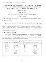
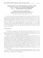
the solution. Details of the heterojunctions of these devices are shown in
Fig. (1). Each ITO/glass substrate slide consists of four devices, which
have dimensions of 2 mm 2 mm or 4 mm2 in area.
The heterojunctions of the as obtained OLEDs are shown in
Fig. (1). The following abbreviations will be used:
Table 1.
15
(-)
Al
MEH-PPV + (nc -TiO2)
PEDOT + (nc -TiO2)
ITO
glass
(+)
Fig. (1). Design of an OLED based on polymeric nanocomposites.
H1: PEDOT/MEH-PPV
H2: PEDOT/MEH-PPV+nc-TiO2
H3: PEDOT+nc-TiO2 /MEH-PPV
H4: PEDOT+nc-TiO2/ MEH-PPV+nc-TiO2
and for the devices made from corresponding heterojunctions:
NP0: ITO/PEDOT+nc-TiO2/Al
N1: ITO/PEDOT/MEH-PPV/Al
N2: ITO/PEDOT/MEH-PPV+nc-TiO2/Al
N3: ITO/PEDOT+nc-TiO2 /MEH-PPV/Al
N4: ITO/PEDOT+nc-TiO2/ MEH-PPV+nc-TiO2/Al
The surface morphology of samples was characterized by using
a “Hitachi” Field Emission Scanning Electron Microscopy (FESEM). Atomic force microscope (AFM) images were obtained
using a NT-MDT Atomic Force Microscope operating in a tunnel
current mode. Nanocrystalline structures were investigated by XRay Diffraction (XRD) with a Bruker D-Advance-8 diffractometer
using filtered Cu K radiation ( = 0.15406 nm). Photoluminescence spectra (PL) were carried-out by using a FL3-2 spectrophotometer and Current-voltage (I-V) characteristics were measured on
an Auto-Lab Potentiostat PGS-30. The ultraviolet-visible absorption spectra were carried out on a Jasco UV-VIS-NIR V570.
3. RESULTS AND DISCUSSION
3.1. Properties of Dispersive TiO2
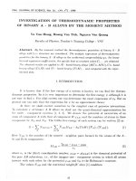
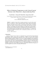
Fig. (2) shows the absorption spectra of TiO2 solutions vs. the
volume ratio of oleic acid per precursors. From this figure one can
see that solely MEH-PPV exhibits a peak in UV-VIS, in agreement
with experimental data reported elsewhere [13]. The absorption
edge of the samples is blue shifted with the increase of the r ratio
(see the left panel of Fig. 1). The absorption edges corresponding to
r equal from 1.5 to 10 are located from 354 nm to 308 nm.
Volumes of Compound Taking Part in the Synthesis of Dispersed TiO2 Particles in Oleic Acid with Different Ratio (r)
r
Acid oleic (ml)
Precursor (ml)
H2O (ml)
Catalyst (ml)
1.5
3.6
2.40
4.25
1.85
2.0
3.6
1.80
3.75
1.60
3.0
3.6
1.20
3.00
1.25
5.0
3.6
0.72
2.50
1.00
7.0
3.6
0.52
2.25
0.85
10.0
3.6
0.36
2.00
0.65
16 Current Nanoscience, 2013, Vol. 9, No. 1
Chung et al.
2.0
r =1.5
1.5
3
Absorption [Arb. Units]
Absorption (Ab.units)
2.5
2
5
7
1.0
10
MEH-PPV
0.5
0.0
300
400
500
600
1.5
1.0
0.5
r=2
0.0
14
700
5x10
Wavelength (nm)
14
14
7x10
6x10
Frequency (Hz)
14
8x10
Fig. (2). Left panel: Absorption spectra of TiO2-dispersed solutions with different concentration of oleic acid. Right Panel: Experimental data (gray line) and
best fit (red line) for the sample with r=2 by using eq. 2.
Table 2.
The Band Gap Value of Dispersed TiO2 vs. r-ratio Estimated from the UV-Vis Spectra
Ratio (r)
1.5
2.0
3.0
5.0
7.0
10.0
EG (eV)
2.15±0.05
2.17±0.05
2.16±0.05
2.24±0.05
2.33±0.06
2.37±0.07
UV-Vis data at short wavelength can be used to estimate the
energy gap, EG, of the dispersed nano-TiO2 particles (Table 2). by
using the expression [14]:
=
A
(h
h
EG )n
(1)
Where h is Planck's constant, is the frequency of the incident
UV-Vis radiation, A is a constant and n is 0.5 for direct band semiconductors and 2 for indirect band gap semiconductors. As expected, best fits were obtained for n=2 (indirect band).
The gap energies calculated from UV-VIS data were significantly smaller than the gap energy of pristine (bulk) TiO2, which is
in the range 3 to 3.3 eV [15]. This result is a contribution of several
competing processes:
1. In confined semiconductors, the energy gap is size dependent
[1], [13]:
EG( R) = EG
2 2
1.8e2
1
1
+
+
R
8R 2 me mh
(2)
where EG( ) is the energy gap of the bulk semiconductor, EG(R) is the
energy gap of a semiconductor of radius R, me is the effective mass
of the electron, mh is the effective mass of the hole, e represents the
electronic charge, and the dielectric permittivity of the nanoparticle. The dependence of the energy gap on the particle size is rather
complex due to the competition between the dipolar interaction
term (second term in eq. 2), which tends to decrease the energy gap,
and the confinement (last) term (which tends to increase the energy
gap) [15]. In the case of TiO2 nanoparticles such competition results
in the increase of the energy gap as the size of nanoparticles is increased (for nanoparticles characterized by a diameter of 5 nm or
larger) [15].
2. Nanocrystals have a high fraction of structural defects-due to
their large surface to volume ratio. These defects can decrease the
energy gap through the formation of defects' bands within the forbidden gap.
3. Actually, the gap energy was estimated for a composite that
involve both conducting polymers and semiconducting nanoparticles. It is expected that the conducting polymer will decrease the
energy gap of the semiconducting nanoparticles, typically via the
opening of an impurity band within the energy gap of the semiconductor.
In order to identify the process responsible for the observed
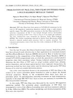
changes of the energy gap, complementary XRD investigations
were performed. The XRD pattern of the TiO2/Si sample made
from the solution with the smallest r (i.e. r =1.5) shown in Fig. (3).
There are six diffraction peaks which are quite consistent with the
peaks for anatase phase of TiO2 crystals [16]. Two intense peaks of
the (021) and (211) directions correspond to the interplanar distances d = 0.240 nm and 0.192 nm, three weaker peaks of (111),
(130) and (113) to 0.285 nm, 0.170 nm and 0.149 nm, respectively,
and the weakest peak of (121) – to 0.212 nm. The fact that the peak
width is rather large shows that the TiO2 anatase powder consists of
rather small particles. Scherrer formula was used to obtain the average particle size R:
0.9
(3)
R=
cos
where is wavelength of the X-ray used ( = 0.15406 nm), the
peak width of half height in radians and the Bragg angle of the
considered diffraction peak [17]. From the XRD patterns the average size of the particles was determined to range from 8 to 9 nm.
The size of TiO2/Si sample with the largest r was found to be of 7
nm (using the same procedure). Thus XRD results also confirmed
the reduction of the particles size with the increase of the r-ratio (as
the estimated size of TiO2 nanoparticles is larger than 5 nm).
For the sample with r < 10, the absorption spectra edge of dispersed TiO2 overlapped a part of the absorption spectra of MEHPPV, for the sample with r 10, the absorption edge of TiO2 did
not affect to the absorption spectra of MEH-PPV (Fig. (2)). The
volume ratio (r = 10) of oleic acid per the precursor [Ti(isoOC3H7)4] was used to synthesize and modify TiO2 nanoparticles.
The slight increase of the energy gap, reported in Table 2 is supported by the weak enhancement of the size of TiO2 nanoparticles,
as expected for TiO2 clusters larger than 5 nm [15].
Investigation of Polymeric Composite Films Using Modified TiO2
Current Nanoscience, 2013, Vol. 9, No. 1
17
Intensity (CPS)
400
300
200
(021)
(211)
(130)
(111)
(113)
(121)
100
0
30
40
50
60
70
2q (degree)
3.2. Nanocomposites Films
PEDOT has been used for the HTL in OLED because it has a
high transmission in the visible region, a good thermal stability, and
a high conductivity [18, 19]. To enhance the interface contact between ITO and PEDOT, dispersive TiO2 nanoparticles were embedded within PEDOT. Fig. (4) shows the AFM of a PEDOT composite with a percentage of 15 wt % of dispersed TiO2 nanoparticles
(7 nm in size). With such a high resolution of the AFM one can see
a distribution of nanoparticles in the polymer due to the spincoating process. For the pure PEDOT, the surface exhibits smoothness comparable to the one of the area surrounding the nanoparticles. TiO2 nanoparticles contributed to the roughness of the composite surface and created numerous TiO2/ PEDOT boundaries in
the composite film.
Fig. (5). FE-SEM micrograph of a MEH-PPV+nc-TiO2 nanocomposite film
(with 20 wt % nc- TiO2 particles) used for the EL in OLED.
4.0
Current Density (mA/cm2)
Fig. (3). XRD patterns of TiO2 powders removed from silicon substrates for
a TiO2/Si sample with r = 1.5.
c
b
a
3.0
2.0
1.0
0
0.2
0.4
0.6
0.8
1.0
1.2
1.4
Voltage (V)
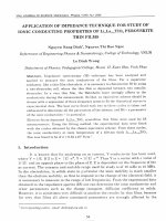
Fig. (6). I-V characteristics of the ITO/PEDOT+nc-TiO2 /Al device for a
spin rate of 1500 rpm (a), 1700 rpm (b) and 2000 rpm (c).
Fig. (4). AFM micrograph of a PEDOT+nc-TiO2 nanocomposite film with
15 wt % of nc-TiO2.
Surfaces of MEHPPV+TiO2 nanocomposite films were examined by FE-SEM. Fig. (5) shows images of a nanocomposite sample
with embedding of 20 wt % dispersed TiO2 particles (7 nm in size).
The surface of this film appears much smoother than the one of
composites with a larger percentage of TiO2 particles or with larger
size TiO2 particles. The influence of the heat treatment on the morphology of the films was weak, i.e. no noticeable differences in the
surface were observed in samples annealed at 120oC, 150oC or
180oC in vacuum. The best annealing temperature for other proper-
ties such as the I-V characteristics and PL spectra was found to be
150 oC. In the sample considered, the distribution of TiO2 nanoparticles is mostly uniform, except for a few bright points indicating
the presence of nanoparticle clusters.
Different spinning rate for coating were considered in order to
find out optimal thickness of the thin composite films, The I-V
characteristics vs. spinning rate of the heterojunction based on PEDOT+nc-TiO2 (15 wt % of TiO2) are shown in Fig. (7). From this
figure one can see that the larger spin rate are associated with the
smaller turn-on voltage of the device. At spinning rates larger or
equal to 2000 rpm, the spun films were too thin and the I-V curve
became worse. Thus, further spin rates of 2000 rpm were used
to deposit PEDOT composite films. Similar results were observed for MEH-PPV+nc-TiO 2 (20 wt % of TiO2) composite
films, but a slight difference was obtained for the spin rate,
i.e. the best spin rate was found to be of 2400 rpm. This can be
explained by the different final thicknesses and TiO2 concentrations of these polymers, as well as by the viscosities/solubilities of the conducting polymers.
In Fig. (7) the absorption spectra in the wavelength from 300 to
600 nm are presented. The inset shows the absorption spectra of the
sample (in a shorter wavelength range, from 300 to 400 nm). It is
seen that TiO2 nanoparticles embedded in the films do not affect
significantly the absorption spectra (as noticed in Fig. (1) for r =
10), except for a slight decrease of the absorption peak in composite
Chung et al.
1.2
1.0
Absorption
Absorption (Ab.units)
1.4
0.6
H1:
H2:
H3:
H4:
H1
PEDOT /MEH-PPV
PEDOT /MEH-PPV+nc-TiO 2
PEDOT +nc-TiO 2/MEH-PPV
PEDOT +nc-TiO 2/MEH-PPV+nc-TiO 2
0.8
0.4
H3
H4
H2
0
300
0.2
350
400
Wavelength (nm)
300
400
500
600
Wavelength (nm)
Fig. (7). Absorption spectra of OLEDs with use of different nanocomposites.
PL - Intensity (ab. units)
250
H1: PEDOT/MEH-PPV
H1 H2: PEDOT/MEH-PPV+nc-TiO2
H3: PEDOT+nc-TiO2 /MEH-PPV
H4: PEDOT+nc-TiO2 /MEH-PPV+nc-TiO2
200
H2
150
H3
100
50
0
400
lex = 442 nm
H4
500
600
700
800
900
1000
Wavelength (nm)
Fig. (8). Normalized photoluminescence spectra of PEDOT(+nc-TiO2 )/
MEH-PPV(+nc-TiO 2) thin films.
films. Perhaps, the presence of the TiO2 particles dropped by a
small quantity the amount of polymer within the nanocomposite,
resulting in the reduction of their absorption. This is in good
agreement with the results reported in [20] when the authors also
used oleic acid for modifying TiO2 that was embedded in MEHPPV.
Photoluminescence spectra of the samples are shown in Fig.
(8), demonstrating the so-called a quenching effect due to the addition of TiO2 nanoparticles in the polymers. The mechanism of this
reduction in PL spectra in MEH-PPV has already investigated [3,
20, 21]. The largest quenching was assigned to the presence of TiO2
nanoparticles in both PEDOT and MEH-PPV. The blue shifts of PL
spectra were also observed, in agreement with [21, 22] for ZnO
nanoparticles. This blue shift is better observed for the H3 sample,
which contains TiO2 nanoparticles solely in PEDOT. As seen in
Fig. (8), the sample H3 in comparison with H1 has a blue shift of
the PL peak of about 40 nm. The blue shift can be explained by the
change in band structure of PEDOT in the presence of TiO2
nanoparticles [21-23].
Fig. (9) presents plots of I-V characteristics of the four devices
(from N1 to N4) made from the heterojunctions (from H1 to H4). It
Current Density (mA /cm 2 )
18 Current Nanoscience, 2013, Vol. 9, No. 1
N4
N3
2.5
2.0
1.5
1.0
N2
0.5
N1
0.0
-0.5
0.0
0.5
1.0
1.5
2.0
2.5
Voltage (V)
Fig. (9). I-V characteristics of OLEDs with use of different nanocomposites
films.
is very clear that the turn-on voltage is enhanced from N1 to N4
samples. The N4 device made from two composites of both the
HTL and EL layers (with embedding the modified TiO2 nanoparticles of 7 nm in size) has the best I-V characteristic where the smallest turn-on voltage (~ 0.75 V) and the highest slope of current density versus voltage were observed. From this figure one can see that
the addition of small TiO2 particles into MEH-PPV and PEDOT
polymers, the performance efficiency of the device is expected to
be improved.
The luminous efficiency of the classical (N1) and compositebased (N4) devices was measured by a “Labsphere LCS-100” system with an accessory for OLED. The luminous efficiency vs. luminescence for both devices is shown in Fig. (10). From this figure
one can see that at the same value of the luminance, the composite
device possesses a much larger luminance efficiency than the classical device. The abrupt increase in the efficiency was obtained for
luminance of the order of 13 cd/m2. This relates to the most effective current range corresponding polarized potentials that were
applied onto the transparent anode (ITO), where the current density
in the I-V characteristic raised with an abrupt value. It is clear that
by adding TiO2 nanoparticles inpolymer EML and HTL layers, one
can improve the energy efficiency of OLEDs.
The effect of both the HTL and ETL on the enhancement of the
I-V characteristics was well demonstrated, associated with the
equalization process of injection rates of holes and electrons. But
the reason why the nanoparticles can improve the device performance is still open for discussion. For instance, this enhancement has
been assigned [24] to the stimulated emission of optically-pumped
MEH–PPV films (in the presence of TiO2 nanoparticles), while
other authors [25] indicated that no evidence of line narrowing or
changes in the line shape was noticed at different voltages, concluding that the mechanism for improved performance was distinctly
different from that found in optically-pumped TiO2/MEH–PPV
films. This suggests that the optical scattering phenomenon was not
causing an enhancement in the device performance. Another possible explanation is that the nanoparticle surfaces increase the probability of electron-hole recombination; however, this would result
in a change in the external quantum efficiency, rather than the current density as it was observed.
From the data of PL spectra for the MEH-PPV and PEDOT
composites, one can see the luminescence quenching of the composites (see Fig. 8), for the heterojunctions in particular. Similar
phenomena obtained for nanohybrid layers were explained by
TiO2/polymer interfaces causing a difference in the band gap
Assuming constituent materials to be homogeneous and
isotropic, equilibrium equation in terms of displacement components is written as follows, known as Lame’s equations:
Composite-based (N4)
1.0
(5)
2(1 v)graddivu (1 2v)rotrotu = 0
Mechanical features can be described by resolving the equation
(5) under the assumption that micro- and nano-stress of a spherical
system is located at center of particles. The detail of the calculation
was reported elsewhere [26]. Finally, one obtain, two new elastic
properties for the composite material with nano spherical particles,
as follows;
3K eff 2Geff
9K eff Geff ,
(6)
E eff =
eff =
6K eff 2Geff
3K eff + Geff
where;
0.8
0.6
0.4
Classical device (N1)
0.2
1
10
100
2
Luminescence (cd/m )
1000
1 c (7 5 )H
1+ 4 c GL(3K) 1 ,
Geff = G
1+ c (8 10 )H
1 4 c GL(3K) 1
G /Gc 1
Kc K ,
H=
L=
8 10 + (7 5 )G /Gc
K c 4G /3
between the oxide nanoparticles and the conjugate polymer [22-25].
Moreover, the results obtained for the improvement of I-V characteristics of PEDOT composite films (see Fig. 6) prove that the spinning rate played an important role in the composite film polymerization. Based on these results, we would advance a hypothesis for
the improved performance which supports the suggestion of Carter
et al. [25]. A change in the device morphology would be caused by
the incorporation of nanoparticles into the solution. During the
spinning process in the spin-coating technique, the nanoparticles
can adhere by strong electrostatic forces to the HTL and between
themselves, and capillary forces can then draw the MEH–PPV solution around the nanoparticles into cavities without opening up pinholes through the device. This will result in a rough surface over
which the aluminum cathode is evaporated and subsequently, a
large surface area interface between the cathode and the electroluminescent composite material is formed. At a low voltage, chargeinjection into MEH–PPV is expected to be cathode limited; the very
steep rise in the I–V curves for the composite diodes suggests however that more efficient injection at the cathode through the heterojunctions is occurring. This could be correlated to a rougher interface of the nanocomposites. At a higher voltage, transport in MEH–
PPV appears to be space-charge limited.
In order to establish a model for resolving the problem how the
nanoparticles which are embedded in polymer affects the mechanical properties and the lifetime of an OLEDs it was considered that
all the nanoparticles are spherical with the same radius size of a
(nm). The matrix and nanoparticles were assumed elastic, homogeneous, and isotropic being characterized by two independent and
different elastic parameters, such as Young’s (E) and bulk (K)
modules.
When nanoparticles have infinitesimal sizes, nanocomposite
materials will have nano effects, that is, interaction between
constituents will appear and stress distribution in material will be
represented as follows:
0
ik
where
0
ik
+
*
ik
+
**
ik
+ ...
(4)
to be homogeneous stress,
between matrix and particles,
**
ik
*
ik
is interaction stress
interaction stress between the
nearest particles, etc. For simplicity only the first and the second
terms of Eq. (4) will be considered.
(8)
and c is volume fraction of nanoparticles, for instance in present
work it is ranging from 0.10 to 0.20 corresponding to 0.15 ÷ 30
wt.%.
These formula can be applied, as a numerical example, for
MEH-PPV+TiO2 nanocomposites. From the data of polymers,
MEH-PPV is characterized by E = 70GPa and v = 0.3; TiO2 has Ec
= 282.76GPa and vc = 0.28 [27]. The calculation results obtained
by equations (6) and (7) are plotted in Fig. (11).
120
110
E eff
100
90
K eff
80
70
60
3.3. Mechanical Property of MEH-PPV+TiO2 Composites
(Theoretical Calculation)
=
(7)
K eff = K
Fig. (10). The luminous efficiency of a composited based /N4 (top curve)
and a classical device N1 (bottom curve).
ik
19
Keff (GPa)
1.2
Current Nanoscience, 2013, Vol. 9, No. 1
Eeff(GPa)
Luminous efficiency (cd/A)
Investigation of Polymeric Composite Films Using Modified TiO2
0.1
0.15
0.2
0.25
0.3
0.35
0.4
0.45
xc
Fig. (11). Variation of effective Young’s modulus (Eeff) and effective bulk
modulus (Keff) vs. the volume fraction c .
The marked areas in Fig. (11) show the range of the TiO2
content embedded in polymers. From this one can notice that the
dispersion of nc-TiO2 nanoparticle within polymers have increased
both the effective Young’s (Eeff) and effective bulk modulus (Keff).
Consequently, the nanoparticles enhance the stability and lifetime
of the component layers of the devices. Accordingly, a long-lasting
service of the devices made from such nanocomposites is expected.
4. CONCLUSIONS
Nanocomposite films for a HTL and EML were prepared from
PEDOT and MEH-PPV respectively, incorporated with TiO 2
nanoparticles dispersed in oleic acid. It was speculated that under
certain circumstances the electric conduction in MEH-PPV (and in
particular in MEH-PPV/conducting polymers) may be controlled by
tunneling rather than image charges effects. The reduction of the
20 Current Nanoscience, 2013, Vol. 9, No. 1
Chung et al.
barrier height at the interface MEH-PPV:conducting polymers has
been recently reported. These explain the existing enthusiasm in the
study of MEH based polymeric OLEDs [28]. The study of the electrical and photoluminescent properties of the composites as well as
of I-V characteristics of the OLEDs based on the composites
showed that electrical, spectroscopic, and mechanical properties of
the conjugate polymers were enhanced due to the incorporation of
nc-TiO2 within the polymers, especially when using the TiO2
nanoparticles that were dispersed and modified in oleic acid with an
appropriate volume ratio. The luminous efficiency of classical and
composite based OLED devices was reported and the benefits of
the nanocomposite approach to OLED devices was demonstrated.
Mechanical properties of the nanocomposite materials, for MEHPPV+nc-TiO2 in particular were found to be dependent on both the
constituent organic and inorganic components, as well as the geometric position of constituents. The improvement of the mechanical
properties of the OLEDs through the dispersion of nanoparticles is
predicted. The OLEDs made from the nanocomposite films would
exhibit a larger photonic efficiency and a longer lasting life. Further
improvements are expected by exploiting the self-assembly capabilities of polymeric thin films [29-32] through the use of block
copolymers as polymeric component [31].
CONFLICT OF INTERESTS
All authors confirm the absence of any conflict of interests.
ACKNOWLEDGEMENTS
This work was supported by the MOST of Vietnam through the
Project on Fundamental Scientific Research and Applications in
2011, Code: 1/2010/HD-DTNCCBUD. The research done by the
University of New Orleans and The University of Texas Pan
American was supported by DARPA under grant HR0011-08-10084 to AMRI - University of New Orleans.
ABBREVIATIONS
H1
=
PEDOT/MEH-PPV
H2
=
PEDOT/MEH-PPV+nc-TiO2
H3
=
PEDOT+nc-TiO2 /MEH-PPV/Al
H4
=
PEDOT+nc-TiO2/ MEH-PPV+nc-TiO2
NP0
=
ITO/PEDOT+nc-TiO2/Al
N1
=
ITO/PEDOT/MEH-PPV/Al
N2
=
ITO/PEDOT/MEH-PPV+nc-TiO2
N3
=
ITO/PEDOT+nc-TiO2 /MEH-PPV/Al
N4
=
ITO/PEDOT+nc-TiO2/ MEH-PPV+nc-TiO2/Al
[7]
[8]
[9]
[10]
[11]
[12]
[13]
[14]
[15]
[16]
[17]
[18]
[19]
[20]
[21]
[22]
[23]
[24]
[25]
[26]
REFERENCES
[27]
[1]
[28]
[2]
[3]
[4]
[5]
[6]
Salafsky, J. S. Exciton dissociation, charge transport, and recombination in
ultrathin, conjugated polymer-TiO2 nanocrystal intermixed composites. Phys.
Rev. B, 1999, 59, 10885-10894.
Burlakov, V. M.; Kawata, K.; Assender, H. E.; Briggs, G. A. D.; Ruseckas,
A.; Samuel, I. D. W. Discrete hopping model of exciton transport in disordered media. Phys. Rev. B, 2005, 72, 075206-1-075206-5.
Petrella, A.; Tamborra, M.; Cozzoli, P. D.; Curri, M. L.; Striccoli, M.; Cosma, P.;
Farinola, G.M.; Babudri, F.; Naso, F.; Agostiano, A. TiO2 nanocrystals – MEHPPV composite thin films as photoactive material. Thin Solid Films, 2004,
451/452, 64-68.
Spanggaard, H.; Kerbs, F. C. A brief history of the development of organic
and polymeric photovoltaics, Sol. Energy. Mat. Sol. Cells, 2004, 83, 125146.
Suyev, Yu. S. Reinforcement of polymers by finely dispersed fillers (Review). Polym. Sci. (USSR), 1979, 21, 1315-1336.
Thomas, P. S.; Kuruvilla, J.; Sabu, T. Mechanical properties of titanium
dioxide-filled polystyrene microcomposites. Mater. Lett., 2004, 58, 281-289.
Received: June 18, 2012
Revised: September 4, 2012
Accepted: September 28, 2012
[29]
[30]
[31]
[32]
Móczó, J.; Pukánszky, B. Polymer micro and nanocomposites: Structure,
interactions, properties. J. Industr.. & Eng. Chem., 2008, 14, 535-563.
Choulis, S. A.; Mathai, M. K.; Choong, V.- E. Influence of metallic nanoparticles on the performance of organic electrophosphorescence devices. Appl.
Phys. Lett., 2006, 88, 213503-213505.
Markov, D. E.; Blom, P. W. M. Migration-assisted energy transfer at conjugated polymer/metal interfaces. Phys. Rev. B, 2005, 72, 161401(R)161404(R)
Kawata, K.; Burlakov, V. M.; Carey, M. J.; Assender, H. E.; Briggs, G. A.
D.; Ruseckas, A.; Samuel I. D. W. Description of exciton transport in a
TiO2/MEH, PPV heterojunction photovoltaic material. Sol. Energy Mat. Sol.
Cells, 2005, 87, 715-724.
Ruhstaller, B.; Carter, S. A.; Barth, S.; Riel, H.; Riess, W.; Scott, J. C. Transient and steady-state behavior of space charges in multilayer organic lightemitting diodes. J. Appl. Phys., 2001, 89, 4575-4586.
Dinh, N. N.; Chi, L. H.; Chung Thuy, T. T.; Trung, T. Q.; Vo-Van, T. Enhancement of current, voltage characteristics of multilayer organic light emitting diodes by using nanostructured composite films. J. Appl. Phys., 2009,
105, 093518-1-093518-6.
Chung Thuy, T. T. Preparation of nanostructured composites for Organic
Light Emitting Diodes and, characterization of their electrical and spectrooptic properties, Ph.D. Thesis (in Vietnamese). Hanoi, 2010.
Chipara, M.; Chipara, M. D. Uv-Vis investigations on ion beam irradiated
polycarbonate. E-Polymers, 2008, Article Number: 145.
Lin, H.; Huang, C. P.; Li, W.; Ni, C.; Shah, S. I.; Tseng, H-H. Size dependency of nanocrystalline TiO2 on its optical property and photocatalytic reactivity exemplified by 2-chlorophenol. Appl. Catal. B: Environm., 2006, 68,
1-11.
ASTM files for crystalline structures; PDF No. 01-072-0021, ICSD No.
15328.
Cullity, B. D. Elements of X-Ray Diffraction, 2nd ed., Addison-Wesley
Publishing Company, Inc., Reading, MA, 1978 , p. 102.
Quyang, J.; Xu, Q.; Chu, C.-W.; Yang, Y.; Li, G.; Shinar, J. On the mechanism of conductivity enhancement in poly(3,4, ethylenedioxythiophene):poly
(styrene sufonate) film through solvent treatment. Polymer, 2004, 45, 84438450.
Tehrani, P.; Kanciurzewska, A.; Crispin, X.; Robinson, N. D.; Fahlman, M.;
Berggren, M. The effect of pH on the electrochemical over, oxidation in PEDOT:PSS films. Solid State Ionics, 2007, 177, 3521-3529.
Lin, Y. -T.; Zeng, T. -W.; Lai, W. -Z.; Chen, C. -W.; Lin, Y. -Y.; Chang Y. S.; Su, W. -F. Efficient photoinduced charge transfer in TiO2 nanorod/conjugated polymer hybrid materials. Nanotechnology, 2006, 17, 57815785.
Ton-That, C.; Phillips, R. M.; Nguyen, T. -P. Blue shift in the luminescence
spectra of MEH-PPV films containing ZnO nanoparticles. J. Lumines., 2008,
128, 2031-2034.
Yang, S. H.; Nguyen, T. P.; Le Rendu, P.; Hsu, C. S. Optical and electrical
properties of PPV/SiO2 and PPV/TiO 2 composite materials. Composites Part
A: Appl. Sci. Manufact., 2005, 36, 509-513.
Scott, J. C.; Kaufman, J.; Brock, P. J.; DiPietro, R.; Salem, J.; Goitia, J. A.
MEH-PPV Light, Emitting Diodes: Mechanisms of Failure. J. Appl. Phys.,
1996, 79, 2745-2753.
Chung Thuy, T. T.; Chi, L. H.; Dinh, N. N. Study of Photoluminescent and
Electrical Properties of Nanostructured MEH, PPV/ TiO2 hybrid films. JKPS,
2009, 54, 291-295.
Carter, S. A.; Scott, J. C.; Brock, P. J. Enhanced luminance in polymer
composite light emitting diodes. Appl. Phys. Lett., 1997, 71, 1145-1147.
Vanin, G. A.; Duc, N. D. The theory of spherofibrous composite. 1: The
input relations, hypothesis and models. J. Mech. Compos. Mater., 1966, 32,
291-296.
Selvin, J. A. P.; Kuruvilla, J.; Sabu, T. Mechanical properties of titanium
dioxide-filled polystyrene microcomposites. Mater. Lett., 2004, 58, 281-285.
Yang, Y.; Heeger, A. J. Polyaniline as a transparent electrode for polymer
light emitting diodes: Lower operating voltage and higher efficiency. Appl.
Phys. Lett., 1994, 64, 1245-1248.
Zhou, Yong; Wang, Lian Z.; Ma, Ren Z.; Ebina, Yasuo; Takada, Kazunori; Sasaki, Takayoshi. Fabrication and Electrochemical Characterization of
Molecularly Alternating Self-Assembled Films and Capsules of Titania
Nanosheets and Gold Nanoparticles. Curr. Nanosci., 2007, 3, 155-160.
Shin, H.; Yukimichi, N. Polymer/Metal Nanocomposites: Assembly of Metal
Nanoparticles in Polymer Films and their Applications. Curr. Nanosci.,
2007, 3, 206-214.
Chipara, M.; Hui, D.; Sankar, J.; Leslie-Pelecky, D.; Bender, A.; Yue, L.;
Skomski, R.; Sellmyer, D. J. On styrene–butadiene–styrene–barium ferrite
nanocomposites. Composites B, 2004, 35, 235-243.
Yu, S.-H.; Chen, S.-F. Recent Advances in Polymer Directed Crystal Growth
and Mediated Self- Assembly of Nanoparticles. Curr. Nanosci., 2006, 2, 8192.