DSpace at VNU: Post-buckling of sigmoid-functionally graded material toroidal shell segment surrounded by an elastic foundation under thermo-mechanical loads
Bạn đang xem bản rút gọn của tài liệu. Xem và tải ngay bản đầy đủ của tài liệu tại đây (708.08 KB, 35 trang )
Accepted Manuscript
Post-Buckling of Sigmoid-Functionally Graded Material Toroidal Shell Segment Surrounded by an Elastic Foundation Under Thermo-Mechanical Loads
Dao Huy Bich, Dinh Gia Ninh
PII:
DOI:
Reference:
S0263-8223(15)01047-8
/>COST 6999
To appear in:
Composite Structures
Please cite this article as: Bich, D.H., Ninh, D.G., Post-Buckling of Sigmoid-Functionally Graded Material Toroidal
Shell Segment Surrounded by an Elastic Foundation Under Thermo-Mechanical Loads, Composite Structures
(2015), doi: />
This is a PDF file of an unedited manuscript that has been accepted for publication. As a service to our customers
we are providing this early version of the manuscript. The manuscript will undergo copyediting, typesetting, and
review of the resulting proof before it is published in its final form. Please note that during the production process
errors may be discovered which could affect the content, and all legal disclaimers that apply to the journal pertain.
POST-BUCKLING OF SIGMOID-FUNCTIONALLY GRADED MATERIAL
TOROIDAL SHELL SEGMENT SURROUNDED BY AN ELASTIC FOUNDATION
UNDER THERMO-MECHANICAL LOADS
Dao Huy Bich1, Dinh Gia Ninh2*
1
Vietnam National University, Hanoi, Vietnam
2
School of Mechanical Engineering, Hanoi University of Science and Technology, Hanoi,
Vietnam. *Corresponding author. Tel: +84 988 287 789. Email address:
and
Abstract: The nonlinear buckling and post-buckling of ceramic-metal-ceramic layers (SFGM) toroidal shell segment surrounded by elastic foundation under thermo-mechanical
loads are investigated with an analytical approach in this paper. Based on the classical thin
shell theory with geometrical nonlinearity in von Karman-Donnell sense, Stein and McElman
assumption and Pasternak foundation model, the governing equations of nonlinear buckling
of S-FGM toroidal shell segment are analyzed. The static critical buckling loads and the postbuckling analyses in two cases - movable and immovable boundary conditions including
temperature effects are obtained. Furthermore, the effects of geometry ratios, characteristic of
materials, elastic foundation and thermal environment on the nonlinear buckling of shells are
presented.
Key words: Sigmoid Functionally graded material; nonlinear buckling; toroidal shell
segments; elastic foundation; thermo-mechanical load.
1. Introduction
1
Japanese scientists firstly founded the functionally graded materials in Sendai area in
1984 [1]. Ever since then, a myriad of studies on this material have been published, attracting
scholarly attention worldwide. Functionally graded materials are composite materials
composed of two phases: ceramic and metallic constituent materials. Mechanical and
physical features of FGMs are better than fiber reinforced laminated composite materials
because of such properties as stress concentration, oxidation resistance, high toughness, and
heat-resistance. Hence, FGMs are used to manufacture heat-resistant and lightweight
structures in the aerospace industry, mechanical and medical industry and so forth. Therefore,
the nonlinear buckling and post-buckling problem of FGM structures have fueled a great deal
of research.
Many FGM structures on elastic media have been studied for a long time by many
scientists. The simplest model for the elastic foundation is Winkler [2], which features a
series of separated springs without coupling effects between each other. Then the model was
expanded by Pasternak [3] to incorporate a shear layer. Bagherizadehet al [4] investigated the
mechanical buckling of functionally graded material cylindrical shells surrounded by
Pasternak elastic foundation. Theoretical formulations were presented based on a higherorder shear deformation shell theory. Sofiyev [5-8] studied the buckling of FGM shells on
elastic foundation. Moreover, the post-buckling of FGM cylindrical shells surrounded by an
elastic medium was presented by Shen [9-11]. Bich et al. [12-13] gave an analytical approach
to present the nonlinear vibration and buckling for FGM shell on the elastic foundation. The
static, dynamic and vibration analyses of FGM doubly curved panel resting on Pasternak-type
elastic foundation based on the first order shear deformation and the modified Sanders shell
theories using the Navier type solution and the Laplace transform were investigated by Y.
Kiani et al. [14].
2
Noda [15], Praveen et al. [16] first discovered the heat-resistant FGM structures and
studied temperature-dependent material properties in thermo-elastic analyses. The
postbuckling analysis of axially-loaded functionally graded cylindrical shells in thermal
environments using the classical shell theory with von Kármán-Donnell-type of kinematic
nonlinearity was investigated by Shen [17]. In Shen [18], the post-buckling analysis of
imperfect stiffened laminated cylindrical shell under combined external pressure and thermal
loading using the formulation based on a boundary layer theory of shell buckling including
the effects of nonlinear prebuckling deformations, nonlinear large deflection in the
postbuckling range and initial geometrical imperfections of the shell was studied. Kadoli and
Ganesan [19] studied the linear thermal buckling and free vibration for functionally graded
cylindrical shells subjected to a clamped-clamped boundary condition with temperaturedependent material properties. Furthermore, the analytical approach to investigate the
nonlinear axisymmetric response of functionally graded shallow spherical shells subjected to
uniform external pressure incorporating the effects of temperature was given by Bich and
Tung [20]. M. S. Boroujerdy and M. R. Eslami [21] investigated the thermomechanical
instability of FGM shallow spherical shells and surface-bonded piezoelectric actuators based
on the classical shell theory and Sanders nonlinear kinematics equations. An analytic
approach for thermoelastic bending of FGM cylindrical shell under a uniform transverse
mechanical load and non-uniform thermal loads using the equations with the radial defection
and horizontal displacement was discussed by H. L. Dai and T. Dai [22]. In addition, M. R.
Eslami et al. [23] pointed out bifurcation behavior of heated FGM conical shell. The heat
conduction equation of the shell was resolved based on an iterative generalized differential
quadrature method. General nonlinear equilibrium equations and the associated boundary
conditions were obtained using the virtual displacement principle in the Donnell sense.
Huang and Han [24-25] investigated the nonlinear postbuckling behaviors of functionally
3
graded cylindrical shells under uniform radial pressure using the nonlinear large deflection
theory of cylindrical shells with the temperature-dependent material properties taken into
account. In the analysis, the nonlinear strain-displacement relations of large deformation and
the Ritz energy method were used while by taking the temperature-dependent material
properties into account; various effects of the external thermal environment were also
investigated. Dung and Hoa [26] studied the nonlinear buckling of eccentrically stiffened
functionally graded circular cylindrical shells under external pressure, using
approximate three-terms solution of deflection and Galerkin’s method to give explicit
expression for critical load and postbuckling load-deflection curves. Duc and Thang
[27] researched the nonlinear response of imperfect eccentrically stiffened S-FGM thin
circular cylindrical shells surrounded on elastic foundation under uniform radial load.
The approximate solution of deflection in this paper, however, was only one-term with
linear buckling shape and obtained postbuckling equilibrium paths incompletely
illustrated the nonlinear response of the shell. The more correct on can be seen in [26].
Based on third order shear deformation shell theory, the buckling analysis of a two
dimensional FGM cylindrical shell embedded in an outer elastic medium under
combined axial and transverse loading was investigated by Allahkarami et al. [28].
Francesco et al. [29] analyzed recovery of through-the-thickness transverse normal and
shear strains and stresses in statically deformed FG doubly-curved sandwich shell
structures and shells of revolution using the generalized zigzag displacement field and
the Carrera Unified Formulation. Three different through-the-thickness distributions of
the volume fractions of constituents and two different homogenization techniques were
employed to deduce the effective moduli of linear elastic isotropic materials.
Toroidal shell segment has been used in such applications as satellite support structures,
fusion reactor vessels, rocket fuel tanks, diver’s oxygen tanks and underwater toroidal
4
pressure hull. Today, FGMs consisting of metal and ceramic constituents have received
remarkable attention in structural applications. The smooth and continuous change in material
properties enables FGMs to avoid interface problems and unexpected thermal stress
concentrations. Some components of the above-mentioned structures may be made of FGM.
Stein and McElman [30] investigated the homogenous and isotropic toroidal shell segments
with the buckling problem. McElman [31] carried out the eccentrically stiffened shallow
shells of double curvature with the static and dynamic behaviors in NASA technical note.
The initial post-buckling behavior of toroidal shell segments subject to several loading
conditions based on the basic of Koiter’s general theory was studied by Hutchinson [32].
Recently, there have been some new publications about toroidal shell segment structures.
Bich et al. [33] studied the buckling of eccentrically stiffened functionally graded toroidal
shell segment under axial compression, lateral pressure and hydrostatic pressure based on the
classical thin shell theory, the smeared stiffeners technique and the adjacent equilibrium
criterion. Furthermore, the nonlinear buckling and post-buckling problems of ES-FGM
surrounded by an elastic medium under torsional load based on the analytical approach are
investigated by Bich et al. [34].
To the best of the authors’ knowledge, this is the first time an analytical approach to the
nonlinear buckling of Sigmoid FGM toroidal shell segments subjected to lateral pressure
surrounded by an elastic foundation and in a thermal environment has studied.
In the present paper, the nonlinear buckling and post-buckling behaviors of S-FGM
toroidal shell segments surrounded by an elastic medium under lateral pressure loads
including temperature effects are investigated. The governing equations are derived based on
the classical shell theory with the nonlinear strain-displacement relation of large deflection.
Moreover, the three-term solution of deflection including the linear buckling and nonlinear
buckling shape is chosen. The Galerkin method is used for the nonlinear buckling analysis of
5
shells to give closed-form expressions of the critical buckling load and the relation between
deflection and lateral load. The specific features on the critical buckling loads and postbuckling curves for convex and concave shell in two cases - movable and immovable
boundary conditions including temperature effects are investigated. Furthermore, the
influence of mechanical properties of two material structures S-FGM and P-FGM can
be analyzed. Effects of buckling modes, geometrical parameters, volume fraction index,
elastic foundation and temperature on the nonlinear buckling behavior of shells are also
considered.
2. Sigmoid Functionally Graded Material (S-FGM)
Denote Vm and Vc as volume - fractions of metal and ceramic phases respectively, where
Vm + Vc = 1 and
2 z + h k
h
, k ≥ 0, − ≤ z ≤ 0
2
Vm is espressed as Vm ( z ) = h
,
k
− 2 z + h ,0 ≤ z ≤ h
h
2
(1)
where h is the thickness of thin – walled structure, k is the volume – fraction exponent (k
≥ 0); z is the thickness coordinate and varies from –h/2 to h/2; the subscripts m and c refer to
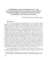
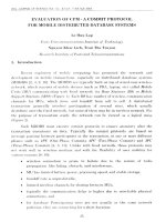
the metal and ceramic constituents respectively. Fig.1 describes the material characteristic of
Sigmoid FGM. According to the mentioned law, the Young modulus E (z ) and the thermal
expansion coefficient α (z ) can be expressed in the form
2 z + h k
h
, k ≥ 0,− ≤ z ≤ 0,
h
2
,
E ( z ) = E mV m + E cVc = E c + ( E m − E c )
k
−
2
z
+
h
h
,0 ≤ z ≤
h
2
6
2 z + h k
h
, k ≥ 0,− ≤ z ≤ 0,
2
α ( z ) = α mVm + α cVc = α c + (α m − α c ) h
k
− 2 z + h ,0 ≤ z ≤ h
h
2
(2)
the Poisson’s ratio ν is assumed to be constant.
Fig. 1. The material characteristic of Sigmoid Functionally Graded Material
3. Governing equations
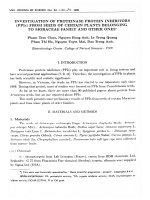
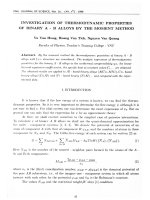
Consider a funtionally graded toroidal shell segment of thickness h, length L, which is
formed by rotation of a plane circular arc of radius R about an axis in the plane of the curve
as shown in Fig. 2. For the middle surface of a toroidal shell segment, from the figure:
r = a − R (1 − sin ϕ )
(3)
where a is the equator radius and ϕ is the angle between the axis of revolution and the
normal to the shell surface. For a sufficiently shallow toroidal shell in the region of the
equator of the torus, the angle ϕ is approximately equal to π/2, thus sin ϕ ≈ 1 ; cos ϕ ≈ 0 and
r =a [30]. The form of governing equation is simplified by putting:
dx 1 = Rd ϕ , dx2 = adθ .
(4)
7
The radius of arc R is positive with convex toroidal shell segment and negative with concave
toroidal shell segment
(a)
(b)
(c)
8
Fig. 2. Configuration and coordinate system of toroidal shell segments: (a) convex shell; (b)
concave shell and (c) toroidal shell segment on elastic foundation
The strains across the shell thickness at a distance z from the mid-surface are:
ε 1 = ε 10 − zχ1 ; ε 2 = ε 20 − zχ 2 ; γ 12 = γ 120 − 2 zχ 12 ,
(5)
where ε10 and ε 20 are normal strains, γ 120 is the shear strain at the middle surface of the shell
and χ ij are the curvatures.
According to the classical shell theory the strains at the middle surface and curvatures are
related to the displacement components u, v, w in the x1, x2, z coordinate directions as [35]:
2
∂v w 1 ∂w
∂u w 1 ∂w
; ε 20 =
− +
ε =
− +
∂x 2 a 2 ∂x 2
∂x1 R 2 ∂x1
0
1
χ2 =
2
2
∂ w
∂u
∂v ∂w ∂w
; γ 120 =
+
+
; χ1 = 2 ;
∂x 2 ∂x1 ∂x1 ∂x 2
∂x1
∂2w
∂ 2w
;
χ
=
.
12
∂x1∂x 2
∂x 22
(6)
From Eqs. (5) the strains must be satisfied in the deformation compatibility equation
2
∂ 2 ε 10 ∂ 2ε 20 ∂ 2γ 120
∂2w ∂2w ∂2w
∂ 2w ∂ 2w
+
−
=
−
−
+
−
.
∂x 22
∂x12 ∂x1∂x 2
R∂x 22 a∂x12 ∂x1 .∂x 2
∂x12 ∂x 22
(7)
The constitutive stress-strain equations by Hooke law for the shell material are given
E( z)
1
(ε 1 + νε 2 ) −
E ( z )α ( z )∆T ,
2
1 −ν
1 −ν
E ( z)
1
σ2 =
(ε 2 + νε 1 ) −
E ( z )α ( z )∆T ,
2
1 −ν
1 −ν
E(z)
σ 12 =
γ 12 ,
2(1 + ν )
σ1 =
(8)
where α (z) is the thermal expansion coefficient.
9
Intergrating the stress – strain equations and their moments through the thickness of the shell;
the expressions for force and moment resultants of a S-FGM toroidal shell segment are
obtained:
Φ
E1
E2
(ε 10 + νε 20 ) −
( χ1 + νχ 2 ) − a ,
2
2
1 −ν
1 −ν
1 −ν
E1
E2
Φ
N2 =
(ε 20 + νε 10 ) −
( χ 2 + νχ1 ) − a ,
2
2
1 −ν
1 −ν
1 −ν
E1
E
N 12 =
γ 120 − 2 χ 12 ,
2(1 + ν )
1 +ν
N1 =
Φb
,
1 −ν
1 −ν
1 −ν
E
Φ
E2
M2 =
(ε 20 + νε 10 ) − 3 2 ( χ 2 + νχ 1 ) − b ,
2
1 −ν
1 −ν
1 −ν
E
E2
M 12 =
γ 120 − 3 χ 12 ,
2(1 +ν )
1 +ν
M1 =
E2
2
(ε 10 +νε 20 ) −
E3
2
(9)
( χ 1 +νχ 2 ) −
(10)
where
( E m − Ec )h
, E2 = 0 ,
k +1
E h3
( E m − Ec )h 3
E3 = c +
,
12
2(k + 1)(k + 2)(k + 3)
E1 = E c h +
Φa =
(11)
h/ 2
h/2
−h / 2
−h / 2
∫ E ( z )α ( z ) ∆Tdz and Φ b =
∫ E ( z )α ( z ) ∆Tzdz .
The nonlinear equilibrium equations of a toroidal shell segment under lateral pressure q
(N/m2) based on the classical shell theory are given by [35]:
10
∂N 1 ∂N 12
+
= 0,
∂x1
∂x 2
∂N 12 ∂N 2
+
= 0,
∂x1
∂x2
∂2w ∂ 2w
∂2M1
∂ 2 M 12 ∂ 2 M 2
∂2w
∂2w
∂ 2 w N1 N 2
2 + 2 = 0 ,
+
2
+
+
N
+
2
N
+
N
+
+
+
q
−
K
w
+
K
1
12
2
1
2
∂x1∂x2
∂x1 ∂x2
R
a
∂x12
∂x22
∂x12
∂x22
∂x 2
∂x1
(12)
where K1 (N/m3) is linear stiffness of foundation, K2(N/m) is the shear modulus of the subgrade.
Considering the first two of Eqs. (12), a stress function may be defined as:
N1 =
∂2F
,
∂x 22
N2 =
∂2F
,
∂x12
N12 = −
∂2F
.
∂x1∂x 2
(13)
The reverse relations are obtained from Eqs. (9) regarding in this case E2 = 0
ε 10 =
Φ
1
( N 1 − νN 2 ) + a ,
E1
E1
ε 20 =
Φ
1
( N 2 − νN 1 ) + a ,
E1
E1
γ 120 =
2(1 + ν )
N 12 .
E1
(14)
Substituting Eqs. (14) into Eqs. (10) yields
E3
1
( χ1 + νχ 2 ) −
Φb,
2
1 −ν
(1 − ν )
E3
1
M2 = −
( χ 2 + νχ1 ) −
Φb ,
2
1 −ν
(1 − ν )
E3
M 12 = −
χ 12 .
(1 − ν )
M1 = −
(15)
The substitution of Eqs. (14) into the compatibility Eqs. (7) and Eqs. (15) into the third of
Eqs. (12), taking into account expressions (6) and (13), yields a system of equations
11
1
E1
∂4F
∂4F
∂4F
1 ∂2w 1 ∂2w ∂2w
4 +2 2 2 +
=
−
−
+
∂x
R ∂x 22 a ∂x12 ∂x1 ∂x 2
∂x1 ∂x 2 ∂x 24
1
2
∂2w ∂ 2w
− 2
,
∂x1 ∂x 22
(16)
∂2w ∂2w
E3 ∂ 4 w
∂4w
∂4w 1 ∂2 F 1 ∂2 F
∂2F ∂2w ∂2F ∂2w ∂2 F ∂2w
4 + 2 2 2 + 4 −
−
+2
− 2
− 2
+ K1w − K 2 2 + 2 − q = 0,
2
2
2
2
2
(1 −ν ) ∂x1
∂x1 ∂x2 ∂x2 R ∂x2 a ∂x1
∂x1∂x2 ∂x1∂x2 ∂x2 ∂x1 ∂x1 ∂x2
∂x1 ∂x2
(17)
Eqs. (16) and (17) are nonlinear governing equations used to investigate the nonlinear postbuckling of S-FGM toroidal shell segments surrounded by an elastic medium under lateral
pressure loads including temperature effects.
4. Nonlinear static buckling analysis
The S-FGM toroidal shell segment is assumed to be simply supported at its edges x1 = 0 and
x1 = L and subjected to lateral pressure uniformly distributed on the outer surface of shell.
Depending on the in-plane behavior at the edge, two cases of boundary conditions will be
considered.
Case 1: The edge is simply supported and freely movable (FM) in the axial direction. The
associated boundary conditions are:
w = 0, M1 = 0, N1 = 0, N12 = 0 at x1 = 0; L
(18)
Case 2: The edge is simply supported and immovable (IM) for this case the boundary
conditions are:
u = 0, w = 0, M1 = 0, N1 =N0, N12 = 0 at x1 = 0; L
(19)
where N0 is the fictitious compressive edge load rendering the edge immovable.
With the consideration of boundary conditions (18) and (19) the deflection of radial-loaded
shells can be expressed as following [24]:
12
w = W0 + W1 sin γ m x1 sin β n x 2 + W2 sin 2 γ m x1 ,
where γ m =
(20)
mπ
n
; β n = and m, n are the half waves numbers along x1-axis and waves
L
a
numbers along x2-axis, respectively. The first term of w in Eq. (20) represents the uniform
deflection of points belonging to two butt-ends x1 = 0 and x1 = L, the second term-a linear
buckling shape and the third-a nonlinear buckling shape.
It can be seen the simply supported boundary condition at x1 = 0 and x1 = L is fulfilled on the
average sense.
Substituting Eq. (20) into Eq. (16) yields:
W
W
W2
1 ∂4F
∂4F
∂4F W
4 + 2 2 2 + 4 = 1 β n2 + 1 γ m2 − W1W2 γ m2 β n2 sin γ m x1 sin β n x 2 + − 2 2 γ m2 − 1 γ m2 β n2 cos 2γ m x1
E1 ∂x1
a
a
2
∂x1 ∂x 2 ∂x 2 R
2
W
+ 1 γ m2 β n2 cos 2 β n x 2 + W1W 2γ m2 β n2 sin 3γ m x1 sin β n x 2 .
2
(21)
The general solution of this equation is given by:
F = f 1 sin γ m x1 sin β n x 2 + f 2 cos 2γ m x1 + f 3 cos 2β n x 2 + f 4 sin 3γ m x1 sin β n x 2 +
N0 2
x2
x 2 + σ oy h 1 ,
2
2
(22)
where σ oy is the negative average circumferential stress and
f1 =
E1 (β n2 / R + γ m2 / a)
E1γ m2 β n2
E1 β n2 2
E
W
−
W
W
;
f
=
W1 − 21 W2
1
1 2
2
2
2 2
2
2 2
2
(γ m + β n )
(γ m + β n )
32γ m
8γ m a
f3 =
E1γ m2 2
E1γ m2 β n2
W
;
f
=
W1W2
1
4
32β n2
(9γ m2 + β n2 ) 2
(23)
13
In order to set up a load-defection curve, first of all, substituting Eqs. (20) and (22) into
Eq. (17), then applying Galerkin’s method for the resulting equation in the ranges
0 ≤ x 2 ≤ 2πa and 0 ≤ x1 ≤ L , that are:
2πa L
∫ ∫ Rdx dx
1
2
= 0,
0 0
2πa L
∫ ∫ R sin γ
x sin β n x 2 dx1 dx 2 = 0,
m 1
0 0
2πa L
∫ ∫ R sin
2
γ m x1 dx1 dx 2 = 0,
0 0
where R is the left hand side of the resulting equation, we obtain the following
equations:
σ oy h
a
+
N0
K
− K 1W0 − 1 W2 + q = 0,
R
2
(24)
2
β n2 γ m2
E1
2
2 2
2
2
2
2
(γ m + β n ) D +
+
(γ 2 + β 2 ) 2 W1 + [ N 0 γ m + σ oy hβ n + K1 + K 2 (γ m + β n )]W1
R
a
m
n
β 2 γ 2 E γ 2β 2
E
β2
− E1 2 n + m 21 m 2n 2 + n W1W2 + 1 γ m4 + β n4 W13
a (γ m + β n )
4a
16
R
(
)
(25)
1
1
+ E1γ m4 β n4 2
+
W W 2 = 0,
2 2
2
2 2 1 2
(
γ
+
β
)
(
9
γ
+
β
)
m
n
m
n
β n2 γ m2
+
a
R
E1γ m2 β n2
E1 β n2 2
γ m4 β n4 E1 2
1
4
4
2
+
W
−
E
+
γ
β
1
W1 W2
m n 1
2
2 2
(γ + β 2 ) 2
8 a
(9γ m2 + β n2 ) 2
n
m
(γ m + β n )
E
K
− 2 N 0 γ m2 + 12 + 8γ m4 D + 2 K 2 γ m2 + 1 W2 = 0.
2
2a
where D =
(26)
E3
(1 − ν 2 )
14
Furthermore, the toroidal shell segments have to also satisfy the circumferential closed
condition [24] as:
L 2 πa
∫∫
0 0
L 2πa
∂v
dx1 dx 2 = ∫
∂x 2
0
∫
0
w 1 ∂w
ε 20 + −
a 2 ∂x 2
2
dx1 dx 2 = 0
Using Eqs. (13) (14) and (22), the integral becomes:
σ oy h
E1
−
ν
E1
N0 +
W0 W2 1 2 2
+
− W1 β n = 0.
a
2a 8
(27)
Solving Eqs. (24) (26) and (27) yields:
W12 = −
W0 =
( H 3 N 0W2 + H 4W2 )
,
H 1 + H 2W2
N
qa 2
+ 0
E1 H 10 H 10
a2
ν
+
E1 R E1
(28)
1 β n2 a ( H 3 N 0W2 + H 4W 2 ) K 1 a 2 1 W2
a +
+
,
−
−
H 1 + H 2W 2
2 H 10
8 H 10
2 E1
(29)
where
H1 =
E1γ m2 β n2
(γ m2 + β n2 ) 2
E γ 4β 4
E1γ m4 β n4
β n2 γ m2 E1 β n2
+
; H 2 = − 21 m 2n 2 −
;
+
a
8a
(γ m + β n )
(9γ m2 + β n2 ) 2
R
H 3 = −2γ m2 ; H 4 = −
E1
K
− 8γ m4 D − 2K 2 γ m2 − 1 .
2
2a
2
(30)
Substituting Eqs. (28) and (29) into Eq. (25) leads to
q=−
H 5 γ m2
aβ n2
H9 a2
H 3W2
H β 2 a
ν
H 8 + 9 n N 0
+ −
+
−
+ a +
H11 H 11 RH11 H10 H 11 E1 R E1 H 11 ( H 1 + H 2W2 )
8H 10
K a 2 1 H 9
H
H 4W2
H β 2 a
H
H 8 + 9 n W2 − 7 W22 ,
+ 1 +
− 6 +
8H10
H11
2 E1 2 H 10 H 11 H 11 H11 ( H1 + H 2W2 )
15
(31)
where
2
β2 γ2
E1
H 5 = (γ + β ) D + n + m
+ K 1 + K 2 (γ m2 + β n2 ) ;
2
2 2
R
a
(
γ
+
β
)
m
n
2
m
2
n
2
β 2 γ 2 E γ 2β 2
E γ 4β 4
E1γ m4 β n4
K
E β2
;
H 6 = −2 n + m 21 m 2n 2 + 1 aβ n2 − 1 n ; H 7 = 21 m 2n 2 +
a (γ m + β n )
2
4 a
(γ m + β n )
(9γ m2 + β n2 ) 2
R
E1 (γ m4 + β n4 )
K1a 2
H 9a 2
2
H8 =
; H 9 = K1 aβ n ; H 10 = 1 +
; H 11 =
− aβ n2 .
16
E1
E1 H 10
If W2 = 0, the nonlinear buckling shape will vanish, Eq. (31) becomes:
q=−
H 5 γ m2
aβ n2
H9 a2
ν
+ −
+
−
+
H 11 H 11 RH 11 H 10 H 11 E1 R E1
a N 0 .
(32)
Expression (31) is used to investiged the critical loads and to analyze the post-buckling loaddeflection curves of nonlinear buckling shape of FGM toroidal shell segments in elastic
medium while Eq. (32) is used to find critical loads in case linear buckling.
From Eq. (20), it is clearly that the maximal deflection of the shells
wmax = W0 + W1 + W 2
locates at x1 =
(33)
iL
jπR
; x2 =
, where i, j are odd integer numbers
2m
2n
Substituting Eqs. (28) (29) into Eq. (33) yields
16
wmax =
N a2
qa 2
ν
+ 0
+
E1 H 10 H 10 E1 R E1
1 β n2 a ( H 3 N 0W2 + H 4W2 ) K 1 a 2 1 W2
a +
+
−
−
8
H
H
+
H
W
2
E
2 H 10
10
1
2 2
1
(34)
( H N W + H 4W2 )
+ − 3 0 2
+ W2 .
H 1 + H 2W 2
Combining Eq. (31) and Eq. (34), the relation of postbuckling load - maximal deflection
curves of shells in parametrical form can be analyzed.
4.1.
Mechanical stability analysis
The simply supported S-FGM toroidal shell segments with free movable edge (that is, case 1)
are assumed to be subjected to lateral pressure q uniformly distributed on the outer surface of
the shell in the absence of temperature conditions. In this case N0 = 0 and Eqs. (31) and (34)
lead to
q=−
H 5 K1a 2 1 H 9
H
H β 2 a
H
H4
H 8 + 9 n W2 − 7 W22 ,
+
+
− 6 +
H 11 2E1
2 H 10 H 11 H 11 H 11 ( H 1 + H 2W2 )
8H 10
H 11
(35)
wmax =
qa 2
1 β n2 a H 4W2
−
E1 H 10 8 H 10 H 1 + H 2W2
K 1 a 2 1 W2
H 4W2
−
+
+ −
+ W2 .
2 H 10
H 1 + H 2W 2
2 E1
(36)
Eliminating W2 from two Eqs.(35) and (36) we can derive the postbuckling load-maximal
deflection curves q~wmax
By omitting the nonlinear buckling shape in Eq. (35), i.eW2= 0 we have
2
q=−
H5
H 11
β2 γ 2
E1
(γ + β ) D + n + m
+ K 1 + K 2 (γ m2 + β n2 )
2
2 2
a (γ m + β n )
R
=−
,
K 1 β n2 a 3
2
− aβ n
K1a 2
E1 1 +
E
1
2
m
2
n
2
(37)
17
from which the linear buckling load can be obtained.
4.2.
Thermomechanical stability analysis
The simply supported S-FGM toroidal shell segment with immovable edge (that is, case 2)
under simultaneous action of uniform external pressure q and thermal load is considered. The
condition expressing the immovability on the boundary edges, i.e u = 0 at x1 = 0; L is
fulfilled on the average sense as
L 2πa
∫∫
0 0
∂u
dx1 dx 2 = 0.
∂x1
Using Eqs. (6), (13) and (14) one can obtain the expression of
(38)
∂u
and then substituting the
∂x1
result into Eq. (38) gives:
N 0 νσ oy h Φ a W0 W2 W12γ m2 W22 γ m2
−
+
+
+
−
−
= 0.
E1
E1
E1
R 2R
8
4
(39)
Substituting Eqs. (27) (28) and (29) into Eq. (39) yields
1 ν 1 K νa a 2
K1νa 2 a γ m2
1
H 3 β n2W2
N0 1 + a + − 1 + νa
+
− + 2 H10
E1 R
R βn
E1 H10 8 H10 ( H1 + H 2W2 ) E1
E1 R R
+q
−
K1νa 2 a γ m2
ν
a 2 1 K1ν
H 4 β n2
−
a + H10 + W2
− + 2 H10
E1 H10 R E1
a
R βn
8 H10 ( H1 + H 2W2 ) E1
1 K1a 2 1 1 K1ν
+ −
H10 2 E1 2 R E1
1 K1νa γ m2W22 Φ a
−
a +
−
+
= 0.
4
E1
2 R 2 E1
(40)
Eq. (40) will be rewritten:
N0Ω(W2) + qH12 + W2Ψ(W2) −
γ m2 W22
4
+
Φa
= 0.
E1
(41)
18
where
H 12 =
a2
E1 H 10
1 K 1ν
ν
−
a + H 10 ,
E1
a
R
Ω(W2 ) =
K1νa 2 a γ m2
1
H 3 β n2W2
1 ν 1 K 1νa a 2
+ νa
+
− + 2 H 10 ,
1 + a + −
E1
R R
E1 R
R βn
E1 H 10 8 H 10 ( H 1 + H 2W2 ) E1
Ψ(W2 ) =
K1νa 2 a γ m2
H 4 β n2
1 K1a 2 1 1 K1ν
−
+
H
−
+ −
10
8H 10 ( H 1 + H 2W2 ) E1
R β n2
2 R E1
H 10 2E1
1 K1νa
a +
−
2R 2 E1
(42)
From Eq. (41) finding N0 and then putting the result into Eq. (31) we can obtain the equation
representing the post-buckling load-deflection curves of nonlinear buckling shape q(W2) of SFGM toroidal shell segments including temperature effect.
Otherwise, eliminating N0 form three equations (31), (34) and (41) one obtains the
parametrical equations determining post-buckling load-maximal deflection curves q~Wmax of
S-FGM toroidal shell segments in thermal environment.
In what follows, specific expressions of thermal parameter Φ a for thermal loads will be
determined.
Suppose that environment temperature is assumed to be uniformly raised from initial value
Ti at which the shell is thermal stress free, to final one Tf and temperature change
∆T = T f − Ti is independent to thickness variable. The thermal parameter Φ a can be
expressed in term of the ∆T due to Eq. (11) as
Φ a = P∆Th,
where P = Ecα c +
(43)
Ecα mc + Emcα c Emcα mc
+
, α mc = α m − α c and Emc = Em − Ec .
k +1
2k + 1
19
5.
Results and discussions
5.1.
Validation of the present study
The buckling behavior of a homogenous isotropic toroidal shell segment under uniform
lateral pressure is investigated. This was also considered earlier by Hutchinson [32] using the
Koiter’s general theory. Eq. (37) degenerates into a linear buckling load of isotropic toroidal
shell segments without elastic foundation. This coincides excellently with the classical linear
result reported by Hutchinson [32] as follows:
2
2 nL 2 a
m +
2
2
2
3
2
2
π
a
R
π πa 2 nL
Eh
12 z
qa =
m
+
+
2 2
π4
12(1 −ν 2 ) L2 nL
πa
nL
2
m +
πa
where z = 1 − ν 2
5.2.
L2
ah
Results of nonlinear buckling of S-FGM toroidal shell segments
To illustrate the proposed approach we consider Sigmoid-Functionally graded toroidal
shell segments that consist of Aluminum and Alumina with the following properties:
Em = 70 × 10 9 N / m 2 ; α m = 23 ×10 −6 0C −1
Ec = 380 × 10 9 N / m 2 ; α c = 7.4 × 10 −6 0C −1
where Poison’s ratio is chosen to be 0.3
The effects of material and geometric parameters, elastic foundation and thermal
environment on the non-linear response of Sigmoid-Functionally graded material (S-FGM)
20
toroidal shell segments under uniform lateral pressure are considered in Figs. 3 – 9. It is noted
that in all figures Wmax/h denotes the dimensionless maximum deflection of the shell.
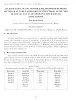
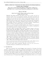
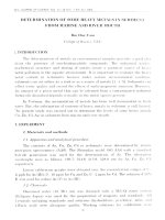
The effects of the R/h on q~Wmax/h post-buckling curves of FGM convex and concave
toroidal shell segment on elastic medium (K1 = 2.5×10⁸ N/m3, K2 = 5×10⁵ N/m) are described
in Figs. 3 and 4, respectively.
As can be seen, the load-deflection curves of S-FGM convex toroidal shell segment
become lower, whereas those of S-FGM concave shell become higher when increasing the
ratio R/h. The load bearing capability of convex toroidal shells is considerably enhanced as
ratio decreases, but conversely for concave ones.
Table 1 shows the comparison of the critical buckling loads of two types S-FGM and PFGM toroidal shells. As can be observed, with the same geometrical parameters, the critical
buckling loads of the S-FGM with ceramic-metal-ceramic layers are higher than those of the
P-FGM with metal-ceramic layers.
21
Fig.3. Effect of R/h ratio on the post-buckling curves of S-FGM convex shell on elastic
foundation
Fig.4. Effect of R/h ratio on the post-buckling curves of S-FGM concave shell on elastic
foundation
Table 1. Comparison of the critical buckling loads of two types S-FGM and P-FGM shells
qcr (×107Pa) (m, n) = (1, 5)
R/h = 300
Types
R/h = 400
R/h = -300
R/h = -400
Upper
Lower
Upper
Lower
Upper critical
Lower
Upper critical
Lower
critical load
critical load
critical load
critical load
load
critical load
load
critical load
calculated
calculated
calculated
calculated
calculated by
calculated
calculated by
calculated
by Eq. (37)
by Eq.
by Eq. (37)
by Eq.
Eq. (37)
by Eq.
Eq. (37)
by Eq.
(35)&(36)
S-FGM
qcr (×107Pa) (m, n) = (1, 2)
2.7218
2.4404
(35)&(36)
2.1828
2.0969
(35)&(36)
8.9610
8.6021
(35)&(36)
10.257
9.1613
22
P-FGM
2.7205
2.4381
2.1815
2.0951
8.9591
8.5993
10.255
9.1579
The effect of L/R ratio on the critical buckling load of S-FGM convex and concave shell
on Pasternak foundation is illustrated in Table 2 and Table 3, respectively. The data of
problem: h = 0.01m; a = 100h; R = ±500h.
Table 2. Effect of L/R ratio on the critical buckling load (MPa) of S-FGM convex shell on
elastic foundation with various modes
(m =1) n
L/R
1.5
2
2.5
3
4
24.758
24.511
24.398
24.337
5
15.928
15.827
15.780
15.755
6
11.192
11.143
11.120
11.108
7
8.3569
8.3302
8.3179
8.3112
8
6.5251
6.5093
6.5020
6.4981
9
5.2730
5.2630
5.2584
5.2559
Table 3. Effect of L/R ratio on the critical buckling load (MPa) of S-FGM concave shell on
elastic foundation with various modes
(m =1) n
L/R
-1.5
-2
-2.5
-3
4
23.417
23.750
23.908
23.996
5
15.374
15.513
15.579
15.615
6
10.924
10.991
11.023
11.040
23
7
8.2117
8.2483
8.2654
8.2748
8
6.4399
6.4613
6.4713
6.4767
9
5.2197
5.2330
5.2392
5.2426
It is observed that when the L/R ratio increases, the critical buckling loads of S-FGM
convex shell decrease while ones of S-FGM concave shell increase. It means that the critical
loads of shorter convex shells are greater than those of longer ones while the concave shells
are completely on the contrary. For instance, when L/R ratio increases from 1.5 to 3, the
critical loads slightly fall by about 0.3 ~ 1.7% for the convex shell and increase by about 0.4
~ 2.5% for the concave shell.
Fig. 5 illustrates the effect of L/a ratio on the post-buckling curves of S-FGM convex
shell on elastic foundation. It is shown that the non-linear response of toroidal shell segment
is sensitive with change of L/a ratio characterizing the shallowness of toroidal shell segment.
Specifically, the enhancement of the upper buckling loads and the load carrying capacity in
small range of deflection as L/a decrease is followed by a very severe snap-through behavior.
In other words, in spite of possessing higher limit buckling loads, the toroidal shells with
smaller ratio L/a exhibit a very unstable response from the post-buckling point of view.
24