DSpace at VNU: Vectored DSL: Potential, Implementation Issues and Challenges
Bạn đang xem bản rút gọn của tài liệu. Xem và tải ngay bản đầy đủ của tài liệu tại đây (1.35 MB, 17 trang )
This article has been accepted for inclusion in a future issue of this journal. Content is final as presented, with the exception of pagination.
IEEE COMMUNICATIONS SURVEYS & TUTORIALS, ACCEPTED FOR PUBLICATION
1
Vectored DSL:
Potential, Implementation Issues and Challenges
Christopher Leung, Sean Huberman, Khuong Ho-Van, and Tho Le-Ngoc
Abstract—This paper investigates specific techniques suitable
for Vectored DSL, their performance, complexity and practical
implementation. More specifically, various Vectored DSL techniques for both upstream and downstream transmission are
discussed, including the Tomlinson-Harashima Pre-coder (THP),
Diagonalizing Pre-coder (DP), Zero-Forcing (ZF) canceller, and
Decision-Feedback (DF) canceller. A thorough discussion on some
of the practical implementation aspects of Vectored DSL is
provided. In particular, various implementation challenges are
discussed, including computational load, memory storage, line
management, partial crosstalk cancellation, and the effect of
imperfect channel knowledge. As well, the potential gains and
challenges of combining Phantom DSL and Vectored DSL are
also discussed. Illustrative examples are provided based on both
measured data and channel models to compare the various
Vectored DSL techniques and their practical implementation
challenges.
Index Terms—Digital Subscriber Line (DSL), Vectored DSL,
pre-coding, interference cancellation.
I. I NTRODUCTION
D
IGITAL Subscriber Line (DSL) service providers are
in fierce competition with cable companies to provide
services such as multicast/unicast video, HDTV, and 3D TV.
The demand for data-intensive services is on the rise. In
order to support more sophisticated multimedia services and
compete with cable companies, DSL is pushing for higher
data-rates.
One solution for achieving higher data-rates involves running optical fiber wire directly from the Central Office (CO) to
every Customers Premise (CP), known as Fiber-To-The-Home
(FTTH). Deploying FTTH can require costly investments
especially in buried-cable areas. As such, service providers,
who have already heavily invested in DSL technology and in
their copper-wire network, wish to make use of hybrid optical
fiber and copper wire networks to meet the data-rate demands
at a lower cost.
The family of hybrid optical fiber and copper wire networks
are referred to as FTTx networks. The type of FTTx network
Manuscript received May 15, 2012; revised October 4, 2012. This work was
supported in part by the Natural Sciences and Engineering Research Council
of Canada and Bell Canada through the Industrial Research Chair program.
Moreover, some of the authors were funded by the Fonds qu´ebecois de la
recherche sur la nature et les technologies.
C.Leung, S. Huberman and T. Le-Ngoc are with the Department
of Electrical and Computer Engineering, McGill University, 3480
University Street, Montreal, Quebec, Canada, H3A 2A7 (e-mails:
, , ).
K. Ho-Van is with the Department of Telecommunications Engineering, Ho
Chi Minh City University of Technology, 268 Ly Thuong Kiet Street, District
10, Ho Chi Minh City, Viet Nam (e-mail: ).
Digital Object Identifier 10.1109/SURV.2013.011413.00098
used depends on the range of copper line lengths in the system.
For example, Fiber-To-The-Node (FTTN) uses optical fiber
wire to transmit information from the CO to a node and then
uses copper wire to transmit from the node to every CP in its
distribution area. In North America, FTTN loops can contain
loop lengths up to 1.5 km, but FTTN loop lengths of up to 500
m are more common. Similarly, Fiber-To-The-Curb (FTTC)
uses optical fiber wire to transmit information from the CO to
a small DSL Access Multiplexer (DSLAM) which typically
contains loop lengths of up to 500 m [1]. Furthermore, FiberTo-The-Building (FTTB) uses optical fiber wire to transmit
information from the CO to a building.
DSL systems transmit data to and from various CPs over
bundles of copper wire encapsulated within a cable binder. The
interference between neighbouring lines is known as crosstalk.
Crosstalk is the limiting factor in the achievable data-rates of
DSL systems. As such, to improve the achievable data-rates,
the crosstalk interference must be reduced or removed entirely.
There are two types of crosstalk: Near-End-Crosstalk
(NEXT) and Far-End-Crosstalk (FEXT). NEXT is the
crosstalk seen by neighbouring lines at the transmitter side
and FEXT is the crosstalk seen by neighbouring lines at the
receiver side. DSL uses Frequency-Division Duplexing (FDD)
in order to remove the NEXT interference. As such, the only
significant form of system crosstalk is the FEXT interference.
Hence, higher data-rates can be achieved by minimizing or
even removing the FEXT interference.
Spectrum Management (SM) techniques can be employed
to achieve this goal. The most basic form of SM is known
as Static SM (SSM). SSM implements static spectral masks
based on a worst-case scenario assumption for all users. This
leads to an inefficient use of the frequency spectrum whenever
the scenario is not the worst-case and consequently leads to
highly sub-optimal performance.
Dynamic SM (DSM) is a wide field which looks to adaptively apply different spectral masks for each user with the intent of maximizing the throughput of the overall system. DSM
allows for a far more efficient use of the spectrum than SSM
does. There are three levels of DSM [2]; DSM level 1 performs
spectrum balancing independently from line to line to mitigate
crosstalk, DSM Level 2 performs spectrum balancing jointly
across multiple lines to mitigate crosstalk, and DSM Level
3 performs signal-level coordination to remove crosstalk. A
detailed survey of DSM Levels 1 and 2 is provided in [3].
DSM Level 3 applies Vectored DSL to effectively remove
crosstalk. Vectored DSL makes use of pre-coding in downstream transmission and makes use of Multi-User Detection
(MUD) interference cancellation in upstream transmission.
1553-877X/13/$31.00 c 2013 IEEE
This article has been accepted for inclusion in a future issue of this journal. Content is final as presented, with the exception of pagination.
2
IEEE COMMUNICATIONS SURVEYS & TUTORIALS, ACCEPTED FOR PUBLICATION
DSM Level 3 can also incorporate DSM Levels 1 and 2 in
order to mitigate any crosstalk which is not removed (e.g.,
due to imperfect channel knowledge or to crosstalk from nonvectored lines).
In the early 21st century, a method using phantom circuitry
was proposed to transmit up to three channels worth of data
over two physical twisted-pair wires [4]. The phantom circuit
can significantly increase the capacity of the system; however,
it also significantly increases the crosstalk in the system which
makes it more difficult to achieve the capacity. Due to the
increased crosstalk, the phantom circuit (applied to DSL)
was abandoned, until the recent advances in Vectored DSL
technology [4].
Applying the phantom circuit to DSL technology is known
as Phantom DSL. By combining Phantom DSL with the
crosstalk mitigation of Vectored DSL, the capacity gains of
Phantom DSL can be achieved without the increased crosstalk
(i.e., Vectored DSL can remove the original crosstalk, as well
as the additional crosstalk generated by the phantom process)
[5].
While Phantom DSL promises increased capacity, it also
provides some challenges from an implementation perspective. More specifically, Phantom DSL requires more sophisticated modems and chipsets, which are capable of combining/recovering the three-channels worth of data over two
physical channels. As well, the multiple-line requirement for
Phantom DSL may require infrastructure changes in locations
where consumers are only provided a single DSL line; however, it is common for two twisted-pair copper lines to service
a single dwelling, allowing for a third “virtual” pair. Finally,
thus far, Phantom DSL results have only been obtained within
a lab-setting.
The rest of this paper is organized as follows. Section II
discusses the xDSL environment. Section III presents some
downstream and upstream vectored transmission techniques.
Section IV provides some numerical results to demonstrate the
performance gains of Vectored DSL. Section V presents some
issues and solutions in implementing Vectored DSL. Section
VI investigates the use of partial cancellation techniques, in
order to reduce the computational complexity of Vectored
DSL. Section VII shows the effect of channel estimation
error on the performance of Vectored DSL. Section VIII
gives an overview of Phantom DSL and summarizes some
preliminary in-lab test results. Finally, Section IX provides
some concluding remarks.
Notation: In this paper, non-bold variables denote scalars
(e.g., a), lower-case bold variables denote vectors (e.g., a), and
upper-case bold variables denote matrices (e.g., A). [A](n,m)
refers to the (n, m)-th element of matrix A. Similarly, [A](n, )
refers to the vector whose elements are given by the n-th row
of matrix A. A† refers to the conjugate transpose of matrix A.
diag(A) refers to the matrix of all-zeros except with diagonal
elements identical to A.
II. V ECTORED DSL AND THE X DSL E NVIRONMENT
xDSL is a family of technologies which make use of
twisted-pair copper telephone wires to transmit digital data
[6] [7]. xDSL operates on the same physical twisted-pair
copper wiring as Plain Old Telephone Service (POTS) by
using the higher frequency bands, while POTS is restricted
to the lower frequency band (less than 4 kHz). Different
frequency bands are used for different DSL technologies.
For example, in Asymmetric Digital Subscriber Line (ADSL)
the maximum frequency used is 1.1 MHz, in ADSL2plus
the maximum frequency used is 12 MHz, and in Very high
bit-rate DSL (VDSL) the maximum frequency used is 30
MHz. There are dedicated frequency bands for upstream and
downstream transmission. For most DSL technologies, the
frequency bandwidth is allocated asymmetrically where a
larger portion is allocated for downstream transmission than
for upstream transmission.
xDSL technology uses Discrete Multi-Tone (DMT) transmission, a scheme which is similar to Orthogonal FrequencyDivision Multiplexing (OFDM). DMT is a transmission technique which divides the available frequency spectrum into
many sub-channels or frequency tones. The main difference
between DMT and OFDM transmission is that DMT is also
capable of optimizing the bit and energy distribution over
the sub-channels (e.g., channel partitioning or bit-loading)
[6]. The basic idea is to transmit the data in parallel over
each frequency tone (note that some frequency tones might
transmit no data, while others can transmit a lot of data). More
information on DMT transmission and the xDSL environment
can be found in [3].
A. System Model
Consider a DSL network with a set of users (modems)
N = {1, . . . , N } and frequency tones (sub-carriers) K =
{1, . . . , K}. Using synchronous DMT modulation, there is
no Inter-Carrier Interference (ICI) and transmissions can be
modeled independently on each tone k as follows:
yk = Hk xk + zk .
(1)
The vector xk
[x1k , . . . , xnk ]T contains the transmitted
signals for all users on frequency tone k, where xnk is the
transmitted signal by user n on frequency tone k. Similarly,
yk [yk1 , . . . , ykN ]T and zk [zk1 , . . . , zkN ]T where ykn is the
received signal for user n on frequency tone k. Likewise, zkn
is the additive noise for user n on frequency tone k which
contains thermal noise, alien crosstalk and radio frequency
interference. Hk is an N × N matrix such that [Hk ](n,m) is
the channel gain from transmitter m to receiver n on frequency
tone k, and is defined as hn,m
. The transmit PSD of user n
k
on frequency tone k is defined as snk E{|xnk |2 }/Δf , where
E{·} denotes expected value, and Δf denotes the frequency
tone spacing.
When the number of users is large enough, the interference
is well approximated by a Gaussian distributed random variable, and hence the achievable bit-rate of user n on frequency
tone k is defined as:
bnk
log2 1 +
1
Γ
2 n
|hn,n
k | sk
,
n,m 2 m
| sk + σkn
m=n |hk
where Γ is the Signal to Noise Ratio (SNR) gap which is a
function of the desired Bit Error Rate (BER), coding gain,
and noise margin [7], and σkn
E{|zkn |2 }/Δf is the noise
This article has been accepted for inclusion in a future issue of this journal. Content is final as presented, with the exception of pagination.
LEUNG et al.: VECTORED DSL: POTENTIAL, IMPLEMENTATION ISSUES AND CHALLENGES
power density of user n on frequency tone k. The achievable
data-rate for user n is therefore Rn = fs k bnk , where fs is
the DMT symbol rate.
There are two types of physical power constraints imposed
on the transmitted signals for each user. The first constraint is
a total power constraint (over all frequency tones for a single
user), denoted by P n for user n. The second constraint is a
per-frequency tone maximum power constraint, referred to as
a spectral mask. The spectral mask constraint for user n on
frequency tone k is denoted by sn,mask
. The power constraints
k
can be summarized as follows:
snk ≤ P n for all n,
Δf
k
for all n, k.
0 ≤ snk ≤ sn,mask
k
(2)
B. xDSL Network Configurations
Fig. 1 shows a typical xDSL network. As shown in Fig. 1,
the twisted-pair copper wire is run through binders. There
are sections of the network where all the lines belong to
a particular CO or DSLAM. There are also sections where
the binder is shared between the CO and a DSLAM. Optical
fiber wire is run to a CO and/or to DSLAMs. Twisted-pair
copper wire is run from the CO and/or the DSLAMs to various
Junction Wire Interfaces (JWIs). Twisted-pair copper wire is
then run from the JWIs to the CPs and/or office buildings.
For this particular network (e.g., binder type B), due to the
long length of the CO relative to the DSLAM, the DSLAM
lines can cause severe crosstalk to the CO users (this is known
as the near-far problem). Note that type B binders can also
correspond to binders shared by lines from two DSLAMs. It is
worthwhile to note that loops where the CO directly connects
to a JWI and/or CPs (i.e., binder type A) are becoming less and
less common. This is due to the fact that channel attenuation
increases with line length, especially at higher frequencies.
As such, it is far more difficult to achieve higher data-rates
for longer lines. Lines corresponding to binder type A are
often very long in length (e.g., on the order of kilometers). As
such, network topologies similar to binder type C (i.e., FTTx)
are becoming increasingly popular since they are capable of
achieving higher data-rates.
The two types of network configurations corresponding to
binders B and C, as shown in Fig. 1, will be discussed in more
details in Sections II-B1 and II-B2, respectively.
1) Binders With Multiple Disturbing Loops: The first
binder configuration type is where there are multiple loops
sharing a binder. Binder B in Fig. 1 is an example of this
type of binder configuration. Binder B is shared between the
loop from the CO to the JWI and CPs at the top right of the
diagram and the loop between a DSLAM and the JWI and
CPs in the middle of the diagram.
One of the challenges of managing networks involving
binders with multiple disturbing loops is known as the nearfar problem. The near-far problem is caused by the fact that
for twisted-copper pair wires, the attenuation increases with
length. Hence, when the receivers from one bundle of lines
is in close proximity to the transmitters of another bundle,
they receive large amounts of crosstalk. More specifically, for
3
binder B in Fig. 1, for downstream transmission, the DSLAM
lines will cause strong crosstalk to the CO lines.
Another challenge of binders with multiple disturbing loops
is that from a network operator point-of-view, it is far more
challenging to apply coordinated vectored spectrum management since the lines are not all co-located. For such
scenarios, vectored spectrum management can be applied to
each disturbing loop separately treating the crosstalk from
other loops as background noise.
While such binder configurations are still quite common
in practice, in recent years, the focus has been on binders
with co-located lines. Co-located binder configurations will
be discussed in Section II-B2.
2) Binders With Co-located Lines: The second binder configuration type is where all the lines are co-located at either
the transmitter or the receiver. This corresponds to binder C
in Fig. 1. For this network binder configuration, optical fiber
wire is run to a node (e.g., DSLAM) and then twisted-pair
copper wire is run to a JWI and the CPs. Note that while
Fig. 1 shows binder C servicing a building, this binder type
can also service various CPs within a neighborhood.
There are several benefits of binders with co-located lines
from a network operator point-of-view. One of the main
advantages is that such networks do not suffer as drastically
from the near-far problem described in Section II-B1; however,
it can still cause significant performance degradation if the
crosstalk is not properly managed. Another benefit of binders
with co-located lines is that such networks are well-suited
for vectored spectrum management since all lines are colocated at either the transmitter or receiver, making joint signal
processing simpler.
The emergence of FTTx networks has molded the binder
topologies of DSL systems. In particular, as optical fiber runs
closer to each CP, there is less of a requirement for DSLAMs
located at geographically separate locations to share a binder.
Moreover, for FTTN, FTTC and FTTB networks, it is far more
common to deploy a single DSLAM (the size of which may
vary) to service the customers in its distribution area rather
than to have multiple DSLAMs sharing a binder. Hence, in
recent years, much interest in binders corresponding to binder
C has developed, since they are becoming increasingly more
popular from a practical perspective.
C. Channel Knowledge Availability
DSL systems consist of twisted-pair copper wires in static
cable binders and typically, do not move; hence, the DSL channel is considered very slow time-varying. As such, the DSL
channel is assumed to be time-invariant if new measurements
are taken often enough. Hence, Vectored DSL assumes full
channel knowledge. Full channel knowledge can be gained
through the use of loop testing. There are two types of DSL
loop tests: Single Ended Loop Test (SELT) and Double Ended
Loop Test (DELT).
SELT measurements are initiated by the DSLAM without
using the CP Equipment (CPE). More specifically, SELT measurements provide loop qualifications, such as the wire gauge
and the length of the loop. Since SELT measurements do not
require a CPE, they are often used to preemptively measure
This article has been accepted for inclusion in a future issue of this journal. Content is final as presented, with the exception of pagination.
4
IEEE COMMUNICATIONS SURVEYS & TUTORIALS, ACCEPTED FOR PUBLICATION
Central Office
A
B
DSLAM
Fiber Links
JWI:
Junction Wire Interface
DSLAM:
Digital Subscriber Line
Access Multiplexer
DSLAM
C
Fiber Links
Fig. 1.
Example of a typical xDSL Network.
the loop characteristics prior to installing the CPE. SELT
measurements can also provide the direct channel attenuation
and the background noise present on the line.
DELT measurements are initiated by the DSLAM but
require coordination with the CPE. As such, DELT measurements can provide more detailed on-the-fly measurements
of the loop characteristics; however, they require compatible
CPEs. DELT measurements can provide full channel knowledge, as well as the background noise for all lines in both the
upstream and downstream directions.
SELT and DELT measurements can be combined to provide
the best results for service providers [8]. SELT is more useful
than DELT during the pre-installation phase, while DELT is
more useful once the CPE is connected [8]. Once the CPE
is connected, SELT measurements can still be useful when
locating line faults in situations where the line conditions are
too poor for DELT.
D. MIMO Transmission: Downstream vs. Upstream
Vectored DSL transmission makes use of concepts originally developed for Multiple Input Multiple Output (MIMO)
systems [9]. A wireless MIMO system consists of NT transmit
antennas and NR receive antennas, where NT and NR are
not necessarily equal. As well, for a wireless MIMO system,
all the NT transmit antenna are co-located and all the NR
received antennas are co-located. Hence, for a wireless MIMO
system, pre-coding and/or interference cancellation (using
MUD) can be performed. MIMO DSL transmission differs
from wireless MIMO systems in the following ways. First,
NT = NR since each “antenna” corresponds to the end of
a twisted-pair copper wire. Second, MIMO DSL systems are
typically not co-located at both ends. Typically, MIMO DSL
systems are co-located at one end or can be grouped into
clusters of lines which are each co-located at one end (e.g.,
corresponding to a multi-user MIMO wireless system).
ADSL and VDSL transmission makes use of FDD, where
there are separate bandwidths for upstream and downstream
transmission and, hence, the two transmission cases can be
dealt with independently. Fig. 2(a) shows how upstream
vectored transmission applies to DSL networks. Since all
the receivers are co-located and full channel knowledge is
assumed, the crosstalk can be mitigated by MUD interference cancelling. Similarly, Fig. 2(b) shows how downstream
vectored transmission applies to DSL networks. Since all
the transmitters are co-located and full channel knowledge is
assumed, the signals can be pre-distorted using pre-coding so
that they arrive at each CP crosstalk-free.
E. Multi-Segment Problems
There are several multi-segment issues with regards to
Vectored DSL, including vector clusters, the differences between inter-crosstalk and intra-crosstalk, and alien-crosstalk
generated from mixed xDSL networks (e.g., some ADSL
lines and some VDSL2 lines). The multi-segment issues listed
above will be discussed in what follows.
Vector clusters refers to implementing vectoring over a
subset of the lines (or several subsets of lines). For example,
if a DSLAM is servicing 192 customers, rather than applying
vectoring across all 192 lines, it might be more computationally efficient to cluster the customers into four groups of
48 lines and apply vectoring to each cluster separately. As
such, the intra-crosstalk refers to crosstalk within the particular
cluster and inter-crosstalk refers to the crosstalk from one
cluster to another.
Inter-crosstalk and intra-crosstalk also arise whenever
binders have multiple disturbing loops as discussed in Section
II-B1 and shown in binder B of Fig. 1. In particular, the CO
and DSLAM represent two vector clusters. Also note that it is
possible that both the CO and DSLAM could apply vector
clustering on their respective lines resulting in additional
vector clusters.
The effects of intra-crosstalk can be removed using vectoring; however, the effects of inter-crosstalk cannot be removed
by vectoring, instead, the inter-crosstalk must be mitigated
using spectrum management techniques (i.e., DSM levels 1
and 2). A survey of spectrum management techniques is
given in [3]. Note that inter-crosstalk refers to crosstalk from
This article has been accepted for inclusion in a future issue of this journal. Content is final as presented, with the exception of pagination.
LEUNG et al.: VECTORED DSL: POTENTIAL, IMPLEMENTATION ISSUES AND CHALLENGES
5
(a) Upstream
(b) Downstream
Fig. 2.
Vectored DSL transmission.
lines that the network operator has control of and can apply
spectrum management to.
Similar to inter-crosstalk, is crosstalk generated from scenarios where there are mixed xDSL networks (e.g., some
ADSL and some VDSL2 lines). Such scenarios typically arise
when different service providers are sharing a binder and
as such neither one has control over the other’s lines. For
such scenarios, the crosstalk generated is referred to as aliencrosstalk and it is treated as background noise.
III. V ECTORED T RANSMISSION
Vectored transmission for DSL can be grouped into three
main methods: downstream transmission, upstream transmission, and joint transmitter-receiver transmission. In the joint
transmitter-receiver transmission, pre-coding and cancellation
can be performed at the transmitter and receiver sides. This
transmission style is only practical in cases where both the
transmitter and receiver are co-located. On the other hand,
as discussed in Section II-D, customers are not usually colocated. In this case, pre-coding at the transmitter is appropriate for downstream transmission and cancellation at the
receiver is appropriate for upstream transmission.
A. Downstream Transmission
The network configuration in downstream DSL transmission
makes it often impossible for interference cancellation to
occur at the receiver side. However, since the signals are
transmitted from the same location, pre-coding can still be
applied to pre-distort so that the signals arriving at the CPEs
are crosstalk-free. This section presents the two main methods
for applying vectoring in downstream transmission: the ZeroForcing (ZF) pre-coder [10], and the Tomlinson-Harashima
Pre-coder (THP) [11].
1) Zero-Forcing: Unlike the THP, the ZF method is a rather
simplistic linear pre-coder that uses the channel inverse for
pre-coding. Under this method, the resulting received signal
is given by
˜ k ) + zk .
yk = Hk (H−1
(3)
k x
It is evident that the ZF method has the potential to predistort the signal such that the signal is interference free when
it arrives at the receiver end. However, there is the possibility
that applying the inverse as the pre-coder can lead to large
transmit power increases and can violate the transmit power
or spectral mask constraints, especially if the channel matrix
is ill-conditioned. Yet, [12] showed that in cases where the
transmitters are co-located, the channel matrix is row-wise
diagonal dominant which leads to a near-optimal ZF method.
This Row-Wise Diagonal Dominance (RWDD) stems from the
fact that the crosstalk signal transmitted from one line to another to propagate through the full length of the disturber’s line
just like the direct signal. Thus, both the direct and crosstalk
signals travel the same distance but the crosstalk signals are
being additionally attenuated by the insulation between cables.
Hence, the diagonal element, [Hk ](n,n) , dominates the other
elements on the same row, [Hk ](n,m) .
We established previously that the ZF method can increase
the total transmit power. In a similar manner, the ZF method
can also increase the PSD. However, there exists an upper
bound on the allowable PSD known as the PSD mask. In order
to guarantee that the PSD mask remains intact, [12] proposed
to use a scaling factor on the pre-coding matrix. The scaling
factor, βk , ensures that any PSD-mask-compliant input to the
pre-coder will remain compliant once pre-coded. The scaling
factor for each user is obtained by satisfying the following
constraint:
sn,mask
> E |xnk |2
k
=E
=
1
βkn
1
= n
βk
1
[H−1
˜nk
k ](n, ) x
βkn
2
[H−1
xnk |2
k ](n,m) E |˜
2
m∈N
[H−1
˜n,mask
.
k
k ](n,m) s
2
m∈N
−1
2
Therefore,
=
m∈N |[Hk ](n,m) | . However, since the
scaling factor must be identical for each user, the final scaling
βkn
This article has been accepted for inclusion in a future issue of this journal. Content is final as presented, with the exception of pagination.
6
IEEE COMMUNICATIONS SURVEYS & TUTORIALS, ACCEPTED FOR PUBLICATION
The second step of the THP is to find the values of
x˜nk corresponding to crosstalk-free transmission for all users.
Hence, it is required that the following equality be satisfied:
factor is selected as the largest among all users:
βk
max βkn .
n
−1
The resulting pre-coder is H−1
k βk and the effective received
signal vector is:
1
˜ k + zk .
yk =
x
(4)
βk
The effective channel gain in (4) is the same for all users and
depends on the worse βkn . Hence, [12] further proposed the
Diagonalizing Pre-coder (DP).
The DP has the form:
1 −1
yk = Hk
H diag(Hk )˜
xk + zk .
βk k
The corresponding scaling factor for the DP is given by:
n
⎢
⎣
rk1,1
0
⎡
⎤ rk1,1
x
˜1k
⎢ 1,2
⎥⎢ .. ⎥ ⎢ rk
..
⎦⎣ . ⎦=⎢ ..
.
⎣ .
N,N
x
˜N
rk
k
rk1,N
0
⎤⎡
= log2
2 n
|hn,n
˜k
k | s
1+
.
n
diag 2
σ
Γ(βk )
k
n−1
xˆnk = modsn,mask
k
(5)
2) Tomlinson-Harashima pre-coder: The THP method for
vectoring is based on its original application for channel
equalization developed independently by Tomlinson [13] and
Harashima [14]. At the transmitter, it is a two-step non-linear
˜ k , is converted into an
pre-coder. The input of the THP, x
intermediate variable defined as (xk )int , which is used to
generate the true transmitted signal, xk . The first step begins
by taking the QR decomposing of the complex channel such
that:
H†k = Qk Rk ,
where Qk is a unitary matrix and Rk is an upper triangular
matrix. By setting the pre-coder matrix to Qk , the received
signal can be modeled as
yk = Hk (Qk (xk )int ) + zk
= (Qk Rk )† Qk (xk )int + zk
= R†k (xk )int + zk .
⎤
⎡ 1 int ⎤
⎥ (xk )
⎥⎢ .. ⎥
⎥⎣ . ⎦ .
⎦ N int
(xk )
N,N
0
0
..
.
rk2,N · · · rk
(xnk )int = modsn,mask x
˜nk −
The effective bit-rate using the DP is given by:
1
..
.
···
···
..
.
rkm,n m int
,
(x )
rn,n k
m=1 k
√
√
M /2
where modM [a] a − M a+√M
. The process can be
easily transformed for the complex constellation case.
Similarly, at the receiver, a second modulo operation is
applied to estimate the transmitted symbol as follows:
m∈N
The effective received signal vector is therefore given by:
1
xk + zk .
yk = diag diag(Hk )˜
βk
bnk
0
rk2,2
In order to ensure the spectral mask constraint is satisfied
after pre-coding, (xnk )int should be set as [11] when using
real-valued constellations:
k
m,m 2
|[H−1
| .
k ](n,m) hk
βkdiag = max
⎡
(6)
The first step of the THP method effectively transforms the
transmission channel into the lower triangular matrix R† in
int
(7). It can be easily seen that ykn = nm=1 [R†k ](n,m) (xm
+
k )
n
zk . Hence, user n = 1 transmits crosstalk-free and every other
user n = 2, . . . , N experiences crosstalk from users 1, . . . , n−
1, respectively. The second step of the THP takes advantage
of the fact that with the transmitted signal of user n = 1
known, the crosstalk induced from that user to other users
is also known and the transmitted signals of users 2, . . . , N
can be recursively pre-distorted. Once the recursive process is
completed, each user experiences crosstalk-free transmission.
⎡ 1,1
⎤
rk
0
···
0
⎢ r1,2 r2,2 · · ·
0 ⎥
k
⎢ k
⎥
†
Rk = ⎢ .
(7)
.. ⎥
.
.
..
..
⎣ ..
. ⎦
rk1,N rk2,N · · · rkN,N
ykn
zkn
˜nk + n,n
.
n,n = x
rk
rk
Based on the RWDD discussed in Section III-A1, |hn,n
k |
for m = n which implies that Hk is almost diagonal
and hence in the QR decomposition, Qk is almost equal to
the identity matrix. Thus, |rkn,n | ≈ |hn,n
k | due to RWDD.
The bit-rate of user n on frequency tone k can be written
as:
|hn,m
|
k
bnk = log2 1 +
|rkn,n |2 snk
Γσkn
≈ log2 1 +
2 n
|hn,n
k | sk
.
n
Γσk
It is apparent that the ordering in the THP method will affect
the performance. This is studied in [15] where it is shown
that there are O(N !)K possible combinations of ordering to
determine the optimal ordering. However, in a similar manner
to the zero-forcing method, the RWDD characteristic of the
downstream DSL channel implies that the channel is almost
diagonal and hence, in the QR decomposition, Qk is almost
equal to identity. Thus the diagonal elements of Rk are similar
to those of Hk and the benefits of finding the optimal ordering
are far outweighed by its complexity.
B. Upstream Transmission
The network configuration in upstream DSL transmission
makes it often impossible for pre-coding to occur at the transmitter side; however, since the signals are all received at the
same location at the CO or DSLAM, interference cancellation
can be used to remove the crosstalk from each user’s signal.
This section discusses two methods for vectored upstream
transmission: the Decision-Feedback Canceller (DFC) and the
ZF canceller. The former is a non-linear canceller that decodes
one user at a time and uses the estimate to decode the next
user. The latter is similar to the downstream ZF method
discussed in Section III-A1, where the channel inverse is used.
This article has been accepted for inclusion in a future issue of this journal. Content is final as presented, with the exception of pagination.
LEUNG et al.: VECTORED DSL: POTENTIAL, IMPLEMENTATION ISSUES AND CHALLENGES
1) Decision-Feedback Canceller: The optimal solution in
upstream vectoring in the Minimum Mean-Squared Error
(MMSE)-sense lies in the use of Integer Least Square (ILS)
programming. The least square arises from using MMSE
estimation of the transmitted signal while the integer stems
from the transmitted symbols being selected from a discrete set
as in the following optimization problem for each frequency
tone k:
min
|ˆ
xnk − xnk |2 ,
n
n
{ˆ
xk ∈Ak }n∈N
n∈N
where Akn is the constellation of the n-th user on the k-th
frequency tone. However, the ILS problem is NP-hard and
relies on searching for the optimal solution. Based on the
VDSL2 standard, this would require decoding 1000 symbols
per second per sub-carrier per user. Hence, an ILS-based
solution is not feasible. Instead, the DFC provides a suitable approximation to the optimal solution. Mathematically,
upstream transmission on frequency tone k can be written as:
˜ k = Qk yk = Qk Hk xk + zk ,
y
(8)
where Qk is the interference cancellation matrix.
The DFC makes use of QR decomposition of a matrix,
similarly to the THP in Section III-A2. The DFC selects Qk
from the QR decomposition of Hk = QR as Qk = Q† . As
such, DFC transmission can be expressed as [11]:
˜ k = Q†k Qk Rk xk + zk = Rk xk + Q†k zk ,
y
(9)
where (9) follows from the fact that Qk is a unitary matrix.
Moreover, since Qk is a unitary, the noise, Q†k zk , remains
Gaussian.
The DFC essentially transforms the transmission channel
into an upper-triangular matrix, Rk , shown in (9). Since the
components of Q†k zk are uncorrelated, the input, xk , can be
recovered using the decoding procedure that follows. First,
N
†
note that y˜kn = m=n rkn,m xm
˜kN is
k + [Qk ](n, ) zk . Hence, y
received crosstalk-free (with some additive noise) and thus
xN
˜kN −1 contains only crosstalk
k can be decoded. Next, y
N
information from xk , which is now known and therefore it
can be decoded. By recursively decoding the received signal
(ordered from user N to user one), the full transmitted signal
can be recovered.
Mathematically, the estimate for the n-th transmitted signal,
x
ˆnk , can be expressed as:
x
ˆnk = Decode
y˜kn
rkn,n
N
rkn,m m
−
xˆ
rn,n k
m=n+1 k
, n = N, N −1, . . . , 1.
The crosstalk will be completely cancelled if each transmitted
signal is correctly decoded.
Since the receivers are co-located, the crosstalk signal transmitted from one line (disturber) to another line (victim) must
propagate through the full length of the disturber’s line [10].
As well, since the insulation between lines n (disturber) and m
(victim) increases the attenuation, |hn,n
|hm,n
| for n = m.
k |
k
This can be described as Column-Wise Diagonal Dominance
(CWDD) [10] in Hk . Due to CWDD, |hn,n
|hm,n
| for
k |
k
n = m which implies that Hk is almost diagonal and hence
in the QR decomposition, Qk is almost equal to the identity
matrix. Thus, |rkn,n | ≈ |hn,n
k |.
7
The bit-rate of user n on frequency tone k can be written
as:
|rn,n |2 sn
|hn,n |2 sn
bnk = log2 1 + k n k ≈ log2 1 + k n k .
Γσk
Γσk
Like with the THP covered in Section III-A2, the DFC also
depends on the decoding order. However, unlike the THP, the
benefits of ordering can be substantial [15].
Another similar DFC method can be derived based on the
MMSE criteria with a similar decoding procedure [16]. However, the MMSE-based DFC does not preserve the Gaussian
properties of the noise and the difference in performance with
the ZF-based method (Section III-B2) becomes minimal at
large SNR.
2) Zero-Forcing Canceller: The ZF canceller sets Qk =
H−1
k . Hence, the ZF transmission can be expressed as follows:
˜ k = H−1
y
k yk
= xk + H−1
k zk .
(10)
Therefore, ideally the crosstalk is removed entirely. Note that
(10) can be re-written as:
y˜kn = xnk + [H−1
k ](n, ) zk .
|hm,n
| for n = m, Hk is
Based on CWDD, |hn,n
k |
k
n,n −2
2
approximately diagonal and hence, ||[H−1
.
k ](n, ) || ≈ |hk |
As such, the modified noise PSD for user n on frequency tone
k, σ
˜kn , can be written as [10]:
σ
˜kn
E
=
≈
[H−1
k ](n, ) zk
2
Δf ,
2 n
||[H−1
k ](n, ) || σk ,
n
σk
n,n 2 .
|hk |
2
Since |hn,n
k | < 1, the modified noise PSD is larger than
the original noise PSD. Hence, ZF can entirely remove the
crosstalk at the expense of increasing the noise and the bitloading of user n on frequency tone k can be written as:
snk
1
2 n
Γ ||[H−1
k ](n, ) || σk
n,n 2 n
1 |hk | sk
1+
.
Γ
σkn
bnk = log2 1 +
≈ log2
(11)
C. Joint Transmitter-Receiver Processing
In scenarios where both the transmitter and receiver are colocated, Vectored DSL can apply both pre-coding at the transmitter and interference cancellation at the receiver. Singular
Value Decomposition (SVD) can be used to obtain the precoding and the interference cancellation matrices [17]. Under
this scheme, Vectored DSL does not increase the total transmit
power and each channel has a gain equal to the corresponding
eigenvalue of the channel matrix. However, this scheme can
only be applied when all transmitters and receivers are colocated, in order for joint signal processing to take place.
Although such scenarios are rare, using SVD can be practical
in scenarios where data is transmitted over a bundle of twisted
copper pair linking the source and the destination and hence,
allows for processing to be performed at both the transmitter
and receiver.
This article has been accepted for inclusion in a future issue of this journal. Content is final as presented, with the exception of pagination.
8
IEEE COMMUNICATIONS SURVEYS & TUTORIALS, ACCEPTED FOR PUBLICATION
0
The SVD method decomposes the channel matrix as follows:
Hk = Uk Λk Vk† ,
= U†k (Hk xk + zk )
=
=
U†k Hk xk + U†k zk
˜ k + U†k zk
U†k Hk Vk x
˜ k + U†k zk .
Λk x
The effective channel through the SVD decomposition method
is Λk and hence, is crosstalk free. Since U†k is unitary, the new
noise vector U†k zk remains white. The resulting bit-rate under
the SVD decomposition method is given by:
bnk = log2 1 +
−40
−60
−80
−100
−120
˜ k = U†k yk
y
=
−20
Gain (dB)
where Uk and Vk are unitary matrices, and Λk is a diagonal
matrix with non-negative real numbers. The goal is to have Λk
be the effective channel. Hence, Vk is used for pre-coding and
Uk for cancellation.
˜k
The pre-coding matrix pre-multiplies the data vector x
with Vk . Similarly, the cancellation matrix post-multiplies
the received signal vector yk with U†k . This results in the
following received signal vector after cancellation:
ANSI direct gain
ANSI crosstalk gain
1 |[Λk ](n,n) |2 snk
.
Γ
σkn
D. Downstream and Upstream Zero-Forcing
The row-wise and colomn-wise diagonal dominance of the
DSL channel in downstream and upstream transmission results
in ZF being near-optimal [10], [12]. The bounds on the nearoptimality were further investigated in [18] and a tight rate
approximation was produced in [19]. In cases where the noise
at each user is correlated (e.g., the non-cancelled crosstalk
from ADSL users), the upstream ZF will amplify the noise
at the receiver. In these cases, the use of the non-linear DFC
may be more appropriate. Yet, the linear and the near-optimal
properties make zero-forcing a good and simple algorithm
for many vectoring cases. Moreover, it lends itself to partial
crosstalk cancellation (covered in Section VI).
IV. V ECTORED DSL DATA -R ATE
The data-rate increase of Vectored DSL is apparent using
either measured channel data and channel models. On one
hand, measured channel data confirms the ability for Vectored
DSL to meet higher data-rate demands and shows how well
the channel model can predict true data-rates. On the other
hand, the use of channel models allow for simple evaluation
of the potential throughput gains of Vectored DSL in various
scenarios.
The channel model used is the American National Standards
Institute (ANSI) model which is an empirical model for
generating the direct and crosstalk channel gains based on
the 99% worst-case. That is, 99% of the time, the direct and
crosstalk gains will be better than the ones generated using the
model. Although this model remains pessimistic, it is suitable
for generating custom test cases. Unless mentioned otherwise,
a 26-AWG gauge wire is assumed when using this model.
−140
0
2
4
6
8
10
Frequency (MHz)
12
14
16
18
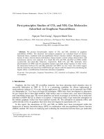
Fig. 3. Channel gains from the ANSI model and from measured data for 25
500-m users sampled at every 100 frequency tone.
Three types of illustrative examples are provided in this
section. The first involves measured data and focuses on
the case where all lines are 500 m and all use the ZF
diagonalizing precoder bit-rate (5) to calculate the downstream
performance and the ZF precoder bit-rate (11) for upstream
performance. While the lengths of lines within a DSL network
can vary, FTTN networks typically consist of lines up to 500
m. Hence, the 500-m measured data case provides a realistic
assessment of a typical FTTN network. The second illustrative
example makes use of channel models in order to evaluate
the performance of scenarios involving equal length users,
at varied line lengths. Finally, the third illustrative example
focuses on the most common case of unequal line lengths,
using channel models.
The measured data was taken by Morawski, Ho-Van, and
Zhao, in the Broadband Communications Research Laboratory
at McGill University. The setup consisted of 25 500-m long
26-AWG twisted copper pairs bundled together. The channel
gains (i.e., direct and crosstalk) and the background noise were
measured for each line.
The comparison between the ANSI model and the measured
data can be observed in Fig. 3 for the direct and crosstalk
channel gains. Fig. 4 shows the measured background noise
for both upstream and downstream transmission directions.
A. 500-m Performance Using Measured Data
For the 25-user 500-m measured data, the achievable rate
is calculated using a flat transmit PSD scheme for both nonvectored and vectored transmission. A total transmit power
of 11.5 dBm per user is used for upstream and downstream
transmission. For vectored transmission, the ZF method is
used with an effective flat PSD. Fig. 5 shows the achievable
rate in the upstream direction for each of the 25 users.
Similarly, Fig. 6 shows the achievable rate for each user in
the downstream direction. In both transmission directions, the
Vectored DSL gain is clear and shows that vectoring increases
the data-rate for each user by around 50%.
This article has been accepted for inclusion in a future issue of this journal. Content is final as presented, with the exception of pagination.
LEUNG et al.: VECTORED DSL: POTENTIAL, IMPLEMENTATION ISSUES AND CHALLENGES
120
−120
−140 dBm background noise
Noise profile upstream
Noise profile downstream
100
80
−130
Rate (Mbps)
Noise PSD (dBm/Hz)
−125
−135
60
−140
40
−145
20
−150
9
0
2
4
6
8
10
Frequency (MHz)
12
14
16
0
18
Flat PSD Vectored
Flat PSD Non−Vectored
0
5
10
15
20
25
User #
Fig. 4. Background noise PSD of -140 dBm/Hz compared to the measured
background noise PSD in the 25 500-m users setup sampled at every 100
frequency tone.
Fig. 6. Achievable downstream rate for each user using the 25 500-m user
measured data.
35
100
30
Flat PSD Vectored
Flat PSD Non−Vectored
90
80
25
15
Flat PSD Vectored
Flat PSD Non−Vectored
10
Rate (Mbps)
Rate (Mbps)
70
20
60
50
40
30
20
5
10
0
0
5
10
15
20
25
User #
0
0
500
1000
1500
Distance (m)
Fig. 5. Achievable upstream rate for each user using the 25 500-m user
measured data.
Fig. 7. Achievable upstream rate per user in a 25-user setup over different
lengths.
B. Performance Using Channel Model
While using measured data provides realistic assessments
of the performance, it is far more difficult to obtain measured
data for generalized scenarios (i.e., varied line lengths). As
such, in order to investigate the performance of scenarios for
various line lengths, ANSI channel models are used.
When using the ANSI channel models, the channels become
symmetrical and identical for all users with identical line
lengths. Thus, the resulting data-rates will be identical for
each user if the same parameters are used. Hence, instead
of showing the data-rate for each user at a given distance, we
show the achievable data-rate per user at various line lengths.
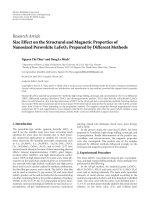
Fig. 7 shows the achievable rate in the upstream direction
for various lengths of a bundle of 25-users. Similarly, Fig. 8
shows the achievable rate in the downstream direction. The
vectored gain is quite remarkable when the length is within
500 m. This coincides with the measured data performance
gains discovered in Section IV-A. At long distances, the direct
and crosstalk channel gains are so low that removing crosstalk
does not have any substantial benefit. This can be particularly
observed in the upstream transmission at lengths above 1000
m. This further reinforces the benefits of DSL with respect
to length and further justifies the adoption of the FTTx type
network topologies.
Comparing the results from the measured case to the
channel model, we see that the measured non-vectored rates
are slightly better than predicted by the rate-reach results. This
is due to the rate-reach results using the more pessimistic
99% worst-case model. On the other hand, the vectored rates
are slightly worse than predicted by the rate-reach model.
This is because as crosstalk is cancelled, the background
noise becomes main interferer, and because the measured
background noise is greater than that used by the empirical
model in the better low-frequency downstream and much
greater in the upstream bands, as shown in Fig. 4.
This article has been accepted for inclusion in a future issue of this journal. Content is final as presented, with the exception of pagination.
10
IEEE COMMUNICATIONS SURVEYS & TUTORIALS, ACCEPTED FOR PUBLICATION
60
250
Flat PSD Vectored
Flat PSD Non−Vectored
Flat PSD Vectored
Flat PSD Non−Vectored
50
200
Rate (Mbps)
Rate (Mbps)
40
150
100
30
20
50
0
10
0
500
1000
0
1500
0
5
10
Fig. 8. Achievable downstream rate per user in a 25-user setup over different
lengths.
V. V ECTORED DSL I MPLEMENTATION
This section discusses practical implementation issues regarding Vectored DSL and discusses some potential solutions.
A. Vectoring Types
A DSLAM services up to 192 or 384 or more customers
depending on the size of the shelf [1]. Within each DSLAM
are line-cards, each consisting of 24, 48 or more lines (or
pairs) [1]. Vectored DSL can be performed in one of two
vectoring modes: DSLAM level or line-card level vectoring
[1] (also referred to as NodeScale or LineCard vectoring by
[20]). DSLAM level vectoring performs joint vectoring across
all line-cards in a particular DSLAM, while line-card vectoring
applies vectoring separately for each line-card and treats the
crosstalk generated by other line-cards as noise. Intra-line-card
20
25
Fig. 9.
Achievable upstream rate for each user in the 25-user near-far
scenario. The line length for each user increases from user #1 towards user
#25.
120
C. Near-Far Case
Flat PSD Vectored
Flat PSD Non−Vectored
100
80
Rate (Mbps)
The previous two Vectored DSL performance assessments
only give an insight on its gains when every user has the
same line lengths. However, scenarios like binder C in Fig. 1
are very common, where a near-far effect can be observed.
Fig. 9 and Fig. 10 show the gain of vectoring over one
implementation of binder C for upstream and downstream
transmissions, respectively. In this implementation, there are
25 users with uniformly distributed lengths between 500 and
1000 m. One can observe that the most important gain is on the
far users (with longer line lengths) in the upstream direction.
This is because the far users no longer receive large crosstalk
from the near users; without vectoring, the far users would
receive large amount of crosstalk from the near users.
It is interesting to note that the performance gain increase
per-line is dependent on each user’s own line length, regardless
of whether or not all lines are of equal length. This is due to the
fact that once the crosstalk has been removed, it is as though
each line is operating independently. Hence, a performance
increase of at least 50% should be expected for non-equal
line lengths as well, depending on the amount of crosstalk
present in the system prior to vectoring.
15
User #
Distance (m)
60
40
20
0
0
5
10
15
20
25
User #
Fig. 10. Achievable downstream rate for each user in the 25-user near-far
scenario. The line length for each user increases from user #1 towards user
#25.
crosstalk (i.e., within the same line-card) is typically 8-10 dB
larger than the inter-line-cards crosstalk; however, the interline-card crosstalk still provides significant coupling.
DSLAM level vectoring mode has the potential to partially
or fully cancel the crosstalk in the entire DSLAM, leading
to significant rate improvements at a high computational
cost. Line-card level vectoring provides a small rate increase;
however, its computational complexity is significantly reduced
as compared to that of DSLAM level vectoring.
An alternative to full DSLAM level vectoring or line-card
level vectoring is to applying vectoring across the dominant
sources of crosstalk. Typically, there are only a handful of
dominant crosstalk sources limiting the system performance.
If the dominant crosstalk signals are suppressed using vectoring, then the only weaker crosstalk signals would remain.
Clearly, optimal performance is achieved by cancelling all the
crosstalk signals [21]; however, often simply suppressing the
the strongest crosstalk signals is sufficient to achieve close
to optimal performance for both DSLAM level vectoring
This article has been accepted for inclusion in a future issue of this journal. Content is final as presented, with the exception of pagination.
LEUNG et al.: VECTORED DSL: POTENTIAL, IMPLEMENTATION ISSUES AND CHALLENGES
10
h1,1
k
2,1
k
3,1
hk
4,1
h
k
h5,1
k
h6,1
k
0
h
−10
−20
dB
−30
−40
−50
−60
−70
−80
−90
0
Fig. 11.
500
1000
1500
2000 2500
Tone index
3000
3500
4000
4500
Channel gains for 6-pair 600-ft 24-AWG cable bundle [22]
and line-card level vectoring. This approach is referred to
as partial crosstalk cancellation and will be discussed in
greater detail in Section VI. An important factor for partial
crosstalk cancellation is the feasibility of implementation.
In particular, it is crucial to intelligently determine which
crosstalk signals should be cancelled fast enough to allow for
it to be implemented while limiting the performance losses
due to the presence of crosstalk.
B. Computational Resources
Vectored DSL provides significant data-rate improvements,
at the expense of computational resources. Two significant
computational issues are memory constraints and computational complexity.
1) Memory Constraints: The channel gain matrices, Hk ,
must be estimated/measured and stored for vectoring. Assuming that each channel gain, hn,m
, is represented by B
k
bytes, then the memory required to save all Hk matrices is
N 2 KB (bytes). Consequently, the DSLAM level vectoring
requires C 2 times memory size more than the line-card level
vectoring where C is the number of line-cards per DSLAM.
For example, consider a VDSL2 system with a DSLAM
consisting of 192 users, 4 line-cards (each servicing 48
users), 4096 frequency tones and assuming that each channel
gain is represented by 4 bytes. The memory size will be
(4 × 48)2 × 4096 × 4 ≈ 604 (MBytes) for DSLAM level
vectoring and 482 × 4096 × 4 ≈ 38 (MBytes) for each
individual line-card level vectoring, respectively.
With a symbol rate of fs , the memory bandwidth required
is N 2 KBfs (bytes/s). Following with the previous example,
with fs = 4000 (symbols/s), the memory bandwidth required
would be 2.4 (TBytes/s) for DSLAM level vectoring and
148 (GBytes/s) for each line-card level vectoring, respectfully.
These memory bandwidth requirements are very significant
and would likely factor into the feasibility of the vectoring
approach taken. Various interpolation and partial cancellation
techniques can be applied to overcome the memory requirements [23] [24] [25]. The interpolation techniques are based
11
on the fact that the channel gains, hn,m
, vary relatively
k
slow with respect to frequency (see Fig. 11). As a result,
only storing the channel gain matrices corresponding to the
frequency tones k = (v − 1)Kg + 1 for v = 1, 2, ..., K/Kg
can reduce the memory size and the memory bandwidth by
a factor of (Kg − 1). The intermediate channel gain matrices
can be interpolated. The results of [24] illustrated that the
interpolation technique can reduce the memory (or memory
bandwidth) storage by 99.2%, while only experiencing a 4.4%
decrease in the data-rate relative to the no interpolation case. It
is worthwhile to note that even though the data-rate is reduced
due to the interpolation technique, there was still a 25.2% net
improvement in the data-rate relative to the no vectoring case.
The partial cancellation technique (discussed in more detail
in Section VI) adaptively employs vectoring on selected lines
and frequencies. By carefully and appropriately selecting
the lines and frequencies used for vectoring, a significant
reduction in the memory size (or memory bandwidth) can be
achieved with a negligible performance degradation.
2) Computational Complexity: Vectored DSL provides significant performance improvements but also requires significant computational power. For example, the ZF precoder/canceller requires computing the inverse of the channel
matrix for all frequency tones. The computational complexity
of computing the inverse of the channel matrix with many
lines (e.g., a 192 × 192 matrix) for each frequency tone (e.g.,
4096 tones) is very large. Even though using the RWDD of
the channel matrices to approximate the inverse of the channel
matrix can dramatically reduce the number of computations
required [26], the computational resources may not be sufficient to apply vectoring across all lines. In order to reduce
the size of the channel gain matrix and the number of tones
involved in vectoring, various techniques for interpolation,
partial cancellation, and priority settings (i.e., apply vectoring
on lines with high priority) can be utilized.
C. Training Process
During the training process, channel gains are required for
computing the coefficients of the pre-coder/canceller. This can
be done through channel estimation which can be implemented
at the receiver which then feeds back the estimated channel
gains to the transmitter (if necessary) via bandwidth-limited
channels [25]. With any practical system, channel estimation
provides imperfect channel knowledge. The effect of imperfect channel knowledge on Vectored DSL is investigated in
Section VII. While it is important to get somewhat accurate
channel knowledge, there is an inherent trade-off between the
computational time to acquire accurate channel knowledge. In
particular, it may be beneficial to apply a scheme that provides
less accurate channel knowledge but requires significantly less
computational time, while trying to minimize the performance
loss.
As an example to demonstrate some issues and solutions
with respect to the training process, the following considers the
training process for a pre-coder. In the G.993.5 standard [27],
pre-coder training is achieved by the VDSL2 Transceiver Unit
at the Operator side (VTU-O) transmitting a pilot sequence
during its sync symbol, once every 257 DMT symbols. The
This article has been accepted for inclusion in a future issue of this journal. Content is final as presented, with the exception of pagination.
12
IEEE COMMUNICATIONS SURVEYS & TUTORIALS, ACCEPTED FOR PUBLICATION
coefficients of the pre-coder are estimated and updated using
a Least-Mean Squared (LMS) algorithm, based on errors
between the pilot symbols and the signals at the output of
the frequency-domain equalizer calculated by the VDSL2
Transceiver Unit at the Remote side (VTU-R) and fed back
to the VTU-O.
Due to limited feedback channel bandwidth and the large
number of frequency tones used in xDSL systems, each error
on each frequency tone is quantized by a low number of bits
(e.g., only 0.7 bits per error sample dimension [25]), leading
to high quantization error and resulting in a low data-rate at
convergence due the estimation errors. Again, the interpolation
technique is an efficient solution in which only the error on
every k th tone is fed back. Hence, the number of quantization
bits increases as there are fewer error values to feedback,
leading to an improved estimation of the channel and data-rate.
For example, with an interpolation factor of 8, the number of
quantization bits is increased to 5 bits per error dimension
with only a minor performance degradation [25].
Since the pilots are only transmitted every 257 DMT
symbol, the convergence of training algorithms can be very
slow (e.g., 10 seconds, exceeding an acceptable period of
time). It is shown in [25], that at least 12 quantization bits per
error sample dimension are required for converging to a high
data-rate within 10 seconds while the limit is 5 bits per error
dimension when using the interpolation technique with a factor
of 8. In order to solve the problem of high quantization error
and slow training convergence, scaling the error sample before
quantization is essential [28]. The error scaling takes advantage of the fact that the error magnitude decays rapidly as the
algorithm converges. That means the quantization range can be
considerably reduced as the algorithm converges, ensuring a
lower quantization error even when very few feedback bits are
used. Simulation results illustrated that with 5 quantization bits
per error sample dimension and the error scaling, the algorithm
can converge within 10 seconds with minor data-rate reduction
resulting from channel estimation errors.
D. System Parameter Adjustments
Before vectoring is applied, crosstalk is the dominant impairment degrading the system performance. With perfect vectoring, all FEXT signals are eliminated and thus, the variable
noise sources such as impulse noise or Radio Frequency Interference (RFI) can become dominant and cause transmission
errors and re-initialization [29] because the interference will
have greater relative variations (where the absolute variation
remains and the interference reduces with 0 FEXT). Hence,
system parameters used for impulse noise protection must be
correspondingly adjusted to cope with the remaining noises
after vectoring.
There are many configuration tools available to mitigate the
impact of these noise sources [1]. Seamless Rate Adaption
(SRA) can be used in a slow-changing noise environment to
provide more stability while interference sources fluctuate by
preventing a line from retraining. Combinations of Impulsive
Noise Protection (INP), Inter-leaver Delay and physical layer
retransmission can be used to mitigate the effects of impulsive
noise. Save Out Showtime (SOS) can be used to prevent
lines from retraining when crosstalk increases suddenly (e.g.,
impulsive noise). Other tools such as virtual noise and erasure
decoding can provide additional line stability. As vectoring is
introduced, the parameters used in the configuration tools will
become more important in order to provide a tradeoff between
stability and vectoring performance.
E. Managing Non-Vectored Lines and Legacy CPEs
Occasionally, DSL binders may contain mixes of lines
belonging to different xDSL technologies (e.g., VDSL and
ADSL lines). Similarly, DSL binders may contain both vectored and non-vectored lines. The crosstalk generated from
non-vectored lines onto the vectored lines cannot be cancelled
and may cause significant performance degradation to the
vectored lines [1], [30]. One method to solve this problem
would involve the combination of DSM levels 1, 2 and 3 to
cancel out crosstalk where possible and mitigate it using DSM
levels 1 or 2 where it is not possible. Another approach would
involve upgrading the respective CPEs to vectoring-capable
CPEs.
The legacy CPE issue arises in areas where outdated
services are being provided (e.g., ADSL, VDSL, VDSL2)
but it is desired to also deploy Vectored DSL to provide
higher data-rates [1]. The Vectored DSL system should be
capable of providing the increased data-rates associated with
Vectored DSL, while still providing the existing services to
legacy customers without upgrading their CPEs. In order to
solve this problem, the ITU has developed a downloadable
firmware known as “vectoring-friendly CPE” which can allow
for existing CPEs to operate in a “vectoring-friendly” mode
[1]. This would allow legacy lines to operate as before, while
allowing for the crosstalk generated by those lines to the
vectoring lines to be cancelled.
F. Managing Unbundled Lines
Unbundled lines arise when competing service providers
each have lines within the same binder (e.g., two Vectored
DSLAMs from different service providers share a binder)
[1], [31]. The interference between clusters cannot be cancelled due to a lack of coordination between competing
service providers. Ideally, cooperation would allow for all the
crosstalk to be cancelled (e.g., using a third-party coordination
engine). When coordination is not possible, the combination
of DSM levels 1, 2 and 3 can again be employed to mitigate
any remaining crosstalk which could not be vectored.
Another issue is that of the physical location of lines within
a binder. The crosstalk between lines in close proximity is
significantly larger than the crosstalk between lines that are
far apart; hence, it would be ideal to place lines which will
be jointly-vectored close to one another. Unfortunately, the
rewiring of lines within a binder is difficult, costly and not
practical from an implementational perspective [1].
VI. PARTIAL C ANCELLATION
Vectored transmission is an intensive process with a computational complexity that grows linearly with the number of
frequency tones and quadratically with the number of users.
This article has been accepted for inclusion in a future issue of this journal. Content is final as presented, with the exception of pagination.
For example, say 50 users and 2000 frequency tones, precoding requires at least 5 million multiplications per symbol.
With a symbol rate of 4000 Hz, at least 20 billion multiplication and 20 billion addition operations are required every
second. Partial cancellation reduces the computational load by
only removing the crosstalk between specific users on specific
frequency tones.
The partial cancellation method uses the ZF method for both
upstream and downstream transmissions. It works by setting
some values in the pre-coding matrix or the cancellation
matrix to zero. By doing so, the number of operations required
for crosstalk cancellation can be approximately proportionally
reduced with the number of elements set to zero. Therefore,
for upstream transmission, we want a cancellation matrix Pk
such that:
[Pk Hk ](n,m) =
=1
0 if cn,m
k
n,m
1 if ck = 1
=1
0 if cn,m
k
n,m
1 if ck = 0
,
with Hk Pk representing the effective channel.
A simple partial cancellation interpretation was developed
in [32] for upstream transmission and in [33] for downstream
transmission. In upstream transmission and in combination
with the CWDD nature of upstream transmission in the DSL
networks, it was determined that by letting:
[Pk ](n,m) =
n,m
=1
[H−1
k ](n,m) if ck
n,m
0
if ck = 0
,
the SNR would be approximately:
SNRnk ≈
σkn +
13
100
90
Full vectoring
Partial cancellation
No vectoring
80
70
0
20
40
60
80
Percent of total crosstalk tap allocated
100
Fig. 12. Partial crosstalk cancellation sum rate with a varying number of
cancellation taps.
where cn,m
represents the cancellation tap on the crosstalk
k
generated from user m to n on frequency tone k. Since Pk Hk
is the effective channel after cancellation, the cancellation taps
cn,m
effectively removes the crosstalk generated from user
k
m to user n on frequency tone k. Similarly, for downstream
transmission, we want a pre-coding matrix Pk such that:
[Hk Pk ](n,m) =
Percent of full vectoring sum rate
LEUNG et al.: VECTORED DSL: POTENTIAL, IMPLEMENTATION ISSUES AND CHALLENGES
2 n
|hn,n
k | sk
n,m 2 m .
| sk
m:cn,m =0 |hk
k
Therefore, it was concluded that partial crosstalk cancellation
using zero-forcing does not change the statistics of the noise
nor does it amplify the non-cancelled crosstalk.
In [32], a joint tone-line selection algorithm was proposed
where the cancellation taps cn,m
are assigned based on the
k
greatest lost from no crosstalk to having a single crosstalk
generator from sm
k . By using the joint tone-line selection
on a 4×300-m and 4×1200-m user near-far scenario, Partial
Crosstalk Cancellation (PCC) obtained 90% of the performance of full cancellation with only 29% of the cancellation
taps active, and 80% of the full performance in downstream
transmission with only 20% of the taps active. The precoder
for partial cancellation can also be obtained iteratively by
using error signal feedback. An analysis on the performance
and convergence of the adaptive partial cancellation precoder
is developed in [34].
The results from applying an optimal PCC in the downstream direction to the 25-user 500-m measured case from
Section IV using a flat PSD are shown in Fig. 12. The sumrate over all 25 users shows that it is possible to achieve
90% of the full vectoring performance with only 40% of
the cancellation taps. Thus, with only 40% of the number
of computations required by full vectoring, PCC can already
increase the performance by 50% over the non-vectoring case.
The performance of PCC is also demonstrated in [35] where it
is shown though simulations that cancelling around 50% of the
crosstalk can achieve significant gain in a branched topology
system with both vectored and non-vectored capable users.
A. Partial Cancellation and Spectrum Management
The combination of PCC and spectrum management was
investigated in [36], [37]. With spectrum management, the
effect of crosstalk between users is reduced by allocating
power to frequency tones generating less crosstalk. Whereas,
for PCC, frequency tones with large crosstalk values are
targeted to remove the specific crosstalk. Hence, if PCC and
spectrum management were to run independently, the mutual
benefit would not be exploited. In the independent case, it is
likely that the cancellation taps will be assigned to crosstalk
links with high crosstalk channel gain as with the joint toneline selection algorithm. However, it is also likely that a
spectrum management algorithm would allocate little to no
power to the interfering users on those crosstalk links. This
combination would result in an inefficient use of power since
it would result in loading little power on tones where the
crosstalk has been cancelled. Therefore, there is a need of a
joint-optimization for spectrum management and cancellation
tap allocation.
By applying a binary-version of Optimal Spectrum Balancing (OSB) on the non-cancelled crosstalk, [37] showed that in
a 2×600 m and 2×1200 m near-far topology, it is possible to
achieve the same performance as full crosstalk cancellation by
only using 30% of the crosstalk cancellation taps. Moreover,
with only 25% of the cancellation taps active, the performance
remains nearly crosstalk free.
This article has been accepted for inclusion in a future issue of this journal. Content is final as presented, with the exception of pagination.
14
IEEE COMMUNICATIONS SURVEYS & TUTORIALS, ACCEPTED FOR PUBLICATION
B. Cross-layer Partial Cancellation
A cross-layer approach where delay, rate, and cancellation
taps were considered in [38] by using the following combined
optimization problem
n
Q (t)R
max
cn,m
∀k,n,m=n
k
n
(12)
n∈N
ˆ k = Hk +
The estimated channel matrix can be written as H
ˆ
ΔHk . The inverse of Hk can be written as [46]:
ˆ −1 = (Hk + ΔHk )−1
H
k
−1
I + ΔHk H−1
= H−1
k − Hk
k
= I − (EUS )k xk +
where C total represents the maximum number of cancellation
taps and Qn (t) is the queue at user n and at time t. Whereas
Problem (12) is akin to the rate adaptive problem in [3], a
cancellation tap reduction version of the problem was also
investigated in [38] by modifying the objective function from
Problem (12) to
Qn (t)Rn − V C(t),
ΔHk xk
ˆ −1 zk ,
H
k
where (EUS )k is an N × N matrix representing the error in
estimation associated with upstream transmission on frequency
tone k. Therefore, the upstream bit-rate for line n on frequency
tone k can be expressed as:
bnk = log2
1
SNRnk ,
Γ
1+
where
n∈N
where V is some cost factor and C(t) is the number of
cancellation taps assigned at time t.
VII. E FFECT OF C HANNEL E STIMATION E RROR ON
V ECTORED DSL
This paper has demonstrated the potential performance
benefits associated with Vectored DSL; however, Vectored
DSL requires knowledge of the channel in order to properly
function. In practice, channel knowledge is subject to inaccuracies. As such, this section investigates the effect of channel
estimation error on the performance of practical Vectored DSL
systems.
DSL channel estimation is a well-researched subject. In
[39], crosstalk was estimated using a least-squares method
by making use of an impartial third-party. A maximumlikelihood channel estimation technique using a training-aided
expectation-maximization algorithm was proposed in [40]
and [41]. A crosstalk channel estimation technique based on
SNR measurements at the receiver was presented in [42].
An optimal FEXT channel estimation technique in the leastsquares sense was proposed in [43]. As well, a maximum
likelihood channel estimator was derived in [43] and the
effect of channel estimation error on the performance of nonvectored DSM systems was discussed in [44]. Furthermore, the
effect of generalized regression neural network-based channel
estimation on Vectored DSL was investigated in [45].
In this section, a ZF canceller is applied to upstream transmission and a DP is applied to the downstream transmission.
A. Upstream Zero Forcing
SNRnk
1 − (EUS )k
=
2
m=n
(EUS )k
(n,m)
2
(n,n)
sm
k
snk
ˆ −1
H
k
+
2
(n, )
k
(13)
σkn
.
It can be seen that as ΔHk approaches the all-zeros matrix,
(EUS )k vanishes and bnk approaches that of ideal channel
knowledge:
bnk (Ideal) = log2
1+
snk
1
Γ
H−1
k
2
(n, )
.
σkn
B. Downstream Diagonalizing Pre-coder
Downstream vectored transmission with an estimated channel matrix is given by (15).
ˆ 1,1 , . . . , h
ˆ N,N }xk + zk .
ˆ −1 diag{h
y
ˆk = Hk βk−1 H
k
k
k
(15)
Similar to Section VII-A, substituting (14) into (15) gives:
ˆ 1,1 , . . . , h
ˆ N,N }xk −
y
ˆk = zk + βk−1 diag{h
k
k
βk−1 I + ΔHk H−1
k
−1
ˆ 1,1
ˆ N,N } xk
ΔHk H−1
k diag{hk , . . . , hk
(EDS )k
=
ˆ 1,1 , . . . , h
ˆ N,N }
βk−1 diag{h
k
k
− (EDS )k xk + zk ,
where (EDS )k is an N × N matrix representing the error
in estimation associated with downstream transmission on
frequency tone k. Therefore, the downstream bit-rate for line
n on frequency tone k can be expressed as:
bnk
= log2
1
1+
Γ
βk−1 ˆhn,n
− (EDS )k
k
m=n
(EDS )k
(n,m)
2
(n,n)
2
(˜
s)m
k
(˜
s)nk
+
2
Upstream vectored transmission with an estimated channel
matrix is given by (13).
k
−1
(EU S )k
n∈N m∈N k∈K
ˆ −1 yk = H
ˆ −1 (Hk xk + zk )
ˆk = H
x
k
k
ˆ −1 zk .
ˆ −1 Hk xk + H
=H
(14)
Substituting (14) into (13) gives:
cn,m
≤ C total ,
k
max
ΔHk H−1
k .
ˆ −1 zk − H−1 I + ΔHk H−1
ˆ k = xk + H
x
k
k
k
such that
cn,m
∀k,n,m=n
k
−1
σkn
,
where (˜
s)nk = E Qk (n, ) xk /Δf . Similar to the upstream case, as ΔHk approaches the all-zeros matrix, (EDS )k
vanishes and bnk approaches that of ideal channel knowledge:
bnk (Ideal) = log2
1+
2
s)nk
1 βk−2 |hn,n
k | (˜
.
Γ
σkn
This article has been accepted for inclusion in a future issue of this journal. Content is final as presented, with the exception of pagination.
LEUNG et al.: VECTORED DSL: POTENTIAL, IMPLEMENTATION ISSUES AND CHALLENGES
15
TABLE I
E FFECT OF E STIMATION E RROR ON V ECTORED DSL FOR VARIED Δ.
Δ
0
1
2
3
4
5
Upstream
Sum Rate
% of
(Mbps)
Δ=0
783
100.0
756
96.6
723
92.3
691
88.2
660
84.3
630
80.4
Avg. %
Diff
0.0
11.6
23.4
35.9
49.3
64.3
Downstream
Sum Rate
% of
Avg. %
(Mbps)
Δ=0
Diff
2596
100.0
0.0
2536
97.7
11.6
2423
93.3
23.4
2306
88.8
35.9
2194
84.5
49.4
2085
80.3
64.2
Fig. 13.
Phantom DSL conceptual drawing.
C. Simulation Results
In order to test the effects of channel estimation error on the
performance of Vectored DSL, the values of the true channel
measurements were uniformly modified by ±Δ [dB], for varying values of Δ, on the 500-m measured data test case. Note
the FEXT channel estimation error for the estimator derived
in [43] was approximately uniformly distributed within [−3, 3]
dB, corresponding to Δ = 3. As such, the value of Δ = 3 is
assumed to be typical for practical networks [44]. The value
of Δ was varied from 0 to 5, where Δ = 0 corresponds
to using the true measured values. Table I shows the sum
rate achieved, the corresponding percentage relative to perfect
knowledge, and the average percent difference for each value
of Δ. As can be seen in Table I, imperfect channel knowledge
(up to Δ = 5) results in over 80% of the perfect knowledge
sum rate. Moreover, with Δ selected according to what is
typically seen in practice (Δ = 3) [43] [44], over 88% of
the perfect knowledge sum rate was achieved. As such, for
practical deployment, it is reasonable to assume a 12% loss
in throughput due to imperfect channel knowledge.
VIII. V ECTORED DSL A PPLIED TO P HANTOM
T ECHNOLOGY
A. Phantom DSL Technology: An Overview
DSL Phantom mode technology [47] [48] is an innovative
method for increasing DSL data-rates [49]. Phantom technology transports three channels worth of data over two physical
channels. More specifically, Phantom technology makes use of
coordination between the two physical channels to achieve the
same data-rate that could be achieved using three independent
physical channels. The key concept is the use of a phantom (or
virtual) channel. Information desired to be sent over the phantom channel is split between the two physical channels and can
be recovered at the receiver after processing. While the amount
of data transmitted within a given time frame increases, the
process generates excess crosstalk. Therefore, Vectored DSL
can be applied in addition to Phantom technology to remove
the crosstalk.
Phantom mode requires more sophisticated modems that are
capable of supporting three-pair bonding. More specifically, it
requires a modem that can recover the three channels worth of
data from the data received over the two physical channels. As
well, in order to combine Vectored DSL with Phantom mode
technology, the DSL modem’s chip set must have enough
processing power to vector the two physical channels and the
phantom channel.
The concept of Phantom DSL can be generalized to more
than two physical channels; that is, if C physical channels are
used, there can be up to C − 1 phantom channels. Hence, for
every C physical channels, 2C − 1 channels worth of data can
be transmitted. Increasing the number of physical channels
and phantom channels can significantly increase data-rates,
at the expense of more complicated processing and hardware
requirements. In practice, it is common for a household to
have two twisted-pair copper wire loops at their home (i.e.,
C = 2). In many cases, increasing the number of physical
channels would require the re-wiring of lines in a binder which
is often not practical.
A conceptual drawing of Phantom mode technology is
shown in Fig. 13 for the C = 2 case. As shown in Fig. 13,
the Phantom signal (denoted by ±c) is divided between the
two physical channels. At the receiver, the desired signals a, b
and c can be recovered.
More technically, Phantom mode makes use of both differential signals and common mode signals [50]. Differential
signals are sent over the two physical twisted-pair channels,
while a third signal which is in common mode with each of
the physical twisted-pairs, but in differential mode between
them is also sent. Applying a differential amplifier to each of
the physical channels filters out the common-mode signal so
that the differential signals can be recovered [4]. Similarly,
amplifying the signal between the two pairs recovers the
common-mode (phantom) signal [4]. This can be seen in
Fig. 13, since the difference between the top twisted-pair is
c + a − (c − a) = 2a and the difference between the bottom
twisted-pair is −c+b−(−c−b) = 2b. Similarly, the difference
between the “virtual plus” (red) from the top twisted-pair and
the “virtual minus” (blue) from the bottom twisted-pair gives
c+a−(−c−b) = 2c+a+b, where a and b are known. Hence,
the signals a, b, and c can all be recovered at the receiver.
B. Testing Results
Phantom mode technology combined with Vectored DSL
is seen as the future for wire-line communications. As such,
several companies have tested the performance of Phantom
DSL in a lab-setting, including Alcatel-Lucent, Nokia Siemens
Networks and Huawei.
Table II summarizes the downstream data-rates reported
by the three companies using phantom mode and vectoring
for various number of pairs and line lengths within a lab-
This article has been accepted for inclusion in a future issue of this journal. Content is final as presented, with the exception of pagination.
16
IEEE COMMUNICATIONS SURVEYS & TUTORIALS, ACCEPTED FOR PUBLICATION
TABLE II
S UMMARY OF DOWNSTREAM P HANTOM AND V ECTORED DSL
DATA - RATES BY COMPANY IN A LAB - SETTING
Alcatel-Lucent
Nokia Siemens
Networks
Huawei
Number of
Pairs
Two
Two
Four
Four
Four
Four
Downstream
Speeds (Mbps)
100
390
910
825
750
700
Line
Lengths (m)
1000
400
400
400
500
400
setting1,2,3 . Alcatel-Lucent showed that by combining Phantom mode with Vectored DSL, it could achieve downstream
speeds of 390 Mbps over 400 m using two pairs or 910 Mbps
over 400 m using four pairs. Alcatel-Lucent also showed that it
could achieve downstream speeds of 100 Mbps at 1 km using
two pairs. Similarly, Nokia Siemens Networks showed that
when combining Phantom mode and Vectored DSL, it could
achieve 825 Mbps over 400 m using four pairs and that it
could achieve 750 Mbps over 500 m using four pairs. Huawei
showed that by combining Phantom mode and Vectored DSL,
they could achieve 700 Mbps at 400 m using four pairs.
The application of Phantom mode technology for DSL was
also investigated in [4]. It was shown in [4] using VDSL2
alone, an 800 m line could support 50 Mbps downstream,
while using Phantom mode, a 1300 m line could support 50
Mbps downstream (an improvement of 62.5%).
IX. C ONCLUDING R EMARKS
This paper presented an overview of Vectored DSL. The
main vectoring techniques for upstream and downstream transmission were presented. It was shown that ZF is suitable for
DSL given the CWDD and RWDD of the DSL channel. Simulation results were provided to show the performance gains
in terms of data-rates using Vectored DSL. Many practical
implementation issues regarding Vectored DSL were discussed
and some potential solutions were provided. The topic of
partial crosstalk cancellation for reducing the computational
complexity was also discussed. Then, the effects of channel
estimation error on the performance of Vectored DSL was investigated. Finally, Phantom DSL was discussed as a potential
future path for Vectored DSL.
Acknowledgements
The authors would like to thank the reviewers for their
helpful comments.
R EFERENCES
[1] R. Zidane, S. Huberman, C. Leung, and T. Le-Ngoc, “Vectored DSL:
Benefits and Challenges for Service Providers,” IEEE Commun. Mag.,
Feb. 2013.
1 M. Rickn¨
as, “Vendors Closing in on 1 GBps Using DSL”, IDG News,
Oct. 2010, closing in on
1g bps using dsl.html
2 S. Vanhastel, “The investment required to upgrade DSL is quite
small”, Alcatel-Lucent, Apr. 2010, />27/dsl-will-phantom-channels-become-real-deployments.html
3 D. O’Shea, “BWF: Vendors’ DSL ambitions moving full speed ahead”,
Penton Media Inc., Oct. 2010, />services/news/BWF-Vendors-DSL-ambitions-moving-full-speed-ahead-1029
[2] J. Cioffi, M. Brady, V. Pourahmad, S. Jagannathan, W. Lee, Y. Kim,
C. Chen, K. Seong, D. Yu, M. Ouzzif, H. Mariotte, R. Tarafi, G. Ginis,
B. Lee, T. Chung, and P. Silverman, “Vectored DSLs with DSM: The
road to Ubiquitous Gigabit DSLs,” in Proc. World Telecommun. Conf.,
May 2006.
[3] S. Huberman, C. Leung, and T. Le-Ngoc, “Dynamic Spectrum Management (DSM) Algorithms for Multi-User xDSL,” IEEE Commun. Surveys
Tuts., vol. 14, no. 1, pp. 109–130, Feb. 2012.
[4] E. Oswald, “Application of a Phantom Circuit for xDSL Communications,” in Proc. 13th International OFDM-Workshop, Aug. 2008.
[5] J. M. Cioffi and M. Mohseni, “Dynamic Spectrum Management A
Methodology for Providing Significantly Higher Broadband Capacity to
The User,” Telektronikk, pp. 126–137, Apr. 2004.
[6] Thomas Starr and Massimo Sorbara and John M. Cioffi and Peter J.
Silverman, DSL Advances. Prentice-Hall, 2003.
[7] T. Starr, J. Cioffi, and P. Silverman, Understanding Digital Subscriber
Line Technology. Upper Saddle River, NJ: Prentice-Hall, 1999.
[8] A. Shaybani and J. Kamali, “Carriers have two routes to ADSL testing,” EE Times, Oct. 2003, />4139618/Carriers-have-two-routes-to-ADSL-testing.
[9] A. Paulraj, D. Gore, R. Nabar, and H. Bolcskei, “An overview of MIMO
communications - a key to gigabit wireless,” Proc.IEEE, vol. 92, no. 2,
pp. 198–218, Feb. 2004.
[10] R. Cendrillon, G. Ginis, E. Van den Bogaert, and M. Moonen, “A NearOptimal Linear Crosstalk Canceler for Upstream VDSL,” IEEE Trans.
Signal Process., vol. 54, no. 8, pp. 3136–3146, Aug. 2006.
[11] G. Ginis and J. Cioffi, “Vectored Transmission for Digital Subscriber
Line Systems,” IEEE J. Sel. Areas Commun., vol. 20, no. 5, pp. 1085–
1104, Jun. 2002.
[12] R. Cendrillon, G. Ginis, E. Van den Bogaert, and M. Moonen, “A
Near-Optimal Linear Crosstalk Precoder for Downstream VDSL,” IEEE
Trans. Commun., vol. 55, no. 5, pp. 860–863, May 2007.
[13] M. Tomlinson, “New automatic equaliser employing modulo arithmetic,”
Electron. Lett., vol. 7, no. 5-6, pp. 138–139, 1971.
[14] H. Harashima and H. Miyakawa, “Matched-transmission technique for
channels with intersymbol interference,” IEEE Trans. Commun., vol. 20,
no. 4, pp. 774–780, Aug. 1972.
[15] C.-Y. Chen, K. Seong, R. Zhang, and J. M. Cioffi, “Optimized Resource
Allocation for Upstream Vectored DSL Systems with Zero-Forcing
Generalized Decision Feedback Equalizer,” IEEE J. Sel. Topics Signal
Process., vol. 1, no. 4, pp. 686–699, Dec. 2007.
[16] P. Golden, H. Dediue, and K. S. Jacobsen, Eds., Implementation and
Applications of DSL Technology. Auerbach Publications, 2008.
[17] G. Taubock and W. Henkel, “MIMO Systems in the Subcriber-Line
Network,” in Proc. 5th International OFDM Workshop, Sep. 2000.
[18] I. Bergel and A. Leshem, “The performance of zero forcing DSL
systems,” IEEE Trans. Signal Process., vol. PP, 2012.
[19] S. Zafaruddin, S. Prakriya, and S. Prasad, “Performance analysis of
zero forcing crosstalk canceler in vectored VDSL2,” IEEE Trans. Signal
Process. Letters, vol. 19, no. 4, pp. 219–222, Apr. 2012.
[20] K. Fisher, “Ikanos NodeScaleTM Vectoring for FTTN Deployments,” in
IEEE Global Telecommun. Conf. Access Forum, Dec. 2009.
[21] P. Erisksson, “VDSL2 Vectoring Performance and Deployment Aspects,” in IEEE Global Telecommun. Conf. Access Forum, Dec. 2009.
[22] D. Z. R. Morawski, K. Ho-Van and Y. Zhao, “xDSL Channel Response
and Quiet Line Noise: Measurement and Results,” McGill University,
Tech. Rep., May 2010.
[23] R. Cendrillon, “Multi-User Signal and Spectra Coordination for Digital
Subscriber Lines,” Ph.D. dissertation, Katholieke Universiteit Leuven,
Dec. 2004.
[24] A. Clausen, “VDSL2 Vectoring Architecture and System Aspects,” in
IEEE Global Telecommun. Conf. Access Forum, Dec. 2009.
[25] R. Cendrillon, F. Liming, J. Chou, G. Long, and D. Wei, “Challenges
and Solutions in Vectored DSL,” in Access Networks, ser. Lecture
Notes of the Institute for Computer Sciences, Social Informatics and
Telecommunications Engineering. Springer Berlin Heidelberg, 2010,
vol. 37, pp. 192–203.
[26] A. Leshem and L. Youming, “A Low Complexity Linear Precoding
Technique for Next Generation VDSL Downstream Transmission Over
Copper,” IEEE Trans. Signal Process., vol. 55, no. 11, pp. 5527–5534,
Nov. 2007.
[27] Self-FEXT cancellation (vectoring) for use with VDSL2 transceivers,
ITU Std. G.993.5 Std., Apr. 2010.
[28] Huawei Technologies Co.,Ltd., “Speeding up the Convergence of
Crosstalk Precoder Initialization with Error Scaling,” ITU-T SG15/Q4
contribution 09AG-047, Feb. 2009.
This article has been accepted for inclusion in a future issue of this journal. Content is final as presented, with the exception of pagination.
LEUNG et al.: VECTORED DSL: POTENTIAL, IMPLEMENTATION ISSUES AND CHALLENGES
[29] M. Mohseni, G. Ginis, and J. Cioffi, “Dynamic Spectrum Management
for Mixtures of Vectored and Non-vectored DSL Systems,” in Proc. 44th
Annual Conference on Information Sciences and Systems, Mar. 2010.
[30] G. Ginis, M. Mohseni, and J. M. Cioff, “Vectored DSL to the Rescue,”
OSP Magazine, Apr. 2010.
[31] A. Colmegna, S. Galli, and M. Goldburg, “Methods for Supporting
Vectoring when Multiple Service Providers Share the Cabinet Area,”
FASTWEB/ASSIA Vectoring White Paper, Apr. 2012.
[32] R. Cendrillon, M. Moonen, G. Ginis, K. Van Acker, T. Bostoen,
and P. Vandaele, “Partial Crosstalk Cancellation for Upstream VDSL,”
EURASIP J. Appl. Signal Process, vol. 2004, no. 10, pp. 1520–1535,
Jan. 2004.
[33] R. Cendrillon, G. Ginis, M. Moonen, and K. van Acker, “Partial
Crosstalk precompensation in downstream VDSL,” Elsevier Signal Processing, Special Issue on Signal Processing in Communications, vol. 84,
no. 11, pp. 2005–2019, Nov. 2004.
[34] I. Binyamini, I. Bergel, and A. Leshem, “Arbitrary partial FEXT
cancellation in adaptive precoding for multichannel downstream VDSL,”
IEEE Trans. Signal Process., vol. PP, 2012.
[35] M. Guenach, J. Meas, M. Timmers, O. Lamparter, J. Bischoff, and
M. Peeters, “Vectoring in DSL systems: Practices and challenges,”
in Global Telecommunications Conference (GLOBECOM 2005), Dec.
2005.
[36] J. Vangorp, P. Tsiaflakis, M. Moonen, J. Verlinden, and G. Ysebaert,
“A dual decomposition to partial crosstalk cancellation in a multiuser
DMT-xDSL environment,” EURASIP J. Advances in Signal Processing,
vol. 2007, pp. 1–11, Jun. 2007.
[37] J. Vangorp, P. Tsiaflakis, M. Moonen, and J. Verlinden, “Joint spectrum
management and constrained partial crosstalk cancellation in a multiuser xDSL environment,” Signal Processing, Special Section: Information Processing and Data Management in Wireless Sensor Networks,
vol. 87, no. 12, pp. 3131–3146, Dec. 2007.
[38] B. Li, P. Tsiaflakis, M. Moonen, J. Maes, and M. Guenach, “Dynamic
Resource Allocation Based Partial Crosstalk Cancellation in DSL Networks,” in Proc. IEEE Global Communications Conference, Dec. 2010.
[39] C. Zeng, C. Aldana, A. Salvekar, and J. Cioffi, “Crosstalk identification
in xDSL systems,” IEEE J. Sel. Areas Commun., vol. 19, no. 8, pp.
1488–1496, Aug. 2001.
[40] C. H. Aldana and J. Cioffi, “Channel Tracking for Multiple Input, Single
Output Systems using EM algorithm,” in Proc. IEEE International
Conference on Communications. IEEE Press, Jun. 2001, pp. 586–590.
[41] E. d. C. C. H. Aldana and J. M. Cioffi, “Channel estimation for multicarrier multiple input single output systems using the EM algorithm,”
IEEE Trans. Signal Process., vol. 51, no. 12, pp. 3280–3292, 2003.
[42] J. Louveaux, A. Kalakech, M. Guenach, J. Maes, M. Peeters, and L. Vandendorpe, “An SNR-Assisted Crosstalk Channel Estimation Technique,”
in Proc. IEEE International Conference on Communications, Jun. 2009,
pp. 1–5.
¨
[43] F. Lindqvist, N. Lindqvist, B. Dortschy, P. Odling,
P. O. B¨orjesson,
K. Ericson, and E. Pelaes, “Crosstalk channel estimation via standardized two-port measurements,” EURASIP J. Adv. Signal Process, vol.
2008, pp. 201:1–201:14, January 2008.
[44] N. Lindqvist, F. Lindqvist, M. Monteiro, B. Dortschy, E. Pelaes, and
A. Klautau, “Impact of crosstalk channel estimation on the DSM
performance for DSL networks,” EURASIP J. Adv. Signal Process, vol.
2010, pp. 2:1–2:11, February 2010.
[45] S. Huberman and T. Le-Ngoc, “Performance of Generalized Regression
Neural Network-Based Channel Estimation in Vectored DSL Systems,”
in Proc. IEEE Canadian Conference on Electrical and Computer
Engineering, Apr. 2012.
[46] H. V. Henderson and S. R. Searle, “On Deriving the Inverse of a Sum
of Matrices,” SIAM Review, vol. 23, no. 1, pp. 53–60, Jan. 1981.
[47] A. L. Norrell, “Multi-Line ADSL Modulation,” Patent US 6,507,608
B1, Jan. 14, 2003.
[48] J. Maes, M. Peeters, M. Gueanch, V. Le Nir, and M. Moonen, “Method
and Apparatus for DSL Communication,” Patent EP 2 091 196 A1, Aug.
19, 2009.
[49] P. Lafata, P. Jares, and J. Vodrazka, “Increasing the transmission
capacity of digital subscriber lines,” in 35th International Conference
on Telecommunications and Signal Processing, Jul. 2012, pp. 292–296.
[50] W. Foubert, C. Neux, L. Van Biesen, and Y. Rolain, “Exploiting the
phantom-mode signal in dsl applications,” IEEE Trans. Instrum. Meas.,
vol. 61, no. 4, pp. 896–902, Apr. 2012.
17
Christopher Leung received his M.Eng. and B.Eng.
in Electrical Engineering in 2011 and 2009, respectively, from McGill University, Montr´eal, Qu´ebec,
Canada. Since 2012, he joined the M.Sc. in Financial
Engineering program at HEC Montr´eal.
Mr. Leung was the recipient of the Alexander
Graham Bell Canada Graduate Scholarship from the
National Science and Engineering Research Council
(NSERC) and the Bourses de maˆıtrises en recherche
from the Fonds de recherche du Qu´ebec - Nature
et technologies (FQRNT) in 2009; and the McGill
Engineering Doctoral Award and of the Bourses de doctorat en recherche
from FQRNT in 2011.
Sean Huberman received his B.Sc. in engineering
(with first-degree honours) from Queen’s University,
Kingston, Canada, in applied mathematics and engineering control and communications, in May 2008.
He began his M.Eng. in electrical engineering at
McGill University, Montreal, Canada, in September
2008. In January 2010, he transferred into the PhD
program in electrical engineering at McGill University.
His research interests include techniques of mathematical optimization, dynamic resource allocation,
channel modeling and channel measurements.
Mr. Huberman was the recipient of the Hydro Quebec Engineering Doctoral
Award in 2009. In 2010, he was the recipient of the Vadasz Doctoral
Fellowship in Engineering. He was also the recipient of a three-year doctoral
National Science and Engineering Research Council (NSERC) award and a
three-year McGill Engineering Doctoral Award (MEDA).
Khuong Ho-Van received the B.E. (with the firstrank honor) and the M.S. degrees in Electronics and
Telecommunications Engineering from HoChiMinh
City University of Technology, Vietnam, in 2001 and
2003, respectively, and the Ph.D. degree in Electrical
Engineering from University of Ulsan, Korea in
2006. During 2007-2011, he joined McGill University, Canada as a postdoctoral fellow. Currently, he is
an assistant professor at HoChiMinh City University
of Technology. His major research interests are modulation and coding techniques, diversity technique,
digital signal processing, and cognitive radio.
Tho Le-Ngoc obtained his B.Eng. (with Distinction)
in Electrical Engineering in 1976, his M.Eng. in
1978 from McGill University, Montreal, and his
Ph.D. in Digital Communications in 1983 from
the University of Ottawa, Canada. During 19771982, he was with Spar Aerospace Limited and
involved in the development and design of satellite
communications systems. During 1982-1985, he was
an Engineering Manager of the Radio Group in the
Department of Development Engineering of SRTelecom Inc., where he developed the new point-tomultipoint DA-TDMA/TDM Subscriber Radio System SR500. During 19852000, he was a Professor at the Department of Electrical and Computer
Engineering of Concordia University. Since 2000, he has been with the
Department of Electrical and Computer Engineering of McGill University.
His research interest is in the area of broadband digital communications. He
is a senior member of the Ordre des ing´enieurs du Qu´ebec and a fellow of
the Institute of Electrical and Electronics Engineers (IEEE), the Engineering
Institute of Canada (EIC), the Canadian Academy of Engineering (CAE)
and the Royal Society of Canada (RSC). He is the recipient of the 2004
Canadian Award in Telecommunications Research, and recipient of the IEEE
Canada Fessenden Award 2005. He holds a Canada Research Chair (Tier I)
on Broadband Access Communications, and a Bell Canada/NSERC Industrial
Research Chair on Performance & Resource Management in Broadband xDSL
Access Networks.