BẢNG TÍNH CỐNG HỘP THEO AASHTO
Bạn đang xem bản rút gọn của tài liệu. Xem và tải ngay bản đầy đủ của tài liệu tại đây (812.65 KB, 12 trang )
BOX CULVERT CALCULATION SHEET
44
1.General
30
400
30
400
30
400
30
400
30
30
460
400
30
30
30
1750
Culvert section along traffice direction
- Station :
- Dimension (m):
- Road surface Width (m):
- Design standard:
- Live load :
- Unit :
4 x (4 x 4)
7
22TCN-272-05
1 x HL93
Si
- Skew (deg)
- Width of culvert (m)
2. Material property
2.1. Concrete
f'c =
- Compresive strength of cylindrical at 28 days:
γc =
- Concrete density
Ec= 0.043*gc^1.5*sqrt(f'c) =
- Elastic modulus
fr = 0.63*sqrt(f'c) =
- Tensile strength of concrete:
2.2. Steel
ES =
- Elastic module of steel :
fy =
- Liquid limit:
2.2. Pavement and backfill
- Thickness of pavement
t=
γs=
- Unit weight of water
γs=
- Unit weight of soil
γas =
- Seftweight of Pavement
φ'f =
- Intenal friction angle of soil
- Friction angle between soil and wall
δ =
0
8
30
24.5
28561.32
3.45
200000
420
0.16
10
18
22
30
11
MPa
3
KN/m
N/mm2
2
N/mm
N/mm2
N/mm2
m
KN/m3
3
KN/m
KN/m3
deg
deg
(table 3.11.5.3-1)
Page: 76
Page: 77
Page: 78
Page: 79
Page: 80
Page: 81
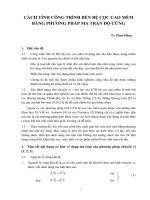
3. Dimention of Box culvert
Cells
Wearing Surface Heigth :
Vertical Depth (a)
4
16.0
cm
44
cm
Cell Clear Width [1,2,3,4]
in direction parallel with traffic
(1)
400.0
400.0
(2)
400.0
400.0
Exterior Wall thickness (5)
30.0
cm
Interior Wall thickness (6)
30.0
cm
Bottom Slab Height (7)
30.0
cm
Top Slab Height (8)
30.0
cm
Cell Clear Height (9)
400.0
cm
Gusset Edge Length (10)
30.0
cm
(3)
400.0
400.0
(4)
400.0
400.0
Height of water:
cm
cm
300.0
10Ф28/10
Ф14/15
Ф14/15
Ф14/15
7Ф28/15
7Ф20/15
7Ф20/15
10Ф25/10
7Ф20/15
10Ф32/10
Ф14/15
10Ф22/10
Parameters
H (cm) :
B (cm) :
Cover (cm) :
D' (mm) :
As.min (cm2) :
(article 5.7.3.3.2)
As.max (cm2):
(article 5.7.3.3.2)
Top Slab
Bottom Slab
Exterior wall
Interior wall
100.0
100.0
100.0
100.0
25.0
25.0
25.0
25.0
6.4
6.4
6.4
6.4
50.6
50.6
50.6
50.6
30.0
5.0
Top Renf.
Ф28
Select Bar mm :
Select Spc. cm :
10
Selected As cm2 : 61.58
Bars Pattern : 10Ф28/10
Select Bar mm :
Select Spc. cm :
Tranverse bars
30.0
30.0
5.0
30.0
5.0
5.0
Bottom Renf.
Top Renf.
Bottom Renf.
Top Renf.
Bottom Renf.
Top Renf.
15
10
10
10
15
15
Ф28
43.10
7Ф28/15
Tranverse bar
Ф14
15
Ф14/15
Ф32
80.42
10Ф32/10
Ф22
38.01
10Ф22/10
Tranverse bar
Ф14
15
Ф14/15
Ф25
Ф20
49.09
21.99
10Ф25/10
7Ф20/15
Tranverse bar
Ф14
15
Ф14/15
Ф20
Bottom Renf.
Ф20
15
21.99
21.99
7Ф20/15
7Ф20/15
Tranverse bar
Ф14
15
Ф14/15
4. Loading
live load
eh
ev
ls
4.1. Dead load
Top Slab Weight :
Bottom Slab Weight :
Exterior Wall Weight :
Interior Wall Weight :
7.85
7.85
29.40
29.40
4.1.1. Vertical earth pressure (EV)
• The factor of vertical earth pressure
0.6
Thick of cover
Covering (h3)
0.16 m
0.44 m
Wearing Surface Load
Backfill
kN/m
kN/m
kN
kN
(A12.11.2.2)
→ Vertical earth pressure on top slab of culvert
→ Fe
γs
eh
Fe = MIN(1+0.2*h3/W,1.15)
=
1.01
EV = Fe.γs.h
EV
(Kn/m)
3.54
7.97
3
(Kn/m )
22.00
18.00
4.1.2. Horizontal earth pressure (EH)
- Basic earth pressure shall be assumed to be linearly proportional to the depth of earth and taken as.
In which:
Ph = Ka*γs*Z
(3.11.5.1-1)
Ph : horizontal earth pressure at the depth of Z (kN/m)
+ Lateral earth pressure applied on the plate as figure
1
Ph = Ka*γs*h3
in which:
Ground level
Slab2
Ph2 = Ka*γs*(H+h3)
- Ph : Horizontal earth pressure (kN/m)
- γs : Density of soil (kN/m3)
γs = 18
- ϕ : Angle of internal friction
ϕ=
30 deg
- h3 : filling height from top of box culvert (m)
#REF!
- H : Total height of box culvert (m)
4.3
- Ka : active earth pressure coefficient (3.11.5.3 - 22TCN 272-05)
Ka
in which:
Ph1
2
sin ( θ
φ)
Γ sin θ .sin( θ
2
Γ
δ)
sin ( φ
1
sin ( θ
ka
0.31
γs
(kN/m3)
18.
Vertical Water Load (5) :
Horizontal Water Load, Top (7) :
Horizontal Water Load, Bottom (7) :
30.00
0.00
0.00
0.60 m
4.1.3. Water effect
H
Ph2
β ) . sin ( φ
δ ) . sin ( θ
δ)
2
β)
0
11
90
30
2.49
0.31
β: Angle of surface (deg)
δ: Friction angle between soil and wall (deg)
θ: Angle between wall and vertical (deg)
φ Intenal friction angle of soil
⇒
Γ=
⇒
Ka
Covering
h3
Ph1
(kN/m)
3.31
Ph2
(kN/m)
27.06
kN/m
kN/m
kN/m
Page: 76
4.2. Live load
- Where the depth of fill is less than 600mm, the effect of fill on the distribution of live load shall be neglected.
• The uniformly distribution of wheel where covering depth >= 600 mm detemined follow A 3.6.1.2.6.
• Impact load detemined follow A 3.6.2.2.
• Where the depth of fill exceeds 600 mm, wheel loads may be consided to be uniformly distributed over rectangular area
with sides equal to the dimension of the tire contact area as A 3.6.1.2.5, and increased by either 1.15 times the depth
of the fill in select granular backfill, or the depth of the fill in all other cases.
• For single span culverts, the effects of live load may be neglected where the depth of fill is >= 2400mm and exceeds
the span length.
• For multiple span culverts, the effects of live load may be neglected where the depth of fill exceeds the distance
between faces of end walls.
• Where such areas from several wheels overlap, the total load shall be uniformly distributed over the area.
• The dynamic load allowance for culverts shall be taken as:
IM= 33*( 1.0 - 4.1x10⁻⁴.De )
( 3.6.2.2.1 )
• Design truck:
- Estimate for impact factor and distributed area of wheel
Covering
Wheel load
IM
(m)
(Kn)
(%)
0.6
72.5
24.88
B
(mm)
510
L
(mm)
181
Be
(mm)
1134
Le
(mm)
805
Distribution of wheel load for 1 lane
Wheel load of Truck : 01 lane
(lane number, Lane factor & IM factor should be applied)
Distribution of wheel load for 2 lane
1800
1200
1800
Wheel load of Truck : 02 lane
(lane number, Lane factor & IM factor should be applied)
→
Number of
lane
1 lane
2 lane
Distributed wheel load of trucks
B
L
(mm)
(mm)
1134
805
1134
805
Truck is consider as concentrated load
Lltruck
(kN/m)
79.46
79.46
.
Page: 77
• Tandem:
Covering
(m)
0.6
Wheel load
(Kn)
55
IM
(%)
24.88
B
(mm)
510
L
(mm)
137
Distribution of wheel load of Tandem for 1 lane
Be
(mm)
1134
Le
(mm)
761
1200
Wheel load of Tandem: 01 Lane
(lane number, Lane factor & IM factor should be applied)
Distribution of wheel load of Tandem for 2 lane
1800
1200
1800
Wheel load of Tandem: 02 Lane
(lane number, Lane factor & IM factor should be applied)
→
Number of
lane
1 lane
2 lane
Distributed wheel load of Tandem
Lltruck
B
L
(mm)
(mm)
(kN/m)
1134
761
63.73
1134
761
63.73
Consider as concentrated load
• Lane load
- Lane load distributed on 1 m
3.100
kN/m2
The equivalent strip widths for Liveload on box culvert (A4.6.2.3)
0.5
E1lane = 250 + 0.42 (L1W1)
- For one Lane:
In which:
- L1: Modified span length
- W1: Modified edge-to-edge width of culvert
- For multi Lane:
→ E1lane
Emultilane = 2100 + 0.12 (L1W1)0.5 ≤ W/NL
- W: Physical edge-to-edge width ofculvert
- NL: Number of lanes
=
=
=
4300.00 mm
8000.00 mm
2713.36 mm
=
=
8000.00 mm
2
→ Emultilane =
2803.82 mm
Es =
2713.36 mm
The width of interior equivalent strip
4.2.1. Surcharge load (LS)
-Where a surcharge load is present, a constant horizontal earth pressure shall be added to the basic earth pressure.
This constant earth pressure may be taken as
∆P =
k.γs.heq
(3.11.6.1-1)
Where:
k=
active coefficient of earth pressure
density of soil (kN/m3)
γs =
heq =
→ heq =
→ ∆p =
height of soil equivalent to design truck (m). Determine from table 3.11.6.2-1, 22TCN 272-05
Depend on the height of wall:
4.300
m
1.009
m
5.574
kN/m2
Page: 78
4.3 Load combination
Load combination and load combination factor shall be taken as Table 3.4.1-1
Table of load combination factor
State
Dead load of structural
Dead load of wearing
Vertical earth pressure
Horizontal earth pressure
Water load
Live load surcharge
Live load
Mark Str. I-A Str. I-B Str. I-C Str. III-A Str. III-B Str. III-C Service I
DC
1.25
1.25
0.90
1.25
1.25
0.90
1.00
DW
1.50
1.50
0.65
1.50
1.50
0.65
1.00
EV
1.30
1.30
0.90
1.30
1.30
0.90
1.00
EH
1.50
0.90
1.50
1.50
0.90
1.50
1.00
WA
1.00
1.00
1.00
1.00
1.00
1.00
1.00
LS
1.75
1.75
1.75
1.35
1.35
1.35
1.00
1.75
1.75
1.75
1.35
1.35
1.35
1.00
LL
Table of load combination on a unit length of culvert (kN/m)
State
Mark Str. I-A Str. I-B Str. I-C Str. III-A Str. III-B Str. III-C Service I
DC 26.64 26.64 19.18
26.64
26.64
19.18
21.31
Top Slab Weight
DC 26.64 26.64 19.18
26.64
26.64
19.18
21.31
Bottom Slab Weight
EV 28.13 28.13 19.47
28.13
28.13
19.47
21.64
Vertical earth pressure
DW 14.42 14.42
6.25
14.42
14.42
6.25
9.62
Dead load of wearing
WA 81.40 81.40 81.40
81.40
81.40
81.40
81.40
Vertical Water Load
WA
0.00
0.00
0.00
0.00
0.00
0.00
0.00
Horizontal Water Load (bottom)
EH 13.49
8.09
13.49
13.49
8.09
13.49
8.99
Horizontal earth pressure at top
96.65
57.99
96.65
64.43
Increase Hor. earth pressure at bot. EH 96.65 57.99 96.65
LS 26.47 26.47 26.47
20.42
20.42
20.42
15.12
Live load surcharge
Load Vertical Effect
11.36
11.36
11.36
8.41
LL 14.72 14.72 14.72