tài liệu chuẩn đoán ,bảo dưỡng động cơ 2AZfe lắp trên xe camry
Bạn đang xem bản rút gọn của tài liệu. Xem và tải ngay bản đầy đủ của tài liệu tại đây (2.68 MB, 85 trang )
14–1
ENGINE MECHANICAL
–
ENGINE ASSEMBLY (2AZ–FE)
ENGINE ASSEMBLY (2AZ–FE)
1404R–02
INSPECTION
1.
2.
3.
INSPECT COOLANT (See page 16–20)
INSPECT ENGINE OIL
INSPECT BATTERY
4.
Standard specific gravity: 1.25 – 1.29 at 20_C (68_F)
INSPECT AIR CLEANER FILTER ELEMENT SUB–ASSY
5.
6.
INSPECT SPARK PLUG
(See page 18–1)
INSPECT V–RIBBED BELT
7.
(a)
(b)
INSPECT IGNITION TIMING
Warm up engine.
When using hand–held tester.
(1) Connect the hand–held tester to the DLC3.
Ignition timing: 8 – 12_ BTDC
HINT:
Please refer to the hand–held tester operator’s manual for further details.
(c) When not using hand–held tester.
(1)
TC
CG
A51075
A52004
Using SST, connect terminals 13 (TC) and 4 (CG)
of DLC3.
SST 09843–18040
NOTICE:
S
Be sure not to connect incorrectly. It causes breakage
of the engine.
S
Turn OFF all electrical systems.
S
Operate the inspection when the cooling fan motor is
turned OFF.
(2) Remove the cylinder head cover No.2.
(3) Pull out the wire harness as shown in the illustration.
Connect the clip of the timing light to the engine.
NOTICE:
S
Use a timing light which can detect the first signal.
S
After checking, be sure to tape the wire harness.
(4) Inspect ignition timing at idle.
Ignition timing: 8 – 12_ BTDC
NOTICE:
When checking the ignition timing, the transmission is at
neutral position.
HINT:
After engine rpm is kept at 1,000 – 1,300 r/min. for 5 seconds,
check that it returns idle speed.
2002 CAMRY REPAIR MANUAL (RM881U)
AuthorĂ:
DateĂ:
1523
14–2
ENGINE MECHANICAL
–
ENGINE ASSEMBLY (2AZ–FE)
(5) Disconnect terminals 13 (TC) and 4 (CG) of DLC3.
(6) Inspect ignition timing at idle.
Ignition timing: 5 – 15_ BTDC
(7) Confirm that ignition timing moves to advanced
angle side when the engine rpm is increased.
(8) Remove the timing light.
8.
INSPECT ENGINE IDLE SPEED
(a) Warm up engine.
(b) When using hand–held tester.
(1) Connect the hand–held tester to the DLC3.
Idle speed:
A/T 610 – 710 r/min.
M/T 650 – 750 r/min.
NOTICE:
S
Check idle speed with cooling fan OFF.
S
Switch off all accessories and air conditioning.
HINT:
Please refer to the hand–held tester operator’s manual for further details.
(c)
When not using hand–held tester.
(1) Using SST, connect tachometer test prove to terminal 9 (TAC) of DLC3.
SST 09843–18040
(2) Check the idle speed.
Idle speed:
A/T 610 – 710 r/min.
M/T 650 – 750 r/min.
9.
(a)
(b)
(c)
(d)
(e)
INSPECT COMPRESSION
Warm up and stop engine.
Disconnect the injector connectors.
Remove ignition coils.
Remove spark plugs.
Inspect cylinder compression pressure.
(1) Insert a compression gauge into the spark plug
hole.
(2) Fully open the throttle.
TAC
A52006
A01037
2002 CAMRY REPAIR MANUAL (RM881U)
AuthorĂ:
DateĂ:
1524
14–3
ENGINE MECHANICAL
–
ENGINE ASSEMBLY (2AZ–FE)
(3)
While cranking the engine, measure the compression pressure.
Compression pressure:
1.360 MPa (13.9 kgf/cm2, 198 psi)
Minimum pressure:
0.98 MPa (10 kgf/cm2, 142 psi)
Difference between each cylinder:
100 kPa (1.0 kgf/cm2, 14 psi)
NOTICE:
S
Always use a fully charged battery to obtain engine
speed of 250 rpm or more.
S
Check other cylinder’s compression pressure in the
same way.
S
This measurement must be done in as short a time as
possible.
(4) If the cylinder compression is low, pour a small
amount of engine oil into the cylinder through the
spark plug hole and inspect again.
HINT:
S
If adding oil increases the compression, it is likely that the
piston rings and/or cylinder bore are worn or damaged.
S
If pressure stays low, a valve may be sticking or seating
improperly, or there may be leakage past the gasket.
10. INSPECT CO/HC
(a) Start the engine.
(b) Race engine at 2,500 r/min for approx. 180 seconds.
(c) Insert CO/HC meter testing probe at least 40 cm (1.3 ft) into tailpipe during idling.
(d) Immediately check CO/HC concentration at idle and/or 2,500 r/min.
HINT:
S
Complete the measuring within 3 minutes.
S
When doing the 2 mode (idle and 2,500 r/min.) test, these measuring orders are prescribed by the applicable local regulations.
(e) If the CO/HC concentration does not comply with regulations, troubleshoot in the order given below.
(1) Check heated oxygen sensor operation. (See page 12–1)
(2) See the table below for possible causes, and then inspect and correct the applicable causes if
necessary.
2002 CAMRY REPAIR MANUAL (RM881U)
AuthorĂ:
DateĂ:
1525
14–4
ENGINE MECHANICAL
CO
Normal
Low
High
HC
High
High
High
–
ENGINE ASSEMBLY (2AZ–FE)
Problems
Causes
Rough idle
1. Faulty ignitions:
S Incorrect timing
S Fouled, shorted or improperly gapped plugs
2. Incorrect valve clearance
3. Leaky intake and exhaust valves
4. Leaky cylinders
Rough idle
(Fluctuating HC reading)
1. Vacuum leaks:
S PCV hoses
S Intake manifold
S Throttle body
S ISC valve
S Brake booster line
2. Lean mixture causing misfire
Rough idle
(Black smoke from exhaust)
1. Restricted air filter
2. Plugged PCV valve
3. Faulty EFI systems:
S Faulty pressure regulator
S Defective water temperature sensor
S DEFECTIVE Air–flow meter
S Faulty ECU
S Faulty injectors
S Faulty throttle position sensor
2002 CAMRY REPAIR MANUAL (RM881U)
AuthorĂ:
DateĂ:
1526
14–5
ENGINE MECHANICAL
–
FAN AND GENERATOR V BELT (2AZ–FE)
FAN AND GENERATOR V BELT (2AZ–FE)
1405U–02
REPLACEMENT
1.
2.
REMOVE FRONT WHEEL RH
REMOVE FRONT FENDER APRON SEAL RH
3.
REMOVE ENGINE COVER SUB–ASSY NO.1
4.
(a)
REMOVE ENGINE MOVING CONTROL ROD
W/BRACKET
Remove the 3 bolts and engine mounting control rod w/
bracket.
A59888
5.
REMOVE ENGINE MOUNTING STAY NO.2 RH
6.
REMOVE ENGINE MOUNTING BRACKET NO.2 RH
SST
7.
REMOVE FAN AND GENERATOR V BELT
(a)
Slowly turn the drive belt tensioner clockwise in more than
3 seconds, and remove the drive bolt by using SST.
SST 09249–63010
8.
INSTALL FAN AND GENERATOR V BELT
(a)
Slowly turn the drive belt tensioner clockwise in more than
3 seconds, and install the drive bolt by using SST.
SST 09249–63010
A62240
SST
A62240
9.
INSTALL ENGINE MOUNTING BRACKET NO.2 RH
Torque: 52 N⋅m (531 kgf⋅cm, 38 ft⋅lbf)
2002 CAMRY REPAIR MANUAL (RM881U)
AuthorĂ:
DateĂ:
1527
14–6
ENGINE MECHANICAL
10.
–
FAN AND GENERATOR V BELT (2AZ–FE)
INSTALL ENGINE MOUNTING STAY NO.2 RH
Torque: 64 N⋅m (653 kgf⋅cm, 47 ft⋅lbf)
11.
(a)
INSTALL ENGINE MOVING CONTROL ROD
W/BRACKET
Install the engine mounting control rod with the 3 bolts w/
bracket.
Torque: 64 N⋅m (653 kgf⋅cm, 47 ft⋅lbf)
A59888
12.
INSTALL FRONT WHEEL RH
Torque: 103 N⋅m (1,050 kgf⋅cm, 76 ft⋅lbf)
2002 CAMRY REPAIR MANUAL (RM881U)
AuthorĂ:
DateĂ:
1528
14–7
ENGINE MECHANICAL
–
VALVE CLEARANCE (2AZ–FE)
VALVE CLEARANCE (2AZ–FE)
1405V–02
ADJUSTMENT
1.
REMOVE FRONT WHEEL RH
2.
REMOVE FRONT FENDER APRON SEAL RH
3.
REMOVE ENGINE COVER SUB–ASSY NO.1
4.
REMOVE IGNITION COIL ASSY
5.
DISCONNECT VENTILATION HOSE
6.
DISCONNECT VENTILATION HOSE NO.2
7.
DISCONNECT ENGINE WIRE
8.
REMOVE CYLINDER HEAD COVER SUB–ASSY
(a)
Remove the bolt and disconnect the engine wire harness
clamp.
Remove the 8 bolts, 2 nuts, cylinder head cover and gasket.
(b)
A52450
9.
(a)
Timing Marks
(b)
SET NO.1 CYLINDER TO TDC/COMPRESSION
Turn the crankshaft pulley, and align its groove with the
timing mark ”0” of the timing chain cover.
Check that the timing marks of the camshaft timing
sprockets are aligned with the timing marks of the No.1
bearing cap as shown in the illustration.
Timing Marks
Groove
A52504
AuthorĂ:
DateĂ:
1529
14–8
ENGINE MECHANICAL
–
VALVE CLEARANCE (2AZ–FE)
10. INSPECT VALVE CLEARANCE
HINT:
Inspect and adjust the valve clearance when the engine is cold.
(a)
No. 1 Cylinder TDC/Compression
IN
EX
A52469
(b)
(c)
No. 4 Cylinder TDC/Compression
IN
EX
Paint Mark
A52470
Paint Mark
Timing Mark
Timing Mark
Groove
A52471
Loosen
Check only the valve indicated.
(1) Using a feeler gauge, measure the clearance between the valve lifter and camshaft.
(2) Record the out–of specification valve clearance
measurements. They will be used later to determine
the required replacement adjusting shim.
Valve clearance (Cold):
Intake 0.19 – 0.29 mm (0.0075 – 0.0114 in.)
Exhaust 0.30 – 0.40 mm (0.0118 – 0.0157 in.)
Turn the crankshaft clockwise 1 revolution (360_) and set
No.4 cylinder to TDC/compression.
Check only the valve indicated.
(1) Using a feeler gauge, measure the clearance between the valve lifter and camshaft.
(2) Record the out–of specification valve clearance
measurements. They will be used later to determine
the required replacement adjusting shim.
Valve clearance (Cold):
Intake 0.19 – 0.29 mm (0.0075 – 0.0114 in.)
Exhaust 0.30 – 0.40 mm (0.0118 – 0.0157 in.)
11. ADJUST VALVE CLEARANCE
NOTICE:
Be sure not to turn the crankshaft without the chain tensioner.
(a) Turn the crankshaft clockwise 1 revolution (360_) and set
the No.1 cylinder to the TDC/compression.
(b) Place matchmarks on the timing chain and camshaft timing gear.
(c) Remove the 2 bolts and chain tensioner.
(d)
Fix the camshaft with a spanner and so on, then loosen
the camshaft timing gear set bolt.
NOTICE:
Be careful not to damage the valve lifter.
Fix
A52454
AuthorĂ:
DateĂ:
1530
14–9
ENGINE MECHANICAL
1
3
5
4
2
–
VALVE CLEARANCE (2AZ–FE)
(e)
Loosen the camshaft bearing cap bolts on No.2 camshaft
in the sequence shown in the illustration in several
passes, and remove the caps.
(f)
(g)
Raising the camshaft, remove the set bolt.
Remove the timing chain sprocket from the camshaft with
timing chain.
Remove the timing chain sprocket from the timing chain.
A32636
(h)
A52473
1
3
5
4
(i)
2
(j)
Loosen the camshaft bearing cap bolts on camshaft in the
sequence shown in the illustration in several passes, and
remove the caps.
Remove the intake camshaft.
A36526
(k) Tie the timing chain with a string.
NOTICE:
Be careful not to drop anything inside the timing chain cover.
(l)
Remove the valve lifers.
A52474
(m)
Using a micrometer, measure the thickness of the removed lifter.
A01082
AuthorĂ:
DateĂ:
1531
14–10
ENGINE MECHANICAL
(n)
–
VALVE CLEARANCE (2AZ–FE)
Calculate the thickness of a new lifter so that the valve
clearance comes within the specified value.
A
Thickness of new lifter
B
Thickness of used lifter
C
Measured valve clearance
Valve clearance:
Intake A = B + (C – 0.24 mm (0.0094 in.))
Exhaust: A = B + (C – 0.35 mm (0.0138 in.))
EXAMPLE: (Intake)
Measured valve clearance = 0.44 mm (0.0173 in.)
0.44 mm (0.0173 in.) – 0.24 mm (0.0094 in.) = 0.20 mm (0.0079 in.)
(Measured – Specification = Excess clearance)
Used shim measurement = 5.30 mm (0.2087 in.)
0.20 mm (0.0079 in.) + 5.30 mm (0.2087 in.) = 5.50 mm (0.2165 in.)
(Excess clearance + Used shim = Ideal new shim)
Closest new shim = 5.50 mm (0.2165 in.) = Shim No. ”50”
(1) Select a new lifter with a thickness as close as possible to the calculated values.
HINT:
S
Lifters are available in 35 sizes in increments of 0.020 mm
(0.0008 in.), from 5.060 mm (0.1992 in.) to 5.740 mm
(0.2260 in.).
S
Refer to valve lifter selection chart on the following 2
pages.
AuthorĂ:
DateĂ:
1532
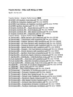
Valve Lifter Selection Chart (Intake)
N
AuthorĂ:
DateĂ:
A77296
1533
Intake valve clearance (Cold):
0.19 to 0.29 mm (0.008 to 0.011 in.)
EXAMPLE:
The 5.250 mm (0.2067 in.) lifter is installed, and the measured
clearance is 0.400 mm (0.0157 in.). Replace the 5.250 mm
(0.2067 in.) lifter with a new No. 42 lifter.
Lifter
No.
Thickness
Lifte
No.
06
5.060 (0.1992)
30
08
5.080 (0.2000)
32
10
5.100 (0.2008)
34
12
5.120 (0.2016)
36
14
5.140 (0.2024)
38
16
5.160 (0.2031)
40
18
5.180 (0.2039)
42
20
5.200 (0.2047)
44
22
5.220 (0.2055)
46
24
5.240 (0.2063)
48
26
5.260 (0.2071)
50
28
5.280 (0.2079)
52
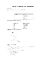
Valve Lifter Selection Chart (Exhaust)
Lifter
AuthorĂ:
No.
DateĂ:
A77297
1534
Exhaust valve clearance (Cold):
0.30 to 0.40 mm (0.012 to 0.016 in.)
EXAMPLE:
The 5.340 mm (0.2102 in.) lifter is installed, and the measured
clearance is 0.440 mm (0.0173 in.). Replace the 5.340 mm
(0.2102 in.) lifter with a new No. 44 lifter.
06
5.
08
5.
10
5.
12
5.
14
5.
16
5.
18
5.
20
5.
22
5.
24
5.
26
5.
28
5.
14–13
ENGINE MECHANICAL
Paint Mark
–
VALVE CLEARANCE (2AZ–FE)
(o)
Install the timing chain on the camshaft timing gear, with
the painted links aligned with the timing marks on the
camshaft timing sprockets.
(p)
Examine the front marks and numbers and tighten the
bolts in the order shown in the illustration.
Torque:
Bearing cap No. 1 30 N⋅m (301 kgf⋅cm, 22 ft⋅lbf)
Bearing cap No. 3 9.0 N⋅m (92 kgf⋅cm, 80 in.⋅lbf)
(q)
Put the camshaft No.2 on the cylinder head with the
painted links of chain aligned with the timing mark on the
camshaft timing sprockets.
(r)
Raising the camshaft, tighten the set bolt temporarily.
(s)
Examine the from marks and numbers and tighten the
bolts in the sequence shown in the illustration.
Torque:
Bearing cap No. 2 30 N⋅m (301 kgf⋅cm, 22 ft⋅lbf)
Bearing cap No. 3 9.0 N⋅m (92 kgf⋅cm, 80 in.⋅lbf)
Timing Marks
A52456
5
3
1
Bearing Cap No. 1
2
4
Bearing Cap No. 3
A52457
Paint Mark
Timing Mark
A53011
A52473
Bearing Cap No. 2 Bearing Cap No. 3
5
3
1
2
4
A52458
AuthorĂ:
DateĂ:
1535
14–13–1
ENGINE MECHANICAL
Tighten
–
VALVE CLEARANCE (2AZ–FE)
(t)
Fix the camshaft with a spanner and so on, then tighten
the camshaft timing gear set bolt.
Torque: 54 N⋅m (551 kgf⋅cm, 40 ft⋅lbf)
NOTICE:
Be careful not to damage the valve lifter.
Fix
A52459
(u)
As shown in the illustration, check the matchmarks on the
timing chain and camshaft timing sprockets and the alignment of the pulley groove with timing mark of the chain
cover.
(v)
Install chain tensioner.
(1) Release the ratchet pawl, fully push in the plunger
and apply the hook to the pin so that the plunger
cannot spring out.
7 Links
Paint Mark
Paint Mark
Timing Marks
Timing Mark
Groove
A52460
Raise
Push
Pin
Hook
A52461
(2)
Install a new gasket and chain tensioner with the 2
nuts.
Torque: 9.0 N⋅m (92 kgf⋅cm, 80 in.⋅lbf)
NOTICE:
When installing the tensioner, set the hook again if the
hook releases the plunger.
Engine
Front
A52462
AuthorĂ:
DateĂ:
1536
14–13–2
ENGINE MECHANICAL
–
VALVE CLEARANCE (2AZ–FE)
(3)
Turn the crankshaft counterclockwise, and disconnect the plunger knock pin from the hook.
(4)
Turn the crankshaft clockwise, and check that the
slipper is pushed by the plunger.
Disconnect
Hook
Pin
Turn
A52463
Plunger
Push
Turn
A52464
12.
INSTALL CYLINDER HEAD COVER SUB–ASSY
(a)
Remove any old packing (FIPG) material.
(b)
Apply seal packing to 2 locations as shown in the illustration.
Seal packing: Part No. 08826–00080 or equivalent
NOTICE:
S
Remove any oil the contact surface.
S
Install the cylinder head cover within 5 minutes after
applying seal packing.
S
Do not put into engine oil 2 hours after installing.
Seal Packing
A53051
(c)
Nut
13.
14.
15.
Install the cylinder head cover with the 8 bolts and 2 nuts.
Torque: 11 N⋅m (110 kgf⋅cm, 8 ft⋅lbf)
Nut
A61989
INSTALL IGNITION COIL ASSY
Torque: 9.0 N⋅m (92 kgf⋅cm, 80 in.⋅lbf)
INSTALL FRONT WHEEL RH
Torque: 103 N⋅m (1,050 kgf⋅cm, 76 ft⋅lbf)
INSPECT OIL LEAK
AuthorĂ:
DateĂ:
1537
14–14
ENGINE MECHANICAL
–
PARTIAL ENGINE ASSY (2AZ–FE)
PARTIAL ENGINE ASSY (2AZ–FE)
140HS–01
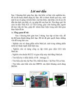
COMPONENTS
Engine Moving Control Rod w/ Bracket
64 (653, 47)
Engine Cover Sub–Assy No. 1
52 (531, 38)
Engine Mounting
Bracket No. 2 RH
64 (653, 47)
Engine Mounting
Stay No. 2 RH
Fan and Generator
V Belt
Heater Inlet Water Hose
52 (531, 38)
21 (214, 15)
Generator Assy
25 (250, 18)
Radiator Hose Inlet
Compressor and
Magnetic Clutch
ABS R/B
Radiator Hose Outlet
Engine Under
Cover RH
Heater Outlet Water Hose
Air Cleaner
Inlet Assy
Air Cleaner Assy
Engine Under
Cover LH
Air Cleaner Bracket
Battery
Battery Tray
N⋅m (kgf⋅cm, ft⋅lbf)
: Specified torque
A60079
2002 CAMRY REPAIR MANUAL (RM881U)
AuthorĂ:
DateĂ:
1538
14–15
ENGINE MECHANICAL
–
PARTIAL ENGINE ASSY (2AZ–FE)
M/T:
Floor Shift Cable
Transmission Control Shift
Front Fender Apron Seal LH
Clutch Release Cylinder
Steering Intermediate
Shaft Sub–Assy
35 (357, 26)
Oil Reservoir Hose
Return Tube
Floor Shift Cable
Transmission Control Shift
(A/T)
Tie Rod Assy LH
15 (150, 11)
49 (500, 36)
8 (82, 71 in.⋅lbf)
Speed Sensor
Front LH
z 294 (3,000, 217)
Front Axle Hub LH Nut
Oil Cooler Hose
127 (1,295, 94)
z Exhaust Pipe Gasket
Exhaust Pipe Assy Front
Front Suspension Arm
Sub–Assy Lower No.1 LH
56 (571, 41)
z
z
z Exhaust Pipe Gasket
62 (633, 46)
Exhaust Pipe No. 1
Support Bracket
33 (337, 24)
z
N⋅m (kgf⋅cm, ft⋅lbf)
Exhaust Pipe No. 1
Support Bracket
33 (337, 24)
: Specified torque
z Non – reusable part
A60078
2002 CAMRY REPAIR MANUAL (RM881U)
AuthorĂ:
DateĂ:
1539
14–16
ENGINE MECHANICAL
–
PARTIAL ENGINE ASSY (2AZ–FE)
A/T:
43 (439, 31)
54 (551, 40)
95 (969, 70)
Vane Pump Assy
Transverse Engine Engine Mounting Bracket
95 (969, 70)
87 (888, 64)
Front Frame Assy
Frame Side Rail
Plate Sub–Assy RH
Frame Side Rail Plate
Sub–Assy LH
32 (326, 24)
Frame Suspension
Member Brace Rear RH
85 (867, 63)
Frame Suspension
Member Brace Rear LH
N⋅m (kgf⋅cm, ft⋅lbf)
32 (326, 24)
85 (867, 63)
: Specified torque
A60070
2002 CAMRY REPAIR MANUAL (RM881U)
AuthorĂ:
DateĂ:
1540
14–17
ENGINE MECHANICAL
–
PARTIAL ENGINE ASSY (2AZ–FE)
M/T:
43 (439, 31)
89 (910, 66)
Engine Mounting
Bracket Rear No. 2
54 (551, 40)
64 (653, 47)
95 (969, 70)
Vane Pump Assy
Transverse Engine Engine Mounting Bracket
87 (888, 64)
143 (1,459, 106)
Front Frame Assy
Frame Side Rail
Plate Sub–Assy RH
Frame Side Rail Plate
Sub–Assy LH
Frame Suspension
Member Brace Rear LH
85 (867, 63)
32 (326, 24)
Frame Suspension
Member Brace Rear LH
N⋅m (kgf⋅cm, ft⋅lbf)
32 (326, 24)
85 (867, 63)
: Specified torque
A59886
2002 CAMRY REPAIR MANUAL (RM881U)
AuthorĂ:
DateĂ:
1541
14–18
ENGINE MECHANICAL
–
PARTIAL ENGINE ASSY (2AZ–FE)
A/T:
Front Drive Shalt Assy RH
64 (653, 47)
Drive Shaft Bearing Bracket
Flywheel Housing Under Cover
Drive Plate
Spacer Front 44 (450, 32)
Drive Plate and Ring
Gear Sub–Assy
Engine Wire
98 (1,000, 72)
41 (418, 30)
64 (650, 47)
Drive Plate
Spacer Rear
Automatic Transaxle Assy
46 (470, 34)
Starter Assy
Front Drive Shaft Assy LH
39 (398, 29)
N⋅m (kgf⋅cm, ft⋅lbf)
: Specified torque
A60075
2002 CAMRY REPAIR MANUAL (RM881U)
AuthorĂ:
DateĂ:
1542
14–19
ENGINE MECHANICAL
–
PARTIAL ENGINE ASSY (2AZ–FE)
M/T:
Front Drive Shalt Assy RH
64 (653, 47)
Engine Mounting Bracket Rear
44 (450, 32)
Engine Wire
13 (1,330, 96)
19 (195, 14)
64 (560, 47)
Flywheel Sub–Assy
Clutch Disc Assy
46 (470, 34)
Clutch Cover Assy
64 (650, 47)
46 (470, 34)
Manual Transaxle Assy
Front Drive Shaft Assy LH
Starter Assy
39 (398, 29)
N⋅m (kgf⋅cm, ft⋅lbf)
: Specified torque
A60074
2002 CAMRY REPAIR MANUAL (RM881U)
AuthorĂ:
DateĂ:
1543
14–20
ENGINE MECHANICAL
–
PARTIAL ENGINE ASSY (2AZ–FE)
9 (92, 80 in.⋅lbf)
30 (306, 12)
Intake Manifold
Ignition Coil Assy
z Intake Manifold To Head Gasket
30 (306, 12)
Intake Manifold Insulator No. 1
Ventilation Hose
Ventilation Hose No. 2
V–ribbed Belt Tensioner Assy
12 (122, 9)
Manifold Converter
Insulator No. 1
59.5 (607, 44)
12 (122, 9)
z Exhaust Manifold To Head Gasket
37 (378, 27)
Exhaust Manifold Converter Sub–assy
Manifold Stay
44 (449, 32)
44 (449, 32)
Manifold Stay No.2
N⋅m (kgf⋅cm, ft⋅lbf) : Specified torque
z Non – reusable part
A60090
2002 CAMRY REPAIR MANUAL (RM881U)
AuthorĂ:
DateĂ:
1544
14–21
ENGINE MECHANICAL
–
PARTIAL ENGINE ASSY (2AZ–FE)
20 (204, 15)
Fuel Delivery Pipe
w/ Injector
Knock Control Sensor
Engine Oil Pressure Switch Assy
39 (398, 29)
15 (153, 11)
Water Temperature Sensor
20 (208, 15)
Water By–pass Pipe No. 1
Oil Level Gage
9 (92, 80 in.⋅lbf)
9 (92, 80 in.⋅lbf)
z Gasket
Oil Level Gage Guide
z Oil Level Gage Guide O–ring
Oil Level Gage
TMMK Made:
9 (92, 80 in.⋅lbf)
Thermostat
9 (92, 80 in.⋅lbf)
Water Inlet
9 (92, 80 in.⋅lbf)
z Gasket
z Water Housing Gasket No. 1
N⋅m (kgf⋅cm, ft⋅lbf) : Specified torque
z Non – reusable part
Oil Level Gage Guide
z Oil Level Gage
Guide O–ring
A62235
2002 CAMRY REPAIR MANUAL (RM881U)
AuthorĂ:
DateĂ:
1545
14–74
ENGINE MECHANICAL
–
CHAIN (2AZ–FE)
CHAIN (2AZ–FE)
140HV–01
REPLACEMENT
1.
REMOVE HOOD SUB–ASSY
2.
3.
REMOVE FRONT WHEEL RH
REMOVE ENGINE UNDER COVER LH
4.
REMOVE ENGINE UNDER COVER RH
5.
REMOVE FRONT FENDER APRON SEAL RH
6.
(a)
DRAIN ENGINE OIL
Install a new gasket and the drain plug after draining engine oil.
Torque: 25 N⋅m (255 kgf⋅cm, 18 ft⋅lbf)
REMOVE EXHAUST PIPE ASSY FRONT
7.
8.
(a)
REMOVE ENGINE MOVING CONTROL ROD
W/BRACKET
Remove the 3 bolts and engine moving control rod w/
bracket.
A59888
9.
REMOVE ENGINE MOUNTING STAY NO.2 RH
10.
REMOVE ENGINE MOUNTING BRACKET NO.2 RH
11.
12.
REMOVE FAN AND GENERATOR V BELT
(See page 14–5)
REMOVE ENGINE COVER SUB–ASSY NO.1
13.
DISCONNECT ENGINE WIRE
14.
REMOVE GENERATOR ASSY
15.
REMOVE VANE PUMP ASSY
(See page 51–8)
NOTICE:
Do not disconnect the hose.
16. REMOVE IGNITION COIL ASSY
17.
DISCONNECT VENTILATION HOSE
2002 CAMRY REPAIR MANUAL (RM881U)
AuthorĂ:
DateĂ:
1598
14–75
ENGINE MECHANICAL
18.
–
CHAIN (2AZ–FE)
DISCONNECT VENTILATION HOSE NO.2
19.
REMOVE CYLINDER HEAD COVER SUB–ASSY
(a)
Remove the bolt and disconnect the engine wire harness
clamp.
Remove the 8 bolts and 2 nuts, and disconnect the cylinder head cover.
(b)
A52450
20.
SET NO.1 CYLINDER TO TDC/COMPRESSION (See page 14–7)
21.
REMOVE CRANKSHAFT PULLEY
(a)
Remove the crankshaft pulley (TMC made).
(1) Using SST, loosen the pulley bolt.
SST 09213–54015 (91651–60855), 09330–00021
SST
A52485
(2) Using SST, remove the crankshaft pulley.
SST 09950–50013 (09951–05010, 09952–05010,
09953–05020, 09954–05021)
SST
A36685
(b)
Remove the crankshaft pulley (TMMK made).
(1) Using SST, loosen the pulley bolt.
SST 09960–10010 (09962–01000, 09963–01000)
SST
A62057
2002 CAMRY REPAIR MANUAL (RM881U)
AuthorĂ:
DateĂ:
1599