Tài liệu đào tạo về cảm biến và bộ chấp hành trên xe Ford
Bạn đang xem bản rút gọn của tài liệu. Xem và tải ngay bản đầy đủ của tài liệu tại đây (2.86 MB, 95 trang )
Curriculum Training
Sensors and Actuators
Actuators
Technical Service Training
CG 8234/S en 12/2006
TC4012042H
To the best of our knowledge, the illustrations, technical information, data and descriptions in this issue were correct at the time
of going to print. The right to change prices, specifications, equipment and maintenance instructions at any time without notice
is reserved as part of FORD policy of continuous development and improvement for the benefit of our customers.
No part of this publication may be reproduced, stored in a data processing system or transmitted in any form, electronic,
mechanical, photocopy, recording, translation or by any other means without prior permission of Ford-Werke GmbH. No liability
can be accepted for any inaccuracies in this publication, although every possible care has been taken to make it as complete and
accurate as possible.
Copyright ©2007
Ford-Werke GmbH
Service training programs D-F/GT1 (GB)
Preface
Present-day automotive engineering is becoming more and more complex. During development activities, ever
greater consideration has to be given to the environment and natural resources. For this reason, closed and open-loop
control systems are increasingly finding application in modern automotive engineering.
Actuators are used for the closed and open-loop control of a variety of electronic vehicle systems related, for
example, to the engine, chassis, safety and comfort.
Actuators convert electrical energy into mechanical work (movement) and are used in electromechanical adjustment
systems.
They can be used either purely as actuators, or as components in a closed or open-loop control circuit.
Currently, the most frequently used actuators in motor vehicles are electric motors and solenoids.
Based on the sensor signals they receive, the control modules calculate the variables for the control and consequently
the activation of actuators.
In some cases, actuators are combined with sensors or integrated as complete systems which include a control
module. As a result the testing or replacement of individual actuators is often no longer possible.
Self-tests performed by control modules increasingly account for connected actuators and the related wiring.
Diagnosis is also performed using WDS ( Worldwide Diagnostic System)/IDS (Integrated Diagnostic System).
The procedures and tests described in the Student Information relate to the electrical operation of the individual
actuators. Before performing the electrical tests, ensure that the malfunction is not the result of a mechanical fault.
The training course on sensors and actuators includes the following information for technicians:
–
Sensors, CG 8233/S (TC4012041H)
–
Actuators, CG 8234/S (TC4012042H)
–
Communications Network, CG 8235/S (TC4012053)
Note: The supplied data and values only serve as demonstration and to facilitate understanding. Current
values should always be taken from current workshop literature.
Please remember that our training literature has been prepared for FORD TRAINING PURPOSES only. Repairs
and adjustments MUST always be carried out according to the instructions and specifications in the workshop
literature. Please make full use of the training offered by Ford Technical Training Courses to gain extensive
knowledge of both theory and practice.
Service Training (G522585)
1
Table of Contents
PAGE
Preface..............................................................................................................................
1
Lesson 1 – General Information
Open and closed-loop control.........................................................................................................................................
5
Pulse width modulated signals........................................................................................................................................
6
Solenoids......................................................................................................................................................
7
General............................................................................................................................................................................
7
Testing and measurement................................................................................................................................................
7
Electric motors............................................................................................................................................
8
General............................................................................................................................................................................
8
Motor versions................................................................................................................................................................
9
Actuator motor................................................................................................................................................................
10
Testing and measurement................................................................................................................................................
11
Piezoelectricity............................................................................................................................................
12
The piezo-electric effect..................................................................................................................................................
12
Pyrotechnics................................................................................................................................................
14
General............................................................................................................................................................................
14
Design and operation......................................................................................................................................................
14
Testing and measurement................................................................................................................................................
15
OSC mode....................................................................................................................................................
16
General............................................................................................................................................................................
16
Test questions..............................................................................................................................................
17
Lesson 2 – Actuators
Exhaust gas recirculation (EGR) valves...................................................................................................
2
18
Service Training
Table of Contents
Actuator motor-controlled EGR valve (DC motor)........................................................................................................
18
Actuator motor-controlled EGR valve (stepper motor)..................................................................................................
20
EGR valve (vacuum-controlled).....................................................................................................................................
22
Intake manifold runner control (IMRC) electric motor..................................................................................................
24
Swirl plate actuator.........................................................................................................................................................
25
Throttle plate actuator motor...........................................................................................................................................
27
Fuel injector (petrol engines)..........................................................................................................................................
29
Fuel injector (diesel engines)..........................................................................................................................................
31
Electronic parking brake actuator...................................................................................................................................
33
Electronic throttle plate...................................................................................................................................................
35
Electrical turbocharger guide vane adjustment actuator.................................................................................................
37
Electrically heated thermostat.........................................................................................................................................
39
Window regulator motor.................................................................................................................................................
40
Roof opening panel motor...............................................................................................................................................
40
Parking brake actuator (TRW)........................................................................................................................................
42
Blower motor..................................................................................................................................................................
44
Glow plugs......................................................................................................................................................................
46
Heater control valve........................................................................................................................................................
49
Air conditioning clutch...................................................................................................................................................
51
Instrument cluster............................................................................................................................................................
53
Fuel metering valve.........................................................................................................................................................
55
Fuel pressure control valve.............................................................................................................................................
57
Engine cooling fan..........................................................................................................................................................
59
Clutch actuator................................................................................................................................................................
61
Gearshift actuator............................................................................................................................................................
61
Idle air control (IAC) valve.............................................................................................................................................
63
Variable camshaft timing solenoid valves.......................................................................................................................
65
Service Training
3
Table of Contents
Solenoid valves for vacuum control (engine management)............................................................................................
66
Solenoid valve for the shock absorber control system (active suspension)....................................................................
68
Fuel pump driver module (FPDM).................................................................................................................................
69
Relay...............................................................................................................................................................................
70
Shift solenoid valve.........................................................................................................................................................
71
Pressure control valve.....................................................................................................................................................
71
Actuator motor-controlled intake manifold flap.............................................................................................................
73
Actuator motor-controlled intake manifold flap/charge air cooler bypass flap..............................................................
74
Wiper motor....................................................................................................................................................................
76
ABS/TCS actuator...........................................................................................................................................................
78
Liftgate release actuator..................................................................................................................................................
80
Blend door actuator.........................................................................................................................................................
81
Selector lever lock actuator.............................................................................................................................................
83
Ignition key removal inhibitor actuator...........................................................................................................................
83
Door lock actuator...........................................................................................................................................................
85
Pyrotechnic actuators.................................................................................................................................
87
Air bag module................................................................................................................................................................
87
Safety Belt Pretensioners................................................................................................................................................
88
Other actuators...........................................................................................................................................
90
Headlamp leveling motors..............................................................................................................................................
90
Mirror adjustment motors...............................................................................................................................................
90
Fuel filler door release actuator.......................................................................................................................................
90
Test questions..............................................................................................................................................
91
Answers to the test questions.........................................................................................
92
List of Abbreviations.......................................................................................................
93
4
Service Training
Lesson 1 – General Information
Open and closed-loop control
Closed-loop control
To understand the importance of sensors and actuators,
we first need to examine the difference between open
and closed-loop control. This difference can be
demonstrated using two examples provided below.
1
3
Open-loop control
2
6
4
5
1
E59374
5
3
2
4
E59373
1
EGR (Exhaust Gas Recirculation) solenoid valve
2
PCM (Powertrain Control Module)
3
Vacuum line
4
EGR valve
5
Recirculated exhaust gas quantity
A characteristic is saved in the PCM. This characteristic
indicates how far the EGR valve must open in order to
achieve a particular recirculated exhaust gas quantity.
1
EGR solenoid valve
2
PCM
3
Vacuum line
4
EGR valve
5
Recirculated exhaust gas quantity
6
Position sensor in EGR valve
The setpoint value (50% in this example) determined
for the EGR valve using the characteristic is compared
with the actual value from the position sensor
(measured variable, 45% in this example) in the
EGRvalve.
1
For every setpoint value (desired EGR rate), there is a
corresponding value for the control variable (position
of the EGRvalve).
3
2
6
4
5
E59375
Service Training (G522586)
1
EGR solenoid valve
2
PCM
3
Vacuum line
4
EGR valve
5
Lesson 1 – General Information
5
Recirculated exhaust gas quantity
6
Position sensor in EGR valve
The difference between the setpoint value and actual
value (50% as opposed to 45% in this example) is used
to determine the actual position of theEGRvalve and
perform a corresponding correction (55% in this
example) to the control variable.
The frequency (formula symbol "f") is measured in
Hertz (Hz).
The pulse width is the duration of the active signal.
A
Summary
B
The essential difference between open and closed-loop
control lies in the comparison of setpoint values with
corresponding measurement variables. Whereas
C
closed-loop control involves this comparison, open-loop
control does not.
E59656
Pulse width modulated signals
PWM (Pulse Width Modulation) signals are
square-wave signals with a constant frequency, but a
variable activation time.
V
Voltage (in volts)
A
50% active (500 ms on and 500 ms off)
B
25% active (250 ms on and 750 ms off)
C
75% active (750 ms on and 250 ms off)
The duty cycle is the ratio between the activation and
deactivation times of a PWM signal. The duty cycle
is expressed as a percentage (%).
Accordingly, a duty cycle of 25% means that the signal
is active 25% of the time; over 1 second of pulse width
modulation, for example, the signal is active for 250 ms
and inactive for 750 ms.
E59696
V
Voltage (in volts)
t
Time
The frequency is determined by the number of pulses
(oscillations per second). Accordingly, the frequency
increases / decreases proportionally to the number of
pulses per second.
6
PWM signals can serve as output signals (e.g., boost
pressure solenoid valve) as well as input signals (e.g.,
digital MAF (Mass Air Flow) sensor).
The duty cycle can be measured with the help of an
oscilloscope and the WDS/IDS datalogger (if supported).
(G522586)
Service Training
Lesson 1 – General Information
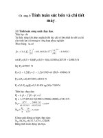
General
Solenoids
Relay as an example of a solenoid
In 1819, the Danish philosopher and physicist Christian
Oersted (1777 – 1851) discovered that a compass needle
is deflected by an electric current flowing through a
conductor.
The discovery of the link between electricity and
magnetism encouraged scientists and researchers to
perform extensive experiments and investigations. One
of these scientists was André Marie Ampère (1775 –
1836).
During these investigations, it became clear that the
magnetism generated by electric current extends through
space and produces a force which can be converted into
motion and vice-versa.
If an electrical conductor (e.g. copper) is wound to form
a coil, the magnetic force depends on the number of
windings and the strength of the energizing current.
If iron is located in this force field, it is attracted. An
iron core located within the coil bundles the field lines,
amplifying the magnetic effect.
1
7
2
3
6
4
E60672
5
1
Yoke
2
Armature
3
Two-way contact
4
Normally closed contact (break contact)
5
Normally open contact (make contact)
6
Relay coil
7
Coil core
Testing and measurement
Electromagnetism is used in a variety of ways today,
e.g. in generators, transformers, relays, electric motors
and last but not least in solenoids.
All solenoids operate by means of a coil and can only
be tested to a limited extent using an ohmmeter.
Solenoids are used as actuators in motor vehicles, e.g.
as:
During a continuity test only a coil open circuit or a
short to ground can be detected. A resistance test is only
useful if the resistance value of the coil is known.
– coils in fuel injectors or luggage compartment release
mechanisms
– relays for operating circuit actuation
– solenoid valves for ABS (Anti-lock Brake System)
and automatic transmission
– magnetic clutches for air conditioning compressors
As a rule, the resistance value is low as only a relatively
high current can generate a strong magnetic field. A
short circuit between the windings is therefore difficult
to measure.
In many cases, correct operation can be checked using
the OSC (Output State Control) mode in the WDS/IDS
by activating the actuator.
If a test using the powerprobe is required in the test
procedures, the actuator can be activated directly using
external voltage via the powerprobe in order to check
correct operation.
Service Training (G522586)
7
Electric motors
General
Electric motor without housing
Lesson 1 – General Information
Their power can range from a few milliwatts to several
megawatts. They can run at different speeds.
All electric motors operate according to the same
principle.
– The armature, which is permanently attached to the
axle, is brought into a rotational motion by the
Lorentz force.
– The Lorenz force is the force acting upon conductors
through which current is flowing in a magnetic force
field.
E60666
Design and operation
The South Tyrolean Johann Kravogl (1823 – 1889) is
regarded as the inventor of the electric motor (in 1867).
Electric motor components
An electric motor is an electrical device which converts
electrical energy into mechanical work with the aid of
magnetic fields, by generating a force or a torque and
consequently a movement.
4
1
3
Electric motors in everyday use
Our contemporary technological world would be
unimaginable without the use of electric motors. Heavy
locomotives are driven by electrical motors, as are
kitchen appliances and miniature clockworks.
Electrical motors relieve human beings from physical
work, e.g. in industrial facilities and in the household.
Characteristics of electric motors
Electric motors are:
– economic, achieving efficiencies of up to 95 % (c.f.
petrol engines, max. 45 %)
– compact
– relatively low-noise
– easy to control and operate
– inexpensive
– virtually maintenance-free
8
2
E60667
1
Housing (stator)
2
Permanent magnets
3
Rotor (armature)
4
Housing cap with bearing and connections
Electric motors basically consist of a rotor (moving part)
and a stator (stationary part).
Generally, the stator comprises a housing with magnets.
The brushes and electrical connections are located in
the housing cap.
In brush motors (with armature coil), the stator usually
comprises one or several permanent magnet(s).
The rotor consists of the armature and an axle, which
are bearing-mounted in the housing cap. In electrical
engineering, the term "armature" refers to a moving
(G522586)
Service Training
Lesson 1 – General Information
component; it can rotate – as the armature in the
alternator or starter motor – or it can move back an forth
like the armature in a solenoid.
Electric motors
Housing cap with bearing and connections
1
Rotor with armature coil
2
1
2
3
4
5
4
3
E60670
1
Connection between brushes and power supply
2
Spring
3
Thermoswitch (overload protection)
4
Brushes
E60669
1
Axle
2
Copper coil
3
Iron armature
4
Connection between copper coil and commutator
5
Commutator
The armature can consist of a permanent magnet or of
an armature on which a current-carrying copper coil is
wound.
So-called brushes (usually made from graphite) are used
to transfer the power via the connections (commutator)
of the moving armature.
The brushes are pressed against the commutator by
means of a spring.
If the rotor is a permanent magnet, no brushes are
required (brushless motor).
In brushless motors, the stator consists of magnetic coils
which create magnetic fields around the rotor.
The rotational activation of the magnetic coils is
performed by a controller.
In the event of excessive power consumption, e.g. due
to blocking, bi-metal switches (thermoswitches) are
used for overload protection. These interrupt the circuit
to the electric motor and the contact is only closed again
once the motor has cooled down.
Motor versions
Numerous motor versions are available. They are named
in accordance with their operating principle or the
relevant application. In contemporary motor vehicles,
actuator motors are primarily used, which are usually
designed as DC motors or stepper motors.
Service Training (G522586)
9
Electric motors
Lesson 1 – General Information
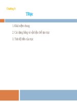
Actuator motor
1
What is meant by the term actuator motor, is a motor
which operates a mechanism to adjust e.g. a flap or a
linkage in an angular or a longitudinal direction. This
is generally performed by means of an intermediate
mechanical gear unit.
The exact position of the drive motor can be monitored
and determined using a controller. This is performed
e.g. via speed monitoring/measurement or monitoring
of the power consumption (increased power
consumption at limit stop).
2
3
4
5
6
7
E60458
Design of a stepper motor
1
Upper stator core for upper coil assembly
Position feedback to the controller is performed via
position sensors or microswitches.
2
Upper coil assembly
3
Lower stator core for upper coil assembly
Examples of automotive actuator motor applications
are the actuation of window regulators with one-touch
up and down modes, window regulators/roof opening
panels with pinch protection, blend door actuation in
heaters and air conditioning systems.
4
Rotor (polarized)
5
Upper stator core for lower coil assembly
6
Lower coil assembly
7
Lower stator core for lower coil assembly
DC motor
The rotor of a DC motor has a so-called commutator
coil. The stator has two distinct poles.
In small motors, the poles consist of permanent magnets,
in larger motors, the poles are current-carrying coils.
Because no feedback is required for actuation of e.g.
the windshield wipers, blowers or simple electric
window regulators, these motors are often referred to
as control motors.
Stepper motor
Stepper motors are used for precise mechanical angular
positioning. These motors feature a rotor made from a
magnetic material (e.g. steel) with non-magnetized
poles.
10
The stator consists of a large number of pole pairs and
energized windings. The stator is designed in a claw
pole configuration with two or four ring coils.
Each of the coil assembly is surrounded by a stator core,
which is divided into two parts – the lower and upper
stator core.
Each stator core features numerous teeth. These teeth
are all offset to one another and are arranged so that
they project in the direction of the rotor.
The controller cycles the current from one stator pole
to the other, deflecting the rotor poles. A torque is
generated.
If, for instance, four stator cores are installed each with
12 teeth, this means that a total of 48 teeth are available
as opposite magnetic poles.
As a result, 48 steps per revolution are achieved.
(G522586)
Service Training
Lesson 1 – General Information
Electric motors
Testing and measurement
Motors can only be tested to a limited extent using a
multimeter.
During a continuity test only a coil open circuit or a
short to ground can be detected. A resistance test is only
useful if the resistance value of the coil is known.
As a rule, the resistance value is low as only a relatively
high current can generate a strong magnetic field. A
short circuit between the windings is therefore difficult
to measure.
In many cases, correct operation can be checked using
the OSC mode in the WDS/IDS by activating the
actuator.
If a test using the powerprobe is specified in the test
procedures, the actuator can be activated directly using
external voltage via the powerprobe, in order to check
correct operation.
In some systems the relevant actuator is deactivated
following several subsequent activations within a
specified time in order to prevent overheating of the
motors. This should be taken into account during testing.
Service Training (G522586)
11
Piezoelectricity
Lesson 1 – General Information
The piezo-electric effect
A
B
C
1
4
2
5
1
4
3
6
E53584
A
Quartz crystal in rest state
3
Voltage generation
B
Action of an external force
4
Direction of force
C
Application of an electrical voltage
5
Deformation of crystal
1
Pressure
6
Voltage source
2
Ion displacement
F
Force
Piezo-technology finds application in optics, precision
mechanics, medicine, biology, consumer goods (e.g.
loudspeaker tweeters, quartz alarm clock beepers, etc.),
in mechanical engineering and the automotive industry.
Examples from the automotive industry include knock
sensors, pressure sensors, ultrasonic sensors,
acceleration sensors and actuators for opening fuel
injectors (on certain diesel engines).
The piezo-electric effect of natural crystals was
discovered in 1880 by the brothers Pierre and Jacques
Curie. The term piezo is derived from the Greek word
piezein, meaning to "press".
Outwardly, the quartz crystal is electrically neutral in
its rest state, i.e. the positively and negatively charged
atoms (ions) are in balance (A).
External pressure exerted on a quartz crystal causes the
crystal's lattice to deform. This results in ion
displacement. This causes a voltage to be generated (B).
If in the reverse case, voltage is applied, this leads to
deformation of the crystal and consequently to a force
(C).
The piezo-electric effect can best be illustrated by means
of a quartz crystal, on which pressure is exerted.
12
(G522586)
Service Training
Lesson 1 – General Information
Uses of piezo-electricity in practice
Piezoelectricity
The direct piezo effect is primarily utilized in sensors.
As sensors, piezo-ceramics convert a force acting upon
them into an electrical signal when the ceramic material
is compressed against its high rigidity.
A
Owing to the electrical displacement (dielectric =
electrical non-conductor) surface charges are generated
and an electric field builds up.
This field can be picked off as a (measurable) electrical
voltage via electrodes.
1
2
3
Summary: In the case of sensors, mechanical energy
is converted into electrical energy by means of a force
acting on a piezo-electric body.
B
Example application:
– Knock sensor
The indirect piezo effect is primarily used in actuators.
In the case of actuators, electrical voltage is converted
into mechanical deformation of a solid body, i.e. a
voltage acts upon a piezo-electric body, deforming it.
5
4
6
7
E53585
A
Direct piezo effect (sensors)
B
Indirect piezo effect (actuators)
1
Solid body in rest state
2
Force acting upon solid body (pressure)
3
Force acting upon solid body (tension)
4
Mechanical deformation of the solid body
5
Elastic tension
6
Force exerted
7
Example application: Fuel injector
Today's technologies use high-performance
piezo-ceramic materials instead of quartz crystals. When
it comes to applications, a distinction is made between
direct and indirect piezo effects.
Service Training (G522586)
If the body is prevented from deforming, elastic tension
is generated. Consequently, a force is exerted on the
structure preventing deformation of the piezo-electric
body.
Summary: In the case of actuators, voltage is applied
to the piezo-electric body, converting electrical into
mechanical energy.
Example application:
– Fuel injector for the Siemens common-rail system.
Testing and measurement
Testing and measurement are described for the
individual actuators.
13
Pyrotechnics
General
Lesson 1 – General Information
Air bag igniter
Pyrotechnics, as used in automotive applications has
nothing to do with fireworks. Pyrotechnic devices are
very small assemblies which can release high forces in
a precisely controlled manner even after many years of
maintenance-free installation, completely independently
of any power supply.
One example is the airbag. It must be triggerable over
the entire service life of a car, without any maintenance.
The force released must be very powerful, but precisely
controlled in order to block the driver's body without
e.g. throwing him or her back.
4
2
3
1
TIV4003002
1
Igniter
2
Propellant
Finally, the airbag must be autonomous as a reliable
3
Catalyst
power source is no longer available in a crashed vehicle.
4
Hybrid passenger air bag gas cartridge
Pyrotechnic applications in motor vehicles include:
– Safety belt pretensioners
The air bag inflator consists of the following main
components:
– Propellant cylinders for lateral seat shifting in the
event of a side impact
– Housing
– Pyrocutter for disconnecting the battery following a
crash
– Propellant
Further industrial applications include:
– Power cutters (e.g. for millimeter-precise cutting of
steel)
– Emergency elevator brakes or smoke doors
– Sprinkler systems
– High-performance aerosol generators
– Needleless injection systems
Design and operation
The design and operation of a pyrotechnic actuator is
described below based on the example of an air bag.
All air bag units consist of an igniter which inflates an
air bag.
Systems using an air bag inflator or a pre-filled gas
cartridge are used as igniters.
14
– Igniter
– Catalyst
The housing is made of high-strength steel. It contains
the propellant and the igniter, and features several
calibrated bores.
A heating wire (bridge igniter) and an ignition pellet
are located at the centre of the combustion chamber.
The pellet contains a small amount of gun powder.
The ignition current (min. 800 mA) flows from an
ignition capacitor via a heating wire in the bridge igniter.
The heat produced is sufficient to ignite the black
powder.
Depending on the manufacturer and application, the
resistance of the heating wire is between approx. 2 and
4 Ohms.
In air bags with a gas cartridge, the sealing cap of the
pressurized gas cartridge is ruptured by the igniter. The
gas then escapes, inflating the air bag.
(G522586)
Service Training
Lesson 1 – General Information
In air bags with air bag inflators, the propellant is ignited
by means of the igniter, generating the gas volume
required for filling the air bag.
No explosion occurs, the propellant burns in a controlled
manner and the expansion of the generated gas is
utilised.
The type of propellant depends very largely on the size
of the airbag and the required deployment speed.
1
Pyrotechnics
Safety
For a theoretical worst case scenario, the air bag inflator
is equipped with a so-called "fail-safe" device. If the
pressure in the combustion chamber exceeds a specified
maximum value, which is significantly higher than the
maximum operating pressure, the base of the combustion
chamber opens and the gas escapes without endangering
the driver/passenger.
In vehicles which are beyond repair the airbag must be
made unusable by enforced triggering before the vehicle
is scrapped. In this case, special safety measures which
are described in detail in the workshop literature must
be observed.
Safety information regarding the storage of airbag
components must also be observed.
2
TIE41393
Ignition unit
1
Ignition pellet
2
Boosting charge
A temperature of approx. 600 – 800 °C occurs in the
combustion chamber as a result of the chemical
combustion. The gas flows through a coarse screen into
the filter unit at a pressure of 120 bar. Here, the gas is
rapidly cooled down to below 80 °C, in order to virtually
exclude the risk of injury to the vehicle occupants.
The noise generated is approx. 130 dB (A). However,
because of the short duration of approx. 3 milliseconds,
damage to hearing is unlikely.
Driver and passenger air bags can be designed as dual
stage air bags. In this case, approx 70 % of the air bag
volume is deployed in the first stage, and the remaining
30 % in the second stage.
All air bags are provided with a sticker bearing a
barcode, article code and serial number. This allows the
unit to be traced throughout its entire service life
(production and installation dates).
Testing and measurement
WARNING: No resistance measurements must
be performed in the vicinity of the igniters of
pyrotechnic actuators. The safety instructions
contained in the current service literature must
always be observed when working on
pyrotechnic actuators.
Pyrotechnic actuators cannot be tested in the workshop.
It is only possible to check the wiring and mechanical
operation of the – SRS (Supplemental Restraint System)
module.
Air bag deployment lasts between 10 and 150
milliseconds.
Service Training (G522586)
15
OSC mode
Lesson 1 – General Information
General
"Activate control position" icon
In OSC mode (WDS/IDS datalogger) it is possible to
simulate various vehicle module output signals and
thereby directly activate actuators.
– Actuation of the previously selected output signal is
enabled using this icon. If an exclamation mark "!"
appears upon activation of this icon, the module
output signal cannot be overwritten and the actuator
can therefore not be activated.
The principle advantage of testing an actuator using this
function is that providing the OSC mode is operating
correctly, faults between modules and actuators can be
virtually excluded.
The plus icon (+)
– switches on the output signal. In the case of analogue
output signals, the control variable is increased.
The minus icon (–)
1
2
– switches off the output signal. In the case of analog
output signals, the control variable is decreased.
3
Delete icon
4
– Signal overwriting is reset and the actuator
deactivated using this icon.
5
When quitting OSC mode, all the overwritten output
signals are automatically reset.
Notes on OSC mode
E44009
1
OSC mode icon
2
"Activate control position" icon
3
Plus icon
4
Minus icon
5
Delete icon
The output signals which can be actuated by the user
are marked with a hash symbol (#) in the signal
selection.
When activating an actuator with the aid of OSC mode,
it must be ensured that the duration of activation
corresponds to the relevant use.
For instance, activation of the windshield washer pump
for more than 30 seconds may lead to destruction of the
pump.
For further information on OSC mode, please refer to
Student Information WDS, CG 8156/S, TC1012010S
or IDS, CG 8231/S, TC1011020H.
After selecting the signal (signal displayed with black
border), further icons appear in the vertical menu bar:
16
(G522586)
Service Training
Lesson 1 – General Information
Test questions
Tick the correct answer or fill in the gaps.
1. A comparison between setpoint values and actual measurement values takes place:
a. exclusively during transmission control.
b. exclusively during engine control.
c. during closed-loop control.
d. during open-loop control.
2. What are PWM signals?
a. Sinusoidal signals of a constant frequency.
b. Square-wave signals of a variable frequency.
c. Square-wave signals of a constant frequency.
d. Temperature-dependent DC voltage signals.
3. In electric motors, the rotating part is referred to as a ......................... and the stationary part as a
.............................. .
4. Electric motors are best tested using a multimeter.
a. True
b. False
5. When testing a solenoid
a. a high resistance value should be measured.
b. a low resistance value should be measured.
c. a continuity test is sufficient.
d. it should be noted that a test using the WDS/IDS is always possible.
6. When testing pyrotechnic actuators, the resistance of the heating wire should first be checked using a
multimeter.
a. True
b. False
Service Training (G522587)
17
Exhaust gas recirculation (EGR)
valves
Actuator motor-controlled EGR valve
(DC motor)
Lesson 2 – Actuators
Operating range
Value
Supply voltage
(actuator motor)
Approx. 12 V
Reference voltage
(position sensor)
Approx. 5 V
Signal type / voltage
(actuator motor)
PWM signal
E60555
Signal type / voltage
(position sensor)
DC voltage:
0.5 – 4.5 V
Examples of actuator motor-controlled EGR valves
Resistance (actuator motor)
1
2
1
1.6L Duratorq TDCi (DV) diesel
2
2.0L Duratorq TDCi (DW) diesel
Approx. 3 – 6 Ohms
Frequency
–
Testing options
Installation position
Diagnostic tool
Compatibility
In the exhaust tract, near the exhaust manifold
WDS/IDS DTC
Yes
(Diagnostic Trouble Code)
Physical operating principle
DC motor (actuator)
Guided diagnostics (WDS/ +
IDS)
Sliding-contact (position sensor)
DMM
++
Datalogger
++
Task / function
OSC mode #
++
The actuator motor opens or closes the EGR valve
according to the required recirculated exhaust gas
quantity.
Oscilloscope (breakout
box and adapter cable
required)
+
The actuator motor is activated by PWM signals.
Powerprobe
––
The duty cycle determines the aperture cross-section of
the EGR valve.
++ very suitable, + suitable
- unsuitable, - - very unsuitable
The position sensor integrated in the actuator motor
housing detects the current position of the EGR valve.
The more the EGR valve is opened, the higher the
resistance of the sensor.
18
(G522588)
Service Training
Lesson 2 – Actuators
Signal trace for correctly operating EGR valve after the
Exhaust gas recirculation (EGR)
valves
Special features
engine is switched off.
Following installation of a new actuator
motor-controlled EGR valve, a parameter reset of the
EGR valve must be performed using WDS/IDS.
E60554
In some versions, the EGR valve can be tested easily
and reliably using the WDS/IDS datalogger.
Example test on 2.0L Duratorq TDCi (DW) diesel
engine:
– Call up PIDs EGRDC (actuator motor duty cycle)
and DPFEGR (position sensor voltage characteristic).
– When switching off the engine a cleaning/adaptation
cycle is started, which opens and closes the EGR
valve six times.
– The position sensor in the operates in a voltage range
of approx.:
– 1 V (closed EGR valve) to
– 4.2 V (fully open EGR valve).
– In this manner, EGR valve faults can be located via
the datalogger display.
OSC mode test method
– Select the relevant PID in the WDS/IDS datalogger.
– Call up and activate OSC mode.
– Press the "+" key several times (the EGR valve is
opened progressively in steps); the engine should
run increasingly roughly (the engine may stall).
– If this is the case, the actuator motor is operating
correctly.
Service Training (G522588)
19
Lesson 2 – Actuators
Actuator motor-controlled EGR valve
(stepper motor)
Operating range
Value
Supply voltage
11 – 14 V
see table
Signal type / voltage
Pulse signals
Resistance
see table
Frequency
–
Coil supply voltage
E60927
Supply voltage between
Voltage (Volts)
PIN 2 (coil assembly A)
and ground
11 – 14
On the cylinder head
PIN 5 (coil assembly B)
and ground
11 – 14
Operating principle
Stepper motor coil resistance values
Installation position
Coil
between
Resistance
(Ohms)
A1
PIN 1 and 2
5 – 13
A2
PIN 3 and 2
5 – 13
B1
PIN 4 and 5
5 – 13
B2
PIN 6 and 5
5 – 13
Stepper motor
Task / function
The stepper motor opens and closes the EGR valve via
an actuating spindle.
The stepper motor comprises two coil assemblies (coil
assembly A and B) and a rotor. The coil assemblies are
sub-divided into coil sections A1/A2 and B1/B2.
Depending on the number of pulse signals, the EGR
valve is opened to a smaller or greater extent by the
stepper motor.
Testing options
Diagnostic tool
WDS/IDS DTC
Compatibility
Yes
Guided diagnostics (WDS/ +
IDS)
20
DMM
++
Datalogger
+
(G522588)
Service Training
Lesson 2 – Actuators
Diagnostic tool
Compatibility
OSC mode #
++
Oscilloscope (breakout
box and adapter cable
required)
––
Powerprobe
––
++ very suitable, + suitable
- unsuitable, - - very unsuitable
OSC mode test method
– Select the relevant PID in the WDS/IDS datalogger.
– Call up and activate OSC mode.
– Press the "+" key several times (the EGR valve is
opened progressively in steps); the engine should
run increasingly roughly (the engine may stall).
– If this is the case, the stepper motor is operating
correctly.
Service Training (G522588)
21
Lesson 2 – Actuators
EGR valve (vacuum-controlled)
Operating range
The table applies to the position sensor
Value
E47849
Installation position
Reference voltage
Approx. 5 V
Signal type / voltage
DC voltage:
0.5 – 4.5 V
Resistance
Approx. 1 kOhm
(valve closed)
Approx. 5 kOhms
(valve open)
Frequency
–
Testing options
Diagnostic tool
WDS/IDS DTC
Compatibility
Yes
In the feed line from the exhaust tract to the intake tract.
Guided diagnostics (WDS/ +
IDS)
Operating principle
Vacuum-controlled valve (actuator)
Sliding-contact potentiometer (position sensor)
Task / function
The vacuum-controlled EGR valve operates purely
mechanically and is therefore not subject to any
electrical testing.
The position sensor measures the current position of
the EGR valve.
The more the EGR valve is opened, the higher the
resistance of the sensor.
22
DMM
++
Datalogger
+
OSC mode #
––
Oscilloscope (breakout
box and adapter cable
required)
–
Powerprobe
––
++ very suitable, + suitable
- unsuitable, - - very unsuitable
In the 2.0L Duratorq TDCi (Puma) emission standard
IV diesel engine, the position of the EGR valve is
indicated in millimeters (mm) in the WDS datalogger.
(G522588)
Service Training
Lesson 2 – Actuators
Operation of the EGR valve and of the position sensor
can be tested as follows using the vacuum pump:
– Disconnect the vacuum hose from the EGR valve.
– Connect the vacuum pump to the vacuum hose of
the EGR valve.
– Turn ignition 'ON'.
– Operate the vacuum pump several times until the
EGR valve is fully open.
– The value indicated in the datalogger should increase
from 0 to 9 mm.
– During pressure equalization, the indicated value
should fall back to 0 mm.
Service Training (G522588)
23