Numerical Methods in Soil Mechanics 27.PDF
Bạn đang xem bản rút gọn của tài liệu. Xem và tải ngay bản đầy đủ của tài liệu tại đây (237.08 KB, 15 trang )
Anderson, Loren Runar et al "RISERS "
Structural Mechanics of Buried Pipes
Boca Raton: CRC Press LLC,2000
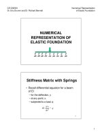
Figure 27-1 Notation for risers, showing radial pressure on the left side and shearing stress (drag-down) on
the right side that is caused by soil compression.
©2000 CRC Press LLC
CHAPTER 27 RISERS
Risers are basically pipes that are buried vertically,
or nearly so. In fact, some risers are inclined. They
are called risers because they usually "rise" from a
buried tank or pipe. Risers serve many purposes:
access (such as manholes and mine shafts),
cleanout, ventilation, collection of gas (methane from
sanitary landfills), standpipes (for water pressure
control), bins (for feeding underground conveyors),
accumulators (to collect entrapped air in water
pipes), etc. Most risers are cylinders (usually pipes).
See Figure 27-1.
Basic concerns are ring
compression and longitudinal (vertical) thrust. The
critical location of both is usually at, or near, the
bottom of the riser.
Ring Compression
From Chapter 6, ring compression stress is,
fc = rs x /t
where
fc =
sx =
r =
t =
circumferential stress in thin-wall riser,
external radial pressure against riser,
outside radius of curvature of the riser,
wall thickness of the riser.
For design, fc must be less than the yield stress of
the riser. The safety factor is needed because
pressure, sx, is sensitive to soil properties and to soil
placement, which never assures uniform pressure.
Because of soil arching action, sx is neither active
soil pressure, nor radial elastic stress. These are
limits only. At the lower limit, if a vertical hole were
bored into the ground, and the riser carefully slipped
down into it, sx would be zero down to some depth
below which the free-standing hole collapses (cavein) under the soil weight. Above this collapse depth,
the only pressure on the riser is hydrostatic pressure
if a water table is above the collapse depth. In such
a case, stability analysis applies as discussed in
Chapter 10. The "vacuum" in the pipe is external
hydrostatic pressure. The question, of course, is
©2000 CRC Press LLC
critical depth of the free-standing bored hole. The
surest procedure is a test hole.
At upper limit, if the soil is cohesionless, the riser
feels radial active pressure,
s = Ks z
where
sx =
K =
j =
sz =
radial pressure on the riser at depth z,
(1+sinj)/(1-sinj) from Mohr circle,
soil friction angle,
equivalent vertical stress caused by
compaction of the soil.
Active pressure is assumed if the soil is loose and
slides into place against the riser. If the soil is
compacted, sz is roughly equivalent to the
precompression stress at reversal of curvature of
the stress-strain diagram for the compacted soil.
See Figure 27-2. This analysis is upper limit
because arching action (sx) of the soil around the
pipe is ignored. In fact, arching action is significant.
The designer can get a feel for the effect of arching
action by an elastic analysis.
Elastic theory provides a conservative stress
analysis. Radial pressure against the riser at depth,
z, is sx. Principal stresses on an infinitesimal cube
of soil are shown in Figure 27-3. From elastic
theory, strains are:
Ee z = s z - n(s x + s y)
Ee y = s y - n(s x + s z)
Ee x = s x - n(s y + s z)
where:
E =
n =
e =
s =
modulus of elasticity,
Poisson ratio,
strains in the directions indicated,
principal stresses on the infinitesimal soil
cube in the directions indicated.
It is reasonable to assume that horizontal strains, e x
and e y, are zero because the soil is confined
Figure 27-2 Sketch of stress-strain diagrams for soil, showing precompression stresses located where
curvature reverses. Precompression stresses are approximately equivalent to the effect of compaction (soil
density). With no compaction (70% density?) curvature does not reverse.
Figure 27-3 Infinitesimal soil cube at the riser
surface, showing the principal stresses. sz is the
vertic al soil stress. sx is the radial soil pressure on
the riser. sy is the circumferential stress which
develops soil arching action.
©2000 CRC Press LLC
Figure 27-4 Horizontal stress, s x , is equal to the
bearing capacity of the soil that resists horizontal
movement of the riser into the soil. This is the
maximum stress that develops when the riser
deflects laterally into the soil.
horizontally. Therefore, sy = s x.
pressure against the riser,
sx = nsz /(1-n)
Solving for
. . . . . (27.1)
According to elastic theory, pressure on the riser is
sensitive to Poisson ratio, <, as follows:
n
0.00
0.1
0.2
0.3
0.33
0.4
0.5
sx
0
0.11sz
0.25sz
0.43sz
0.50sz
0.67sz
1.00sz
Applied to:
cork, trash.
Assume 0.5sz for waste.
for some plastics.
constant volume elastics.
The radial stress, sx, varies from zero to sz. Some
designers use the elastic model with a Poisson ratio
of 0.33, for which radial pressure on the riser is sx
= sz/2. But this rationale applies only to elastic
material. Soil is not elastic. Based on active soil
pressure against the riser,
sx = s z(1-sinj)/(1+sinj)
If soil friction angle is j = 30o, s x = sz/3. Although
conservative, the coefficient, 1/3, is more reasonable
than the 1/2 used by some designers.
If the riser deflects laterally, movement of the riser
causes passive soil resistance. From Chapter 4, at
passive soil resistance,
sx = s z (1+sinj)/(1-sinj)
If soil friction angle is j = 30o, s x = 3sz.
This is analyzed as pressure on one side of the riser.
See Figure 27-4. The only reaction to this force is
cantilever action which may be more critical than
ring compression if the riser can deflect laterally.
Design is classical analysis for a vertical cantilever.
It may be necessary to locate points of
counterflexure in the deflected riser.
©2000 CRC Press LLC
Thrust
Thrust is the vertical force on the riser. It is caused
by the frictional "drag-down" as the soil compresses.
Thrust depends upon: pressure against the riser, the
coefficient of friction of the soil on riser, and the
relative movement (compression) of the soil with
respect to the riser. A safety factor is required.
Analysis of the drag-down force is similar to the
analysis of silos in Chapter 22. The following design
procedure is conservative because soil arching
around the riser is neglected in calculating dragdown. In the following it is assumed that soil is
cohesionless. Two soil conditions are analyzed,
without compaction and with compaction. It is
assumed that soil is confined horizontally such that
(radial) strains are zero. Therefore, sy = s x. This is
modeled by a confined compression test. See Figure
27-3. For design, vertical stress, Q/A, must be less
than the yield stress, fc , reduced by a safety factor.
Q/A = fc /(sf)
. . . . . (27.2)
Notation:
Q = total drag-down load on the riser,
A = cross-sectional area of the riser = 2prt,
fc = longitudinal yield stress in the riser,
fz = longitudinal (vertical) stress in the riser,
r = mean radius of the riser,
t = wall thickness of the riser,
sx = radial (active) soil pressure on the riser,
sz = vertical soil pressure at depth, z,
z = depth to soil cube (Figure 3),
K = ratio of sx /s z at soil slip,
= (1- sinj)/(1+sinj) for granular soil,
j = soil friction angle,
m = coefficient of friction, soil on riser,
sf = safety factor.
If the soil is cohesive, K must be modified. See
Chapter 4. The vertical stress, fz, in the riser at
depth, z, is an upper limit because horizontal arching
of the soil, sy, is ignored. Q is the total
drag-down force of the soil on the riser as soil
compresses. It is assumed that the riser is fixed in
length, and is supported on a base that does not
settle. See Figure 27-2. At depth, z, vertical stress
in the riser wall caused by drag-down is,
fz = Q/A = Kzms z /2t
UNCOMPACTED SOIL
. . . . . (27.3)
where
t = msx = vertical shearing stress on riser,
sx = Ksz = radial soil pressure on the riser,
Q = przt = przmK sz = drag-down force.
sz is the precompression stress for samples of the
compacted soil. It can be found from stress-strain
diagrams of laboratory compression tests on
compacted soil.
CAVEAT — Usually, compacted soil does not
compress with respect to the riser. Therefore,
shearing stresses, t , do not develop. The very
purpose of compaction is to prevent relative
settlement of soil with respect to the riser. The
above rationale applies to "unusual" cases of relative
movement.
Structural Analysis of the Pipe
During backfilling, soil "slides" into place against the
riser such that radial pressure in Equation 27.3 is
roughly active soil pressure; i.e., sx = Ks z
K = (1-sinj)/(1+sinj)
. . . . . (27.4)
Uncompacted soil
The active radial pressure is sx = Ks z where s z is
the vertical soil stress at depth z.
Example 1
Figure 27-1 shows a riser in uncompacted soil.
Therefore, the sx-diagram is a triangle to some
depth, z. What is the drag-down force, Qs due to
shearing stresses? The volume under the sxdiagram is simply the area under the triangle, zsx/2,
times the circumference of the riser, 2pr.
Therefore, Qs = mp rzsx.
Compacted soil
If cohesionless embedment is uniformly compacted
(in lifts), it is reasonable to assume that s z is the
equivalent precompression stress of compaction. If
soil is compacted throughout the entire height of the
riser, radial soil pressure on the riser is constant —
not zero to maximum from top-to-bottom.
Therefore, the 2 in the denominator of Equation 27-3
cancels, and,
fz = Kzms z /t
COMPACTED SOIL
©2000 CRC Press LLC
. . . . . (27.5)
Figure 27-1 (right) shows loads on the pipe ring due
to soil and riser. The ring can be analyzed by closed
form integration. See Appendix A. Such analyses
are conservative, however, because arching of the
soil is ignored, both longitudinal and circumferential.
Moment, thrust, and shear in the ring make possible
the stress analysis of the ring. Plastic analysis is
more relevant than elastic analysis.
Stress
concentrations at the intersection of riser and pipe
are critical.
Surface Live Loads
If a live surface load can pass over the riser, the
riser must support the entire load. If a concentrated
dual-wheel load is located at a point on the rim of
the riser, the riser can be analyzed as a short column
with both an axial load and a moment due to the
eccentricity of load from the neutral axis of the riser.
The maximum stress is usually at or near the top. It
must be less than yield stress reduced by a safety
factor. Localized buckling could reduce the critical
load, P. The maximum stress, from classical
mechanics, is the familiar,
fc = P/A + Mc/I = 3P/2prt, approximate. . . . . (27.6)
where
P = dual-wheel load,
A = 2prt = cross sectional area of the riser,
M = Pr = moment of force on the riser,
I/c = ptr3/r = ptr2.
simply tire pressure, 105 psi, for which sx = 35 psi =
K(105 psi).
If the live surface load is not on the riser, but is
located on soil adjacent to the riser, the problems are
vertical force on the riser, and non-uniform radial
pressures.
Ring Compression:
The ring compression pressure, sx, under the wheel
load may greater than the passive resistance of the
soil around the rim. The riser rim could invert.
Approximate analysis is possible, but is usually not
justified.
The effect of non-uniform radial stresses on the ring
can be analyzed, if necessary, by the Castigliano
equation. See Appendix A.
Thrust
If live loads are anticipated, either the riser must be
able to support the loads, or loads must be kept off
the riser. Manholes in roads support wheel loads.
It is common practice to place a collar around the
rim of the riser. See Figure 27-5. The collar is not
attached to the riser. Therefore, it bears on soil.
The collar usually rises above the surface like a curb
so wheel loads do not roll onto the riser. See Figure
27-5. The collar keeps the wheel load far enough
away from the riser that radial soil pressure is not
excessive. Vertical soil stress, sz, next to the riser
can be calculated using the Boussinesq procedure.
See Chapter 4. Radial stress is sx = Ksz. Radial
stress is reduced by increasing distance, R, from the
riser. See Figure 27-6.
Example 2
Assume that an HS-20 dual- wheel load is P = 16
kips with tire pressure of 105 psi is located at
distance, R, from the riser. The depth to the
infinitesimal soil cube is Z. Assume that the soil is
cohesionless with a soil friction angle of 30o for
which K = 1/3. Values from Boussinesq are plotted
in Figure 27-6. Clearly, sx is reduced dramatically
as R increases. Shown for comparison is a plot for
R = 0; i.e., the wheel is on soil at the edge of the
riser. Theoretically, sx approaches infinity on the
soil surface where Z = 0 because Boussinesq
assumes a point load. In fact, the dual-wheel load is
spread over an area. The maximum pressure is
©2000 CRC Press LLC
Drag-down shearing stress caused by the wheel
load is, t = msx.
See Figure 27-1. Again, the problem is evaluation of
radial stresses, sx; and, again, for cohesionless soil,
the major distinction is between uncompacted and
compacted soil; i.e., between active soil pressure,
Equation 27.3, and equivalent precompressed soil
pressure, Equation 27.5. The drag-down shearing
force is m times the volume under the s x-diagram;
i.e.,
Qs = m s xdA
. . . . . . . . (27.7)
See Figure 27-5. For a concentrated wheel load, P,
radial soil stress, sx, at depth Z varies with radii, R,
from the wheel load (P-axis) to the riser. Moreover,
sx is the radial component of the Boussinesq stress
at R and Z. The boundaries of the pressurized area
to be integrated depend upon ring stiffness. It is
reasonable to assume an area equal to Z times oneeighth of the circumference (45o arc). At each
depth, Z, radial stress, sx , is K times the vertical
stress, sz, and is assumed to be constant around the
45o arc at depth Z.
Example 3
A riser is buried in uncompacted soil. Roughly what
is the drag-down force, Qs, due to the wheel load P
= 16 kips at R = 10 inches from the edge of the
riser? Radius of the riser is r = 16 inches.
From Figure 27-6 by counting squares, the area
under the (R=10) curve is roughly 100 lb/in. A 45o
arc of the riser is pr/4 = 12.5 inches. The stress
volume is approximately (12.5 in)(100 lb/in) = 1.25
kips. The shearing drag-down force is 1.25(m) kips.
If the coefficient of friction is m =
Figure 27-5 Collar for preventing excessive soil pressures on the riser due to surface wheel loads, showing
principal stresses on an infinitesimal soil cube at the riser surface and at depth, Z.
Figure 27-6 Radial pressures, sx, acting on the riser, as a function of depth, Z, and distance, R, from a 16kip wheel load to the riser.
©2000 CRC Press LLC
0.5, the drag-down force is Qs = 625 lbs. If R is
decreased to 5 inches, the area under the sx-curve
is roughly 2.5 times as large. The down-drag force
is (2.5)(625 lbs) = 1.56 kips, a quarter of the wheel
load. Keep wheel loads away from the edge of the
riser.
Risers in Sanitary Landfills
Sanitary landfills pose unique problems because of
compressibility of waste material. Properties of the
waste vary. Unit weight of waste is typically g = 75
pcf. Some engineers design for 80 pcf to include
variable water content and non-homogeneity.
Vertical compression can be as much as 30%.
Temperature can vary from below freezing to 120o
F. Landfills spread horizontally as the height rises.
The rise is gradual (over many years). Design of
risers must take into account lateral deflection due to
spreading of the sanitary landfill, and drag-down
(friction as the waste compresses).
Drag-down
For lack of accurate values, the drag-down
"coefficient" is sometimes set at 0.5; i.e., half the
vertical pressure of the waste at any given depth.
The result is a triangular drag-down shear diagram
(t -diagram) as shown on the right side of the riser in
Figure 27-1 where t is 0.5(s z), and where s z = g z.
Because sanitary landfills are usually high, z can be
a large value. To relieve the riser of large dragdown thrust, and to protect the riser, a "chimney" of
compacted, select backfill is sometimes specified
with the riser serving as the "flue." An alternative
could be a telescoping riser. See Figure 27-7. It
may be prudent to provide flanges on each stick of
pipe. Analysis shows that friction should hold the
sticks in place. However, variations in temperature
cause the sticks to lengthen and shorten, both of
which cause incremental creep downward. Flanges
resist downward creep. Flanges can be placed
anywhere on the larger diameter telescoping sticks.
Some designers use pipes with the bell on one end to
serve as a flange for the larger diameter sticks.
Flanges on the smaller diameter sticks must be far
©2000 CRC Press LLC
enough from the ends to allow telescoping by
insertion of the smaller diameter pipe into the larger
diameter pipe.
The required bearing area of the flanges can be
analyzed as follows. Area times bearing capacity of
the soil (trash) must exceed the frictional drag-down
plus the weight of each stick. This design procedure
is conservative because downward creep and
telescoping both reduce or eliminate drag-down.
Safety factors are not needed.
Resistance to Live Loads
When a live load passes over a riser supported by a
buried pipe or tank, the question arises as to how
much of the load is felt. If the riser is noncompressible (no slip joints or corrugated sections),
the entire live load could be supported by the pipe or
tank. If the riser is compressible, it shortens under
the live load. The load, or part of the load, is
supported by frictional resistance of the waste. That
frictional resistance is analyzed the same way as
drag-down, except that it is reversed in direction.
Lateral Deflection
If insertion clearance is not adequate between the
larger and smaller sticks, lateral deflection of the
riser may bind contiguous sticks. At worst, the
bending moment could fracture the ends. Lateral
deflection can be accommodated by shortening the
lengths of the sticks and the insertions, and by
increasing the annular space between the smaller
and larger diameter sticks. Gaskets at the insertions
may or may not be required to prevent influx of
leachate or soil. The length of the sticks may be
determined by the rate of rise of the sanitary landfill.
Telescoping sticks facilitate rise, but the stick added
for each lift must be limited in length depending on
the method of support. A mound of select granular
soil around the base of the added stick may
adequately support short sticks. Otherwise, tie
wires are needed.
Foundation for the Riser
In some cases, the weight of the riser and the drag-
Figure 27-7 Diagrammatic sketch of a telescoping
riser to accommodate compression of the waste in
sanitary landfills, shown here with flanges to resist
incremental creep downward. The flanges do not
necessarily have to be at midlength of the sticks.
©2000 CRC Press LLC
down force are supported by a foundation that
straddles the pipe or tank. This is typical of heavyduty risers such as shafts through which ore or
aggregate is dropped onto a conveyor belt or skip.
In addition to drag-down, both inside and outside the
riser, vibrator motors are attached to the riser to
keep the product flowing.
In many cases, the riser is supported directly on the
pipe or tank. See Figure 27-8, which shows a riser
through which crushed stone is dropped onto a
conveyor belt in a 120-inch-diameter corrugated
steel pipe. Views of the opening are shown from
inside the pipe. Pipe rings are cut by the opening.
Therefore, the ring compression which supports
external loads is lost. Thrust, Q, from the riser must
be supported by rings adjacent to those that are cut.
In the example of Figure 27-7, a collar of plates is
welded to the inside of the pipe. The collar is
equivalent to a boss around the hole where stresses
are concentrated.
The adjacent rings must
withstand their own ring compression plus the ring
compression of the cut rings. In some cases, a steel
frame outside the pipe replaces the rings that are
cut. If the riser thrust is supported on the pipe, it
may be prudent to analyze the ring by Castigliano's
equation or by finite element analysis.
tanq = (D'-D)/DL
q = 1.89o
Offset = 4.4 inches
in 11 ft pipe length.
Risers on Slopes
Following is a rational procedure for the structural
design of a riser (or any pipe) when buried on an
incline.
Notation and Assumed Data — Assumptions are
conservative. For the following examples, data are:
Soil:
Landfill trash —
g = 100 pcf = unit weight of landfill,(usually
closer to 75 pcf),
m = 1/4 = coefficient of friction of landfill on
pipe,
H = 100 ft = height of landfill cover over the
pipe,
P = g H = 10 ksf = vertical pressure on the pipe.
Select granular embedment soil —
g = 125 pcf = unit weight compacted,
j = 30o = embedment soil friction angle,
e = vertical soil compression at pressure P,
m = 1/3 = coefficient of friction of embedment
against pipe.
Example 4
A telescoping riser,
PVC SDR 26, stands
vertically in waste.
D = 18.000,
D' = 18.462,
DL = 14 inches,
wt = 24.5 lb/ft,
g = 80 pcf waste,
t = 0.5s x ,
L = 11 ft,
Df = flange diam.
Find:
Maximum angle offset,
allowed if the sanitary
landfill should spread.
©2000 CRC Press LLC
Pipes:
s
=
sf
=
F/D =
F/D =
D
=
ID
OD
E
t
I
=
=
=
=
=
stress,
yield stress (assumed to be failure),
pipe stiffness by parallel plate test,
53.77EI/D3 by analysis,
mean diameter of the pipe, (also used for
nominal diameter),
12 inches = inside diameter,
outside diameter = ID + 2t,
modulus of "elasticity",
wall thickness,
t3/12 = moment of inertia of the longitudinal
cross section of the pipe wall about its
neutral axis.
Assumed Data —
12D PVC Schedule 80, DR = 18.56
Figure 27-9 Buried pipe on a 1v:3h slope, showing the soil pressure against the elliptical pipe cross section cut
by a vertical plane. Because Px < P, the potential for soil slip is less than for a circular pipe.
Figure 27-10 Equivalent horizontal soil supports for embankment and trench conditions. In both cases, the
embedment is confined.
©2000 CRC Press LLC
sf
=
=
=
=
4000 psi (long-term tension),
7500 psi pristine,
E
370,000 psi,
OD
12.75,
ID
=
11.48,
D
= 12.11,
t
= 0.687,
d
= 7.5% allowable,
F/D = 300 psi (by analysis).
12D HDPE, SDR 11
sf
= 1600 psi (50-yr tension),
= 3200 psi pristine,
E
= 135,000 psi,
OD = 12.75,
ID
=
10.432,
D
= 11.59,
t
= 1.159,
F/D = 600 psi (by analysis).
1. Ring compression stress, s = P(OD)cosq/2t, must
be less than sf. See Figure 27-9. P is the vertical
soil pressure at the depth of the pipe. Because cosq
= 0.95 on the 1v:3h slope, it is close enough to unity
to ignore in the examples that follow. On a slope,
the vertical section is an ellipse for which the ratio of
horizontal to vertical radii is greater than 1.
Therefore, for stability, less soil support is required
on the sides of the ellipse than on the sides of the
circular pipe. A horizontal pipe is the worst case for
analysis.
2. Ring deflection, d = D/D , must be less than the
allowable d set by a specification (based on cracked
joints, accessibility of tools in the pipe, etc.) to less
than 7.5% in this example. Upper bounds for ring
deflection.
a) Ring deflection is no greater than vertical
compression, e , of the sidefill embedment. Values
for e are found by confined compression tests in a
soils laboratory. For typical select embedment
compacted to 90%, standard Proctor density is e <
3%. Therefore, in select, compacted embedment,
there is little concern for ring deflection. See Figure
27-10. Ring deflection that is assumed equal to soil
strain is conservatively high because the stiffness of
the ring is neglected.
b) Worst-case ring deflection due to assumed
vertical pressure, P, shown below, can be calculated,
by elastic analysis d = 0.56P/(F/D) . This theoretical
ring deflection is an upper bound because horizontal
soil support is neglected. Accordingly, upper bounds
for ring deflection are:
PVC,
d = 13%
HDPE, d = 6.5%
sketch here
Example 5
What are the safety factors for PVC and HDPE in
ring compression? Neglecting cosq = 0.95 (for
worst case cosq = 1), assume horizontal pipes. The
limit of ring compression stress is usually assumed
to be the allowable, sf, which is yield stress in
tension — always less than compression.
PVC,
s = 1300 psi. Safety factor is nearly 6.
HDPE, s = 760 psi. Safety factor is over 4.
What is the height of cover at yield stress in the pipe
wall?
PVC,
H = 580 ft.
HDPE, H = 420 ft.
©2000 CRC Press LLC
Suppose the pipes were heavier, say PVC Schedule
120 and HDPE, SDR 9,
PVC-120
d = 4%
HDPE-9
d = 2%
SOIL SUPPORT WOULD NOT BE NEEDED.
With horizontal soil support, heavier pipes are not
justified.
Horizontal soil support reduces ring
deflections. These theoretical ring deflections are
even more conservative because soil stiffness and
arching action of the soil are neglected.
3. Longitudinal slippage of the pipe down the slope
must be prevented. Slippage is caused by the
downhill component of the weight of the pipe and by
compression of the landfill over time. Shearing
forces of landfill on the pipe tend to drag the pipe
downhill. See Figure 27-9. Also longitudinal
expansion and contraction of the pipe, due to
changes in temperature and pressure, cause
incremental “creep” down the slope.
a) Downhill slippage is prevented by thrust restraints
such as thrust blocks, collars, and flanges,
that are secured to the slope. Until the slope is
retained by landfill, the slope must be less than the
angle of repose of the soil. For a granular soil slope,
the angle of repose is usually greater than 30o. The
slope at 1v:3h is 18.4o — less than 30o.
b) Downhill slippage is prevented by a good bedding
with a coefficient of friction of soil on pipe greater
than the coefficient of friction of landfill on pipe.
See Figure 27-9. Assuming the worst-case loading
of Example 5, the longitudinal friction force is
roughly, F = P(OD)m cosq. The only variable for
friction force of the landfill and friction force of the
bedding is m , which should be less for the landfill
than for the bedding. A good bedding in contact
with the pipe is required.
5. Conditions for conservatism and mitigation include
neglect of horizontal support of the pipe by the soil.
Such neglect may be justified for a rigid ring. For a
flexible ring, horizontal soil support reduces both
ring compression and ring deflection.
Soil arching protects pipes. See Figure 27-10.
Plastic Pipes:
a) Short-term yield strength is a pertinent, but
conservative, property of plastic pipes. Long-term
yield strength is not pertinent if the embedment holds
the ring in shape. The ring conforms with the soil
and stresses relax faster than the long-term strength
regresses. At constant deformation, if
©2000 CRC Press LLC
failure does not occur when full load is applied,
failure won't occur. But if stress suddenly increases
before the time to long-term strength regression, the
strength of plastic is still pristine.
b) If stresses are persistent, and the ring is not held
in shape by soil, the strength of the plastic regresses
over time. An example is a pipe buried in fluid at
constant pressure. A good soil embedment assures
constant deformation such that stress relaxation
prevails over strength regression.
c) The rate of loading in a sanitary landfill is
incremental and slow (years) — not sudden as
assumed in these examples. Slow loading allows
time for stress relaxation.
d) Yield stresses are usually reported for hoop
strength in TENSION, not COMPRESSION. Ring
compression strength is greater than the tension
yield stresses assumed in these analyses.
e) Ring analysis on a slope is less severe than
analysis on a horizontal plane.
Soil:
a) Vertical soil compression is pertinent in checking
the predicted upper bound of ring deflection.
b) Active and passive resistance of soil becomes
pertinent if the pipe ring is so flexible that ring
buckling becomes an issue. Such is not the case in
these examples. The pipes are not flexible enough.
c) Active and passive resistance of particulate soil
are functions of the soil friction angle, j ; i.e., K =
(1+sinj)/(1-sinj), where K is the ratio of orthogonal
principal normal stresses in the soil at soil slip.
Shearing planes form. Soil slip is not an issue for
these plastic pipes because ring deflection is small;
i.e., ring stiffness is substantial.
d) On a slope, the frictional drag-down force of
landfill on the pipe is usually less than the fric tional
resistance of the bedding because the coefficient of
friction on top is less.
PROBLEMS
27-1. Find the minimum Df in Example 4 required to
support a small pipe from creeping downward into a
large pipe. Bearing capacity of the waste is 800 psf.
Frictional resistance to creep is negligible.
(Df = 19.64)
27-2. What live load, W, can be supported on top of
the riser if the top 11-ft pipe is small with Df =
20, and if live load forces the pipe downward
reversing friction?
27-3. Suppose the first (bottom) riser pipe of
Example 4 is a small pipe 20 ft long, no flange,
embedded to the top in 20 ft of loose waste.
Estimate the bearing force on the base of this pipe.
Is the pipe weight significant?
(Q = prLg = 38 kips)
27-4. Derive Equations 27.1 and 27.3.
©2000 CRC Press LLC