Test-universe-advanced-differential-module-application-note-example-of-use-transformer-enu
Bạn đang xem bản rút gọn của tài liệu. Xem và tải ngay bản đầy đủ của tài liệu tại đây (1.7 MB, 43 trang )
Testing Transformer
Differential Protection
Practical Example of Use
Testing Transformer Differential Protection
Manual Version: Expl_TDiffProt.ENU.1 - Year 2013
© OMICRON electronics. All rights reserved.
This manual is a publication of OMICRON electronics GmbH.
All rights including translation reserved.
The product information, specifications, and technical data embodied in this manual represent the technical
status at the time of writing and are subject to change without prior notice.
We have done our best to ensure that the information given in this manual is useful, accurate, up-to-date and
reliable. However, OMICRON electronics does not assume responsibility for any inaccuracies which may be
present.
The user is responsible for every application that makes use of an OMICRON product.
OMICRON electronics translates this manual from the source language English into a number of other
languages. Any translation of this manual is done for local requirements, and in the event of a dispute between
the English and a non-English version, the English version of this manual shall govern.
2
Content
Preface ......................................................................................................................................................... 4
1
Application Example ............................................................................................................................ 5
2
Theoretical Introduction to Transformer Differential Protection ..................................................... 7
2.1 Protection Principle ........................................................................................................................ 7
2.2 Operating Characteristic ................................................................................................................ 8
2.3 Zero Sequence Elimination ......................................................................................................... 11
2.4 Transformer Inrush ...................................................................................................................... 13
3
Practical Introduction to Transformer Differential Protection Testing ......................................... 15
3.1 Defining the Test Object .............................................................................................................. 16
3.1.1
3.1.2
3.2
Global Hardware Configuration of the CMC Test Set ................................................................. 26
3.2.1
3.2.2
3.2.3
3.3
Example Output Configuration for Differential Protection Relays .................................................... 26
Analog Outputs ............................................................................................................................... 27
Binary Inputs ................................................................................................................................... 27
Local Hardware Configuration for Differential Protection Testing ............................................... 28
3.3.1
3.3.2
3.4
Device Settings ............................................................................................................................... 16
Defining the Differential Protection Parameters .............................................................................. 18
Analog Outputs ............................................................................................................................... 28
Binary Inputs ................................................................................................................................... 28
Defining the Test Configuration ................................................................................................... 29
3.4.1
3.4.2
3.4.3
3.4.4
3.4.5
3.4.6
General Approach ........................................................................................................................... 29
Configuration Test........................................................................................................................... 30
Operating Characteristic Test ......................................................................................................... 33
Trip Times Test ............................................................................................................................... 36
Inrush Blocking Test ....................................................................................................................... 39
Testing Three-Winding Transformer Differential Protection ............................................................ 42
Support....................................................................................................................................................... 43
Please use this note only in combination with the related product manual which contains several important safety
instructions. The user is responsible for every application that makes use of an OMICRON product.
© OMICRON 2013
Page 3 of 43
Preface
This paper describes how to test the transformer differential protection function. It contains an application
example which will be used throughout the paper. The theoretical background of transformer differential
protection will be explained. This paper also covers the definition of the necessary Test Object settings as
well as the Hardware Configuration for these tests. Finally the Advanced Differential test modules are used
to perform the tests which are needed for this protection function.
Supplements:
Sample Control Center file Example_AdvDifferential_Transformer.occ (referred to in this
document).
Requirements: Test Universe 2.41 or later; Advanced Differential and Control Center licenses.
Note:
© OMICRON 2013
The description of the Differential test module is not a part of this document.
Page 4 of 43
1
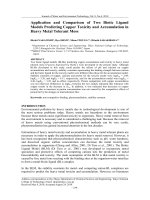
Application Example
220 kV
400/1
Protection functions
(87) Differential Protection
(50/51) Definite Time Overcurrent Protection
Transformer Differential Relay
600/1
110 kV
Figure 1: Feeder connection diagram of the application example
© OMICRON 2013
Page 5 of 43
Parameter Name
Parameter Value
Frequency
50 Hz
160 MVA
231 kV
Transformer data
115.5 kV
Notes
Rated power
Rated voltage, Side 1 (used for the calculation of the
transformation ratio of the transformer)
Rated voltage, Side 2 (used for the calculation of the
transformation ratio of the transformer)
Yyn0
Vector group
400 A / 1 A
CT ratio, Side 1
600 A / 1 A
CT ratio, Side 2
CT data
0.25 Iref
Differential characteristic
settings
6.0 Iref
0.3
Slope 1 of the differential characteristic
0.7
Slope 2 of the differential characteristic
4.0 Iref
Harmonic restraint
settings
Idiff>, Pick-up value of the differential protection (Iref is a
reference current which can be obtained from the relay
manual. In this case it is the rated current of the
transformer)
Idiff>>, Second element of the differential protection
(there is no stabilization above this value)
20% Idiff
Bias current where the first slope ends and the second
slope begins.
2nd harmonic restraint value (relative to the fundamental
frequency differential current)
Table 1: Relay parameters for this example
Note:
© OMICRON 2013
Testing of the Restricted Earth Fault protection function, Thermal Overload protection function,
etc. is not part of this document.
Page 6 of 43
2
2.1
Theoretical Introduction to Transformer Differential Protection
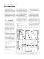
Protection Principle
The most important components in a power transmission and distribution system are the transformers, the
generators and the busbars. Usually differential relays are applied as their main protection against shortcircuit faults within the protected area.
The current differential principle is based on Kirchhoff’s law, i.e. the sum of the currents flowing into a
conducting network is zero.
I load side 1
I load side 2
Protected
Object
Side 1
1A
0°
1A
-120°
1A
120°
Side 2
1A
180°
1A
60°
1A
-60°
Ph A
Protected
Object
Ph B
Ph C
Protected Zone
Figure 2: Protection principle of the transformer differential protection
This principle applies to each phase separately. Therefore, the following equation can be calculated for each
phase.
n
I
i
I1 I 2
In 0
i 1
During a fault in the protected zone, a current will flow from one phase to another phase or to ground. In this
case the sum of the measured currents in at least one phase is not zero. Therefore, the relay can detect the
fault.
However, this is only valid if all CT ratios are the same and if the current is not transformed within the
protected object. The transformation ratio and the vector group of a transformer, as well as the CT ratios and
the positions of the CT star-points, will cause problems with the calculation of the current sums. Numerical
differential relays can calculate these effects and, therefore, compensate for their influence. For
electromechanical differential relays, interposing transformers have to be used instead.
Note:
© OMICRON 2013
The following parts of this document will only focus on transformer differential protection.
Page 7 of 43
2.2
Operating Characteristic
If the transformer is equipped with an on-load tap changer (OLTC), its transformation ratio varies over the
tapping range. This changes the ratio of the currents on side 1 and side 2 and thus produces a spill (out-ofbalance) current in the relay. Some other effects, such as the current transformer accuracy (including CT
saturation), the magnetization of the transformer, etc., also add to this spill current.
The magnitude of the spill current increases as the load on the transformer increases. The differential relay,
however, must not operate in this case. The corresponding solution and further sources for spill currents will
be dealt with in the following sections.
Idiff = ISide 1 - ISide 2
Sum
Current
Transformer
Tap changer /
Leakage
Magnetization
Iload
Figure 3: Natural error currents of the transformer
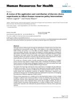
In Figure 3 it can be seen that the magnitude of the spill current (Sum) depends on the transformer load
current. To compensate for these error currents, the differential protection must be provided with a bias
element. This bias element depends on the current flowing through the transformer which, under normal
conditions, is the load current.
Note:
The calculation method of the bias current depends on the relay manufacturer (see Table 2).
Calculation Method
Manufacturer
Notes
ISide 1 ISide 2
AEG/ALSTOM/AREVA *), (K1 = 2), e.g. PQ7x, P6x
Various conventional (electromechanical) relays
*) = only valid for two-winding
transformers, for three-winding
transformers see below
SIEMENS (K1=1), e.g. 7UT5x/7UT6x
GEC (K1=1), e.g. series KBCH
SEL (k1=2), e.g. SEL5
AEG/ALSTOM/AREVA *), (K1 = 2)
*) = only valid for three-winding
transformers, for two-winding
transformers see above
I
Side 1
K1
ISide 2 / K1
min ISide 1 , ISide 2
max ISide 1 , ISide 2
ISide 1 ISide 2 cos
SEG/Woodward;
conventional (electromechanical) relays
Elin/VATECH, e.g. DRS
GE Multilin SR745
ABB
Table 2: Selection of different calculation methods for the bias current (depending on the relay manufacturers); The currents are scaled
to the nominal current of the transformer
© OMICRON 2013
Page 8 of 43
With this value the construction of an operating characteristic is possible.
Idiff
ID>>
Characteristic
Sum
Tripping
Blocking
Current
Transformer
Tap changer /
Leakage
ID>
Magnetization
Ibias
Figure 4: Operating characteristic of a transformer differential protection device
As shown in Figure 4, the operating characteristic has to cover the spill currents during normal conditions,
thus enabling the device to determine between blocking and operating. The design of the operating
characteristic (number of line segments, slope, etc.) differs widely between manufacturers and relay types.
For the following example, the AREVA P633 is used. Figure 5 and Figure 6 show the parameters and the
tripping characteristic of the P633.
Figure 5: Relay settings for the differential operating characteristic (AREVA P633)
Idiff
Idiff>>> = 6
(072.144)
0.7
(
6)
m=
2(
fixe
dv
alu
e)
=
m2
4
2.1
07
Idiff> = 0.25
(072.142)
07
0.3 (
m1 =
5)
2.14
IR,m2 = 4 (072.147)
Ibias
Figure 6: Operating Characteristic for the AREVA P633
© OMICRON 2013
Page 9 of 43
Figure 7 and Figure 8 show the settings and the operating characteristic of the Schweitzer SEL-387 for
comparison.
Figure 7: Relay settings for the operating characteristic (SEL-387)
Idiff
U87P = 6
=
P2
SL
1
SLP
70
%
%
= 30
O87P = 0.25
IRS1 = 4
Ibias
Figure 8: Operating characteristic for the SEL-387
© OMICRON 2013
Page 10 of 43
2.3
Zero Sequence Elimination
External phase-to-phase or three-phase faults cannot cause differential currents. This is not the case,
however, with external phase-to-ground faults at a winding with a grounded star-point.
I Side 2
I Side 1
2 Inom
I Side 1 1 Inom
1 Inom
IDiff I Side 1 I Side 2
I Side 2
3 Inom
0
0
2 Inom 3 Inom 1 Inom
1 Inom 0 1 Inom
1 Inom 0 1 Inom
Figure 9: Differential currents due to an external phase-to-earth fault
The fault current on the grounded side (side 2) will lead to a current in the faulty phase on the non-grounded
side (side 1) as shown in Figure 9. As the star-point of side 1 is not grounded, the current of the faulty phase
splits in to the non-faulty phases. The zero sequence current of side 2 will be compensated in the delta
winding. The fact that side 2 has a zero sequence current and side 1 does not have one causes a differential
current. This differential current, during external phase-to-ground faults, may lead to an unwanted operation
of the protection relay. Therefore, the zero-sequence must be eliminated from the currents seen by the relay.
Note:
The way the elimination is achieved differs between conventional and numerical relays. The
following discussion is only valid for numerical relays.
Zero-sequence current elimination methods for
numerical relays
Arithmetical
Via measurement
Side 1
Side 2
Internal correction of the currents
by means of mathematical models
Disadvantage: like
electromechanical relays with YdYinterposing current transformers the
sensitivity for phase-to-ground
faults is reduced by 1/3
Differential Relay
Figure 10: Methods of zero-sequence current elimination (numerical relay)
© OMICRON 2013
Page 11 of 43
Note:
This document only focuses on the arithmetical method. The activation logic of which depends
on the manufacturer. Figure 11 shows an example of these settings.
1
Figure 11: Relay settings for the activation of the arithmetical methods of Zero-sequence current elimination (AREVA P633)
1.
The arithmetical method of zero-sequence elimination is activated for side 2 (the 110-kV-side, see
Table 1)
Figure 12 shows the calculation of the zero sequence elimination with the fault currents from Figure 9.
Phase Currents:
2 Inom
I Side 1 1 Inom
1 Inom
I Side 2
3 Inom
0
0
Zero Sequence Elimination for Side 2:
I 0 Side 2
I
Side 2
1
1
I A I B I C 3 Inom 0 0 1 Inom
3
3
I Side 2 I 0 Side 2
3 Inom 1 Inom 2 Inom
0 1 Inom 1 Inom
0 1 Inom 1 Inom
Differential and Bias Currents after Zero Sequence Elimination:
IDiff I Side 1
IBias
I
Side 2
2 Inom 2 Inom 0
1 Inom 1 Inom 0
1 Inom 1 Inom 0
I Side 1 I Side 2
2
2 Inom 2 Inom 2 Inom
1
1 Inom 1 Inom 1 Inom
2
1 Inom 1 Inom 1 Inom
Figure 12: Arithmetical zero sequence elimination
With the arithmetic zero-sequence current elimination, there is an “error” based on the correction formula
which influences the bias currents displayed in the relay. Therefore, the relay will also measure bias currents
in the non-faulty phases. The same effect occurs when using interposing transformers.
© OMICRON 2013
Page 12 of 43
2.4
Transformer Inrush
Inrush is a phenomenon which commonly takes place directly after a transformer is energized, due to
saturation of its magnetic core. This saturation causes high power losses which lead to high currents. As
they only flow on one side of the transformer, the relay will interpret them as differential currents, which will
lead to an unwanted trip, if the relay is not stabilized against inrushes. The three phase currents during an
inrush are shown in Figure 13.
Figure 13: Transient record of a transformer inrush
This inrush current has a unique wave form which is characterized by a high percentage of even harmonics
– especially of the second and fourth harmonic. There are different ways of stabilizing a relay against inrush
currents, which use frequency analysis or time signal analysis. The most common methods are described in
the following section.
> Harmonic Blocking:
Whenever the percentage of the second harmonic current exceeds the
setting value, the relay will block as shown in Figure 14.
Idiff
Tripping
Blocking
ID>
Harmonic Blocking
Setting
I2. Harmonic
Figure 14: Harmonic blocking scheme
© OMICRON 2013
Page 13 of 43
> Harmonic Restraint:
The second and fourth harmonic currents will be added to the bias current.
Figure 15 shows that the increased bias current will prevent the relay from
tripping during inrushes.
Idiff
Tripping
Bias Current without
Harmonics
Bias Current with
Harmonics
ID>
Blocking
Ibias
Figure 15: Differential protection operating characteristic with harmonic restraint
> Wave form analysis:
Numerical time domain analysis of the transient current signal is used to
recognize wave shapes which are typical for transformer inrushes.
During the inrush, the magnitudes of the currents are different in each phase. In some phases the harmonic
currents may be just enough to block the relay whereas in the remaining phases it may be just insufficient
enough. These non-blocked phases will cause an unwanted operation. To prevent this unwanted operation
the relay can use cross-blocking. This function blocks the trip in all phases if one phase detects an inrush.
The AREVA P633 uses harmonic blocking to prevent unwanted operations during transformer inrush
occurrences. Its harmonic blocking characteristic is displayed in Figure 16. It shows that, in addition to the
characteristic in Figure 14, the blocking is stopped when the differential current exceeds the Idiff>> setting.
Idiff
Idiff>>
(072.142)
Tripping
Blocking
Idiff>
(072.143)
RushI(2f0)/I(f0)
(072.159)
I2. Harmonic
Figure 16: Inrush blocking characteristic of the AREVA P633
© OMICRON 2013
Page 14 of 43
3
Practical Introduction to Transformer Differential Protection
Testing
The Advanced Differential test modules are designed for testing any kind of three-phase current differential
protection functions, for assets such as transformers, motors, generators, busbars, lines and cables. These
test modules are:
>
>
>
>
The Diff Configuration module for testing the configuration of the differential protection which
consists of the wiring and the relay parameters such as transformer data, CT data and zero
sequence elimination.
The Diff Operating Characteristic module for testing the operating characteristic of the
differential protection.
The Diff Trip Time Characteristic module for testing the trip times of the differential protection.
The Diff Harmonic Restraint module for testing the blocking of the differential trip due to current
harmonics.
These test modules can be found on the Start Page of the OMICRON Test Universe. They can also be
inserted into an OCC File (Control Center document).
© OMICRON 2013
Page 15 of 43
3.1
Defining the Test Object
Before testing can begin, the settings of the relay to be tested must be defined. In order to do that, the
Test Object has to be opened by double clicking the Test Object in the OCC file or by clicking the
Test Object button in the test module.
3.1.1 Device Settings
General relay settings (for example, relay type, relay ID, substation details) are entered in the RIO function
Device. The CT data is not entered in this RIO function. It will be entered in the RIO function Differential
(see chapter 3.1.2).
© OMICRON 2013
Page 16 of 43
Note:
© OMICRON 2013
The parameters V max and I max limit the output of the currents and voltages to prevent
damage to the device under test. These values must be adapted to the respective
Hardware Configuration when connecting the outputs in parallel or when using an amplifier.
The user should consult the manual of the device under test to make sure that its input rating
will not be exceeded.
Page 17 of 43
3.1.2 Defining the Differential Protection Parameters
More specific data concerning the transformer differential relay can be entered in the RIO function
Differential. This includes the transformer data, the CT data, general relay settings, the operating
characteristic, as well as the harmonic restraint definition.
Note:
© OMICRON 2013
Once an Advanced Differential test module is inserted, this RIO function is available.
Page 18 of 43
Protected Object
This first tab contains the definition of the primary equipment which is protected by the relay.
1
2
3
4
1.
2.
3.
As a transformer differential protection is to be tested, Transformer has to be selected.
The names of the transformer windings can be entered here. They can be chosen freely and once they
are set, they will appear in the respective test modules.
The transformer data has to be entered here. For each winding, the nominal voltage and the nominal
power have to be defined. Also, the vector group of the transformer must be entered. For each Y winding
the star-point grounding can be defined. This setting has influence on the currents during single-phase
faults.
Note: If the nominal power of the different transformer windings is not equal, the reference winding of the
relay must be entered in the first column.
4.
The nominal current of each winding is calculated automatically. It can be used to check if the
transformer settings have been entered correctly.
© OMICRON 2013
Page 19 of 43
CT
In this tab the data for the current transformers is entered.
1
2
1.
2.
The nominal currents of the CTs are entered here.
With this option, the CT star-point direction can be chosen according to the wiring of the CTs.
Towards Protected Object
Towards Line
Relay
Relay
Relay
Relay
Figure 17: Definition of the CT star-point direction
© OMICRON 2013
Page 20 of 43
Protection Device
In this tab the basic settings of the protection device are entered.
4
1
2
5
3
6
7
8
1.
2.
3.
4.
5.
6.
7.
8.
Select the calculation method of the bias current. This method depends on the relay type and Table 2
shows some examples of how to set these parameters. Select No combined characteristic if the relay
uses only the phase with the highest current magnitude for the differential and bias current calculation.
For the AREVA P633 this option remains cleared as the relay calculates these currents in all three
phases simultaneously.
Test Max: is the test shot time if the relay does not trip. It should be set higher than the expected relay
trip time but shorter than possible trip times of additional protection functions (for example, overcurrent
protection). Since a differential relay typically trips instantaneously this time can be set quite low in this
case (for example, 0.2 s) to speed up the test.
The Delay Time defines the pause between two test shots and during this time no currents will be
generated. Therefore, this time may be increased to prevent overheating of electromechanical relays.
As all differential current settings are entered relative to the nominal current, this current has to be
defined. With the settings Reference Winding and Reference Current, the nominal current which will be
used as the reference current can be selected. In this example the reference current is the nominal
current of the transformer on side 1.
As described in chapter 2.3, the Zero Sequence Elimination has an influence on the currents during
phase-to-ground faults. Select IL - I0, if the relay uses numerical zero sequence elimination.
The setting Idiff> defines the pick-up of the differential protection function. The relay will not trip if the
differential current does not exceed this setting. Idiff>> defines the high differential current element. If the
differential current exceeds this value the relay will always trip. Figure 4 shows the tripping characteristic
with these settings as defined in the Test Object and Figure 6 shows the corresponding relay settings of
the AREVA P633. The relay setting Idiff>> of the P633 corresponds to the harmonic blocking whereas
the relay setting Idiff>>> corresponds to the Test Object parameter Idiff>>.
The time settings tdiff> and tdiff>> define the trip times of the differential elements.
The current and time tolerances can be obtained from the relay manual.
© OMICRON 2013
Page 21 of 43
Characteristic Definition
The operating characteristic of the relay can be defined in this tab. The line segments of this characteristic
are set by entering their corner points. The necessary steps to enter an operating characteristic are shown
below with the example settings of Table 1:
1.
2.
When opening the tab for the first time it will show a default operating characteristic. Click Remove All to
clear the default line segment.
The corner points of the characteristic have to be calculated now. For this it is advantageous to visualize
the characteristic and its corner points first (Figure 18).
Idiff
Idiff>>> = 6
(072.144)
P3
=0
.7
4
2.1
6)
m=
2(
fixe
dv
alu
e)
m2
7
(0
Idiff> = 0.25
(072.142)
0.3
m1 =
)
.145
( 072
P2
P1
IR,m2 = 4 (072.147)
Ibias
Figure 18: Operating Characteristic for the AREVA P633 with corner points
3.
Set up equations for the line segments including fixed lines. Unknown parameters are replaced by
variables like a, b, c etc.:
I : Idiff 2 Ibias
Fixed line from (0/0) to P1
II : Idiff 0.3 Ibias a Segment 1 from P1 to P2
III : Idiff 0.7 Ibias b Segment 2 from P2 to P3
4.
Calculate the corner points of the characteristic and the unknown parameters:
P1: Use Idiff> in equation I to get Ibias of P1.
0.25 2 Ibias
Ibias 0.125
P1 = (0.125 / 0.25)
a: Use P1 in equation II to get the variable a.
0.25 0.3 0.125 a
a 0.25 0.3 0.125 0.2125
P2: Use IR,m2 in equation II to get Idiff of P2
Idiff 0.3 4 0.2125 1.41
P2 = (4 / 1.41)
b: Use P2 in equation III to get the variable b.
1.41 0.7 4 b
b 1.41 0.7 4 1.39
© OMICRON 2013
Page 22 of 43
P3: Use Idiff>> in equation III to get Ibias of P3.
6 0.7 Ibias 1.39
7.39 0.7 Ibias
Ibias 10.56
P3 = (10.56 / 6)
5.
Enter the calculated points as the start and end points of the line segments:
Enter the values of P1 at the Start point: and the values of P2 at the End point: and click Add to
define the first line segment. The slope can be used to check if the settings have been entered
correctly:
© OMICRON 2013
Page 23 of 43
Enter the values of P2 at the Start point: and the values of P3 at the End point: and click Add to
define the second line segment. The slope can be used to check if the settings have been entered
correctly:
Note:
It is not necessary to define the horizontal line segments represented by Idiff> and Idiff>>.
These values will be added to the resulting operating characteristic automatically.
A Protection Testing Library (PTL) can be found on the OMICRON homepage. It contains relay
specific test files where these calculations are already implemented.
© OMICRON 2013
Page 24 of 43
Harmonic
In this tab the harmonic blocking characteristic can be entered.
1
3
2
4
1.
2.
3.
4.
Select the number of the harmonic that blocks the differential protection. After applying the settings to
one harmonic, the other harmonics can subsequently be adjusted.
Enter the tolerances as specified in the relay manual.
Enter the harmonic blocking threshold value and click Update, if the harmonic blocking scheme is a
straight vertical line from Idiff> to Idiff>> (Test Object parameters).
Otherwise a characteristic can be created by entering line segments with start and end points. This works
in the same way as it was shown with the operating characteristic.
© OMICRON 2013
Page 25 of 43