John wiley sons ieee press managing power electronics vlsi and dsp driven computer systems nov 2005 ddu
Bạn đang xem bản rút gọn của tài liệu. Xem và tải ngay bản đầy đủ của tài liệu tại đây (19.48 MB, 392 trang )
...................................................................... xv
Preface..................................
.............................................xvii..
Foreword.......
1
..........................................................................
Introduction
1.1 Technology Landscape
1
1.2 A Young Industry after All
2
1
4
Power Management Technologies ......................................
2.1 Introduction
9
9
2.2 Integrated Circuits Power Technology:
Processing and Packaging 10
Diodes and Bipolar Transistors 10
Metal-Oxide-Semiconductor (MOS) Transistors
DMOS Transistors 16
CMOS Transistors 17
Passive Components 17
A Monolithic Process Example 18
Packaging 18
15
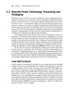
2.3 Discrete Power Technology: Processing and Packaging
From Wall to Board 20
Power MOSFET Technology Basics
Package Technologies 23
2.4 Ongoing Trends 24
vii
21
20
viii
3
Contents
Circuits
...............................................................................
Part I Analog Circuits 26
3.1 Transistors
26
NPN 26
PNP 27
Trans-Conductance 27
Transistor as Transfer-Resistor 28
Transistor Equations 29
MOS versus Bipolar Transistors 30
3.2 Elementary Circuits
32
Current Mirror 32
Current Source 32
Differential Input Stage 33
Differential to Single Input Stage
Buffer 35
3.3 Operational Amplifier (Opamp)
34
35
Inverting and Non-Inverting Inputs 36
Rail to Rail Output Operation 37
CMOSOpamp 37
Opamp Symbol and Configurations 38
DC Open Loop Gain 38
AC Open Loop Gain 39
3.4 Voltage Reference
41
Positive TC of AVBE 41
Negative TC of VBE 4 1
Build a AVBE 42
Building a Voltage Reference 43
Fractional Band-Gap Voltage Reference 44
3.5 Voltage Regulator
46
3.6 Linear versus Switching
3.7 Switching Regulators
48
49
3.8 Buck Converters 49
Switching Regulator Power Train 50
Output Capacitor 52
Electrolytic Capacitors and Transient Response
Ceramic Capacitors 53
Losses in the Power Train 55
The Analog Modulator 56
Driver 57
52
25
Contents ix
Switching Regulator Block Diagram 58
Switching Regulator Control Loop 58
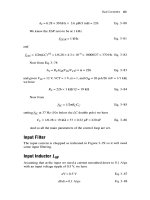
Input Filter 61
Input 1nduct;r L , 6 1
Input Capacitor 62
Current Mode 63
3.9 Flyback Converters
Part I1 Digital Circuits
3.10 Logic Functions
64
66
67
NANDGate 67
Set-Reset R Flip-Flop 67
Current Mode with Anti-Bouncing Flip-Flop
4
68
....................................
DC-DC Conversion Architectures
4.1 Valley Control Architecture
71
71
Peak and Valley Control Architectures 72
Transient Response of Each System 75
Valley Control with FAN5093 76
Conclusion 79
4.2 Monolithic Buck Converter
79
A New Design Methodology for Faster Time to Market
The Design Cycle 80
The FAN5301 8 1
The Behavioral Model 82
Light Load Operation 82
Full Load Operation 83
Over-Current 83
One Shot 83
Comparator 83
Results 84
Timing 86
Conclusion 87
4.3 Active Clamp
87
Introduction 87
Application 88
Test Results 94
Comments 96
79
x Contents
4.4 Battery Charging Techniques:
97
New Solutions for Notebook Battery Chargers
High Efficiency 97
The Smart Battery System 98
Data Conversion 98
Fast Charge 98
Battery Charger System 99
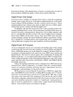
4.5 Digital Power
100
Control Algorithm of Modern Switching Regulators:
Analog or Digital? 100
Fast Switchmode Regulators and Digital Control 103
5
Offline (AC-DC) Architectures
5.1 Offline Power Architectures
.......................................
107
107
Introduction 107
Offline Control 108
PFC Architecture 1 11
DC-DC Conversion Down to Low Voltage
Future Trends 1 18
116
5.2 Power AC Adapter: Thermal and Electrical Design
119
Introduction: The Challenge 119
AC Adapter Power Dissipation 1 19
AC Adapter Case Temperature 120
Active and No-load Operation 12 1
Development of a Solution 121
Conclusion 124
6
Power Management of Ultraportable Devices
..............125
6.1 Power Management of Wireless Computing and
Communications Devices 125
The Wireless Landscape 125
Power Management Technologies for Wireless 126
Cellular Telephones 127
Wireless Handheld 129
Charge 131
Protection and Fuel Gauging 131
Convergence of Cellular Telephone and Handheld 132
Future Architectures 133
xi
Contents
6.2 Power Management in Wireless Telephones:
Subsystem Design Requirements 134
Smart Phone Subsystems
Display Board 13.5
Keypad Board 136
Main Board 136
Battery Pack 137
AC Adapter 138
134
6.3 Powering Feature-Rich Handsets
139
Growing Complexity and Shrinking Cycle Time
Power Management Unit I40
Low Dropouts (LDOs) 141
139
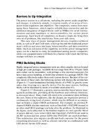
6.4 More on Power Management Units in Cell Phones
Barriers to Up-Integration 143
PMU Building Blocks 143
CPU Regulator 144
Low Dropout Block 14.5
The Microcontroller 146
The Microcontroller Die 147
Processing Requirements 148
Microcontroller-Driven Illumination System
142
148
6.5 Color Displays and Cameras Increase Demand
on Power Sources and Management 150
Digital Still Camera 1.5 1
Camera Phones 1.52
Power Minimization 15.5
Untethered Operation 1.55
7
Computing and Communications Systems
..........
7.1 Power Management of Desktop and Notebook Computers
Power Management System Solution for a
Pentium I11 Desktop System 158
Power Management System Solution for
Pentium IV Systems (Desktop and Notebook)
Desktop Systems 162
Powering the Silver Box 168
Notebook Systems 168
Future Power Trends 173
160
157
157
xii Contents
7.2 Computing and Data Communications Converge
at the Point of Load 174
The Proliferation of Power Supplies 174
Telecom Power Distribution 174
Computing Power Distribution 175
Multiphase Buck Converter for POLS and VRMs
Conclusion 177
176
7.3 Efficient Power Management ICs Tailored
for DDR-SDRAM Memories 178
Introduction 178
DDR Power Management Architecture 178
Worst Case Current Consumption 179
Average Power Consumption 180
Transient Operation 181
Standby Operation 181
Linear versus Switching 182
Second Generation DDR-DDR2
182
FAN5236 for DDR and DDR2 Memories 183
Future Trends 185
7.4 Power Management of Digital Set-Top Boxes
185
Set-Top Box Architecture 185
Power Management 186
High Power Set-Top Boxes 186
Low Power Set-Top Boxes 190
Conclusion 192
7.5 Power Conversion for the Data Communications Market
Introduction 192
Current Environment with Separate Networks
Migration to Converged Voice/Data/Video IP
Telecom 4 8 V DC Power Distribution 193
Datacom AC Power Distribution 194
Conclusion 198
8
Future Directions and Special Topics
193
193
..............
8.1 Beyond Productivity and Toys:
Designing ICs for the Health Care Market
199
8.2 Power Management Protocols Help Save Energy
ACPI 201
Motherboard (DC-DC) Voltage Regulators
192
20 1
200
199
Contents xiii
Offline (AC-DC) Voltage Regulators with Power
Factor Correction (PFC) 202
Green Power (Energy Management) 203
New Low Power System Requirements 204
Conclusion 205
8.3 Heat Disposal in Electronics Applications
205
Active versus Passive Cooling 205
Limits of Passive Cooling 206
Active Cooling 206
Active Cooling-Yes or No? 207
Active Cooling Implementation 209
8.4 Web Based Design Tools 21 1
The Tools on the Web
21 1
8.5 Motor Drivers for Portable Electronic Appliances 2 13
Introduction 2 13
Camera Basics 2 13
Motors and Motor Drivers 2 14
Driving Implementation 2 14
Efficiency 2 16
DSC Power Consumption 216
Conclusion 2 16
A
Fairchild Specifications for FAN5093 ............................
219
B
Fairchild Specifications for FAN4803 ............................
237
C
Fairchild Specifications for FSD210 and FSD200
D
Fairchild Specifications for FAN5307
........251
F
............................
Fairchild Specifications for ACE1502............................
Fairchild Specifications for FAN5236............................
G
Fairchild Specifications for FAN8702
E
..............
Glossary ............................................................................
Further Reading
Index
...............................................................
..................................................................................
271
285
319
341
359
371
373
At $13 billion and roughly five percent of the total semiconductor market (2004
data) the power semiconductor market is big and growing fast, typically outgrowing
the rest of the semiconductor market.
Modern electronic appliances, while exhibiting increasing functionality, are
also expected to consume little power, for reasons of portability, thermal performance, and environmental considerations.
This book is an important contribution to the understanding of the many facets
of this market, from technology to circuits, electronic appliances, and market
forces at work.
The author’s broad industry experience built in almost three decades of design,
application, and marketing of analog and power management devices is reflected in
the breadth of this book. Topics discussed range from fundamentals of semiconductor physics, to analog and digital circuit design and the complex market dynamics
driving the semiconductor business. The author displays in this work a unique ability to reduce complex issues to simple concepts. The book makes good reading for
the marketing engineer or business hi-tech professional wanting a quick refresh of
integrated circuits and power management design, as well as the technologist wanting to expand his market horizons. The timely market and technical information
also serves as excellent reference material for students interested in entering the
power management field.
Seth R. Sanders, Professor
Electrical Engineering and Computer
Sciences Department
University of California, Berkeley
xv
How to Use This Book
This book discusses state-of-the-art power management techniques of
modern electronic appliances relying on such Very Large Scale Integration (VLSI) chips as CPUs and DSPs.
It also covers specific circuit design issues and their implications,
including original derivation of important expressions.
This book is geared toward systems and applications, although it
also gets into the specific technical aspects of discrete and integrated
solutions, like the analysis of circuits within the power chips which
power PCs and other modern electronics.
The first half of this book is a good complement to classic semiconductor text books because it deals with the same complex issues in a
more conversational way. It avoids completely the use of complex
expressions and minimizing the use of formulas to useful ones, that
allow us to plug values in and get an actual result.
The second half of the book is a broad review of the modern technology landscape seen through the eyes of the power management engineer, continually challenged by the rising complexity of modern
electronic appliances.
Scope
In this book, power management is covered in its many facets, including
semiconductor manufacturing processes, packages, circuits, functions,
and systems. The first chapter is a general overview of the semiconductor industry and gives a glimpse of its many accomplishments in a relatively short time. Semiconductor processes and packages are discussed
in the second chapter. Great effort has been put here in explaining complex concepts in conversational and intuitive fashion. Chapter 3 is a
guided “tour de force” in analog design building from the transistor up
to higher level functions and leading to the implementation of a
xvii
xviii
Preface
complete voltage regulator. In chapter 4 we discuss a number of popular
DC-DC voltage regulation architectures, each responding to specific
requirements demanded by the application at hand. Similarly in chapter 5
we move on to discuss AC-DC architectures for power conversion. After
the technical foundation is laid with these first 5 chapters, we move to analyze some of the most popular electronic appliances. In chapter 6 we cover
ultra portable appliances such as cellular telephones, Personal Digital
Assistants (PDAs) and Digital Still Cameras (DSCs) and discuss the amazing success of these devices and the trend toward convergence leading to
smart phones that incorporate PDAs, DSCs, Global Positioning Systems
(GPS), Internet appliances and more into one small handheld device. Then
in chapter 7 we cover specifically the desktop PC, a resilient device which
continues to reinvent itself and defeat the many attempts by competing
platforms to make it obsolete. Then we go into portable computing with
the notebook PC aspiring to claim the center stage for the coming age of
“computing anywhere, anytime.” Finally some special power management
topics are covered in chapter 8. In closure the appendix section provides
more in dept information about parts discussed in the chapters.
Ac knowIed g me nts
Thanks to Fairchild Semiconductor for sponsoring this book, to Portelligent for providing some of the beautiful pictures and to Jim Holt and
Steven Park for proofreading chapter 2. And finally thanks to Melissa
Parker and Robert Kern of TIPS Technical Publishing for their careful
editing and composition.
About the Author
Reno Rossetti is a published author of technical articles for the major electronics trade magazines, power management developer, mentor, architect,
and speaker. He holds a doctorate in electrical engineering from Politecnico of Torino, Italy and a Degree in Business Administration from Bocconi University of Milan, Italy. He has more than 25 years experience in
the semiconductors industry, covering integrated circuit design, semiconductor applications and marketing roles. He is currently the director of
Strategy for the Integrated Circuits Group at Fairchild Semiconductor, a
leading Semiconductor manufacturer providing innovative solutions for
power management and power conversion.
Over the years he has designed several innovative power conversion
and management solutions for Desktop and Portable System Electronics
and CPUs. His patented “Valley Control” architecture (patent issued in
Preface xix
2000) became a leading control architecture powering many generations
of voltage regulators controllers for personal computer central processing
units (CPUs), He defined and released to production the first “Integrated
Power Supply,” LM2825, a full power supply, complete with magnetics
P
and capacitors, confined in a standard dip 24 package and produced with
standard IC manufacturing packaging technology. This resulted in a reliable and superior power supply with a mean time before failure of 20 million hours and density of 35W/cubic inch. It received several awards,
including 1996 product of the year for EETimes and EDN. More recently
he has been concerned with and created intellectual property (IP) for
advanced power management aspects including application of microelectro-mechanical (MEM) technologies to power supplies and untethered
power distribution systems. Rossetti holds several patents in the field of
voltage regulation and power management. His articles and commentaries
have appeared in the main electronics magazines in the United States,
Europe and Asia (EETimes, Planet Analog, PCIM, etc.).
1.I Technology Landscape
Power management is, literally and metaphorically, the hottest area in
computing and computing appliances.
In 1965, while working at Fairchild Semiconductor, Gordon Moore
predicted that the number of transistors in an integrated circuit would
double approximately every two years. Moore’s law, as his observation
has been dubbed, has so far been the foundation of the business of personal computing and its derivative applications. With its publication in
Electronics magazine on April 19‘h, 1965, Moore’s law was introduced
to the world, along with its profound technological, business, and financial implications.
As long as new computers continue to deliver more performanceand Moore’s law says they will-people will continue to buy them.
Whether people get bored with old technology or simply outgrow it,
outdated computers seem to have little value. Hence, people are only
willing to pay for the additional value of a new product, compared to the
old one, not the value of a product in its entirety. This means consumers
want to pay roughly the same price or even less for the new product as
for the old. In essence they want the old technology for free and are willing to pay only for the new one.
Financially, building the facilities to produce smaller and smaller
transistors requires billions of dollars of investment. For every new generation of chips, the old facility is either scrapped or used to produce
some electronics down the food chain. A new facility has to be built
1
2 Chapter 1 Introduction
with better foundations, better concrete, and better machinery. Technologically, designing such dense chips is becoming increasingly complex,
requiring new tools for simulation, production, and testing.
The combination of financial and technological constraints are such
that it takes roughly two years to transition from one chip generation to the
next, another interpretation of Moore’s law.
Figure 1-1 shows how one function can be implemented in smaller
and smaller chips as the capacity to resolve ever-smaller minimum features improves.
Figure 1-1
Moore’s law leads to ever denser chips.
Figure 1-2 shows the progression of Pentium CPUs enabled by Moore’s
law. Each new CPU requires a specialized voltage regulator module (VRM),
accurately specified by Intel. As chips become denser their current consumption rises steadily. With the Pentium IV, a single-phase ( 1 0 ) voltage regulator
is no longer sufficient. Recently, aggressive power management techniques
inside the CPU, process enhancements like low K dielectrics, copper interconnects, strained silicon, and more recently dual-core CPUs have begun
Technology Landscape 3
Figure 1-2
Moore’s law delivers new computing platforms.
slowing down the upward spiral of power consumption. Beginning with the
Centrino mobile wireless platform, even Intel has come to admit that performance can no longer be identified with clock speed (say a 3 GHz Pentium
IV), but with a more global value judgment including speed of task execution, small size, wireless connectivity, and low power consumption.
The pace of such progression greatly escalates the complexity of all
modern VLSI (Very Large Scale Integration) circuits, not just the PC
CPU. With each transistor releasing more heat at a faster operating speed,
the heat released by these complex chips is becoming difficult to handle.
The heat problem is compounded by the fact that not only does the CPU
get hotter, but so do the chipset, the graphics, and any other chip on the
mot herboard.
Power consumption containment dictates that each new generation of
PC motherboards utilizes increasingly customized voltage regulators for
each active load. In Figure 1-3 we show the transition from two voltage
regulators for Pentium CPUs up to eight voltage regulators for the Pentium
111, which power CPU periphery, the CPU, termination, the clock, memory, north bridge, AGP graphics, and stand-by.
Power management is all about feeding these power-hungry chips the
energy they need to function while controlling and disposing of the heat
by-product. Power management must progress faster than Moore’s law in
order to keep the computing business profitable.
4 Chapter 1 Introduction
4
vCC,VID
Vlio
L
vCC,VID
VI/O
VTT
VCLK
VTT
VCLK
VMEM
VNBRIDGE
VAGP
Pentium
Motherboard
Pentium II
Motherboard
VSTDBY
Pentium 111
Motherboard
Figure 1-3
Next generation motherboards require a higher number of
specialized regulators.
1.2 A Young Industry after All
Electronic gadgets are such a part of our daily lives that it is hard to believe
that the electronics industry as a whole is younger than most baby boomers.
This electronics revolution began in 1948 with William Shockley's invention of the solid state transistor and continues unabated at today. The first
transistors were made of germanium and it was not until 1954 that silicon
became a popular material. The first silicon transistors where built with a
photolithographic technique known as the mesa process, a form of contact
printing still conceptually at the base of any modern semiconductor process. As the name implies, these early transistors had an irregular surface
like a mesa rock formation or a tiered wedding cake if you will. A fundamental step forward was Fairchild Semiconductor's invention of the planar
process, in which the surface of the transistor remained flat and the various
doping materials were simply diffused inside the silicon wafer surface. In
the planar transistor in Figure 1 - 4 the smaller disk in the center is the emitter contact, lying on top of the second disk, the emitter. The bigger lopsided
disk is the base and the lopsided doughnut inside it is the base contact. The
collector is the entire dark square making up the rest of the picture. The creation of the planar process was a fundamental step in the creation, also by
Fairchild, of the Integrated Circuit (IC), in which many such transistors
could be "printed" on a flat silicon wafer. Figure 1-5 is the first integrated
circuit-a set-reset flip-flop logic device.
A Young Industry after All 5
Figure 1-4
The first planar transistor (1959).
Figure 1-5
The first IC, a Set-Reset Flip-Flop (1961).
The Fairchild chip shown in Figure 1-5, vintage 1961, is 1.8 mm2 and
integrates four transistors and five resistors, barely visible under the spidery looking metal layer on the top, that make up the interconnections and
contacts to the external world. Consider that in 2005 the dual core Montecito CPU integrates 1.72 billion transistors in 596 mm2. Hence the integrated circuit process goes from a density of two transistors per square
millimeter to three million transistors per square millimeter in less than
fifty years. From a functional stand-point the next important step is the
invention of the operational amplifier, the king of the analog world and a
fundamental building block in power management integrated circuits. The
first operational amplifier, the uA702, was designed at Fairchild by Robert
Widlar. He subsequently designed the uA709 (Figure 1-6). This opamp
6 ChaDter 1 Introduction
Figure 1-6
uA709 is the first operational amplifier of wide use in the
industry (1965).
has 14 bipolar transistors and 15 resistors integrated in a 0.6 in2 die and at
its inception (1965) sold for one hundred dollars. Accounting for inflation,
one hundred dollars in 1965 corresponds to six hundred dollars in actual
value and that makes the uA709 more glamorous in its own time than a
modern Pentium IV. As a corollary and as proof of the longevity of analog
products, you can still buy a uA709 today but the price is a small fraction
of a dollar.
Figure 1-7 shows the first planar bipolar power transistor incorporating a thin-film emitter resistor process. It was produced at Fairchild. The
two identical undulated shapes show the two emitters, the square shape
surrounding them is the base, and the dark surrounding area is the collector. The stubs are gold wires bonded to the two emitters and to the base
and connecting to the external contact pins. Bipolar power transistors have
been the workhorse of the power semiconductor industry for a long time
but recently have been almost entirely supplanted by their CMOS counterparts, which are more efficient especially in static operation.
Figure 1-8 shows a modern PowerTrenchTM discrete power transistor
by Fairchild. This device integrates ten million cells, or elementary MOSFET transistors, in parallel in a small space yielding very low “on state”
resistance. Discrete power MOSFETs like this one, in conjunction with
switching regulator controllers, enable the delivery of huge amounts of
power with unprecedented levels of efficiency.
Finally a true power management integrated circuit, the RC505 I , is
shown in Figure 1-9. In 1988 Fairchild’s RC.505 1 pioneered the use of
switching regulators in PCs, powering a Pentium I1 CPU by delivering
17.1 A in performance mode-a hefty amount of current at the time. This IC
incorporates on a single die the equivalent of many operational amplifiers
plus two driver stages that are hefty enough to drive two external MOSFET
A Young Industry after All 7
Figure 1-7
First planar power transistor incorporating a thin-film emitter
resistor process (1964).
Figure 1-8
A 10 million cells per square inch PowerTrenchTMMOSFET
technology ( 1997).
transistors such as the one in Figure 1-8 in synchronous rectification mode of
operation.
As these images have shown, in the last fifty years our semiconductor
processes have gained tremendous efficiencies, becoming 1.5 million
times denser. It is expected that in 201 1 semiconductor technology will be
able to resolve 12 nanometers, which is roughly the diameter of a DNA
strand and only 100 times the diameter of a hydrogen atom. After that it is
8 ChaDter 1 Introduction
Figure 1-9
RC505 1 pioneers the use of switching regulators in PCs,
powering a Pentium I1 CPU in 1998.
widely believed that silicon will run out of steam and new materials will
be necessary. A modern CPU, in the class of a Pentium IV, cranks out
3000 Million Instructions Per Second (MIPS) and consumes 100 W, an
amount of power already difficult to handle even with the aid of fans and
active cooling devices. On the other hand the human brain consumes 20 W
and cranks out 100 million MIPS. That makes the brain more efficient
than silicon by 165,000MIPS per Watt. Perhaps this is a clue as to where
we should search for a material to come after whatever succeeds silicon.
2.1 Introduction
Power management is generally accomplished by a combination of
small signal transistors acting as the brain, power transistors acting as
solid state switches that control the power flow from the source to the
load, and passive components like resistors, capacitors, and inductors,
acting as sensing and energy storing elements. A semiconductor integrated circuit can incorporate on a single die a large number of small
signal transistors as well as limited values of passive components (resistors, capacitors, and lately even inductors) and power transistors carrying a few Amperes. For larger levels of power, external discrete
transistors built with specialized processes are utilized in conjunction
with the IC. In this chapter we will see how ICs and discrete transistors
require very different methods of fabrication. We will first discuss the
integrated circuits typically incorporating the desired power management control algorithm and the process and package technologies utilized for their construction. Subsequently we will discuss the discrete
power transistors, called to duty when the power levels cannot be handled monolithically by the integrated circuit, and the process and package technologies utilized for their construction.
9
10 Chapter 2 Power Management Technologies
2.2 Integrated Circuits Power Technology:
Processing and Packaging
The power of the integrated circuit process lies in its ability to etch a high
number of electrical components on a small silicon die and interconnect
them to perform the desired actuation function. The main electrical components on board an IC are
Bipolar NPN transistors
Bipolar PNP transistors
Diodes
CMOS transistors
DMOS transistors
Resistors
Capacitors
The electrical properties of some of these components are discussed
in Chapter 3. In this section we will illustrate the physical structure of
these components as they are generated on the surface of a silicon die.
Diodes and Bipolar Transistors
Semiconductor crystals derive their amplification properties from bringing
together materials of opposite electrical properties, namely N-type and Ptype materials.
N-type materials are materials that, even if neutrally charged, have an
excess of free electrons, or negative charges. In other words these electrons are very weakly tied to their nucleus and hence easy to move around
in the form of an electric current.
In homogeneous materials atoms bond together by sharing their outer
shell electrons: a kind of holding hands by sharing one electron with a
neighbor atom. In the case of silicon (column IV of the Periodic Table of
Elements) each atom shares its four outer shell electrons with four neighbor atoms. If we now introduce inside silicon one atom from column V of
the Periodic Table of Elements, namely one having five outer shell electrons, this atom will bond with four neighboring silicon atoms but will
have an excess of one electron un-bonded or free to move around. As this
electron moves around, the foreign atom is left with a positively charged
nucleus. Notice that the entire compound is still electrically balanced but
the only difference now is that we have an electron that is much easier to
Integrated Circuits Power Technology. Processing and Packaging
11
move around. Column V elements like phosphorus (P), arsenic (As), and
antimony (Sb) are called donor materials because they produce an excess
of electrons inside column IV materials like silicon. Similarly if we introduce inside silicon one atom from column 111 of the Periodic Table of Elements, namely one having three outer shell electrons, this atom will bond
with three neighboring silicon atoms but the fourth silicon neighbor will
not get an electron. A positively charged ‘hole’ is created, namely an
incomplete bond between two atoms made of one single electron instead
of two. Eventually due to thermal agitation this hole will get filled by an
electron. This means that the foreign atom has now an extra electron and is
left negatively charged, while somewhere out there a silicon atom is missing an electron and is hence positively charged. In other words, the hole is
moving freely around the silicon lattice. Column 111 elements like boron
( B ) , gallium (Ga), indium (In), and aluminum (Al) are called acceptor
materials because they readily accept an electron from a nearby siliconsilicon bond creating an excess of holes inside silicon.
A material doped with donors, meaning that it has an excess of negatively charged free electrons, is referred to as an N-type material, while
one doped with acceptors, meaning that it has an excess of positively
charged holes, is referred to as a P-type material. An N- and a P-type
material brought together will form a junction. The simplest semiconductor element, the rectifying diode in Figure 2-1, is formed by such a junction between a P- and an N-type material. A positive potential applied to
the P side will push the excess of holes toward the junction where they will
recombine with excess electrons in the N-type material, sustaining a current flow in this “forward” direction. Most of the current in the P region is
made by the movement of holes, while most of the current in the N region
is created by moving electrons. This device is called bipolar, referring to a
conduction mechanism based both on electrons and holes. If a negative
potential is applied to the P-material, and a positive one is applied to the
N-material, the charges are pushed away from the junction, resulting in
zero conduction. The property of passing current only in one direction is
the rectifying effect of a diode.
Figure 2-1 illustrates the diode conduction mode, in which a forward
bias voltage V pushes a current I through the diode. Notice that the physical current in the wire is made of electrons (represented by negative circles) moving i n the opposite direction of the conventionally positive
current. Inside the diode the current is made of electrons in the N-material
and holes (positive circles) inside the P-materials. The P-to-metal contact
(anode) provides a mechanism for exchanging holes in the semiconductor
for electrons which can travel in the external circuit.
A diode is a two terminal device, which, in conduction mode, yields
from the cathode (N side) the same amount of current injected from the
12 Chapter 2 Power Management Technologies
Figure 2-1
Diode in conduction mode.
anode (P side). A diode is a passive device lacking the ability to amplify,
or modulate such flow of current.
Amplification requires a third terminal with the ability to modulate
the current flow.
If we add a P to the N side of our PN junction, we create a PNP structure. The PNP structure is a three terminal device with two junctions, the PN
junction, or emitter-base junction, normally positively biased, and the
NP junction, or base collector junction, normally negatively biased. If the
intermediate N layer (base) is thin enough and the base-emitter junction is
forward biased, a positive charge injected from the emitter can reach the
collector without significant recombination in the base. While the charge
moves from one side (emitter) to the other (collector), its amount is determined by the magnitude of the positive potential V B E applied to the forward-biased base-emitter junction (see Figure 2-2). A small voltage
variation in this junction produces a large current variation in the collector.
On the other hand, the thin base assures little charge recombination in the
base, namely a small current flow in the base, need be supplied in order to
sustain a large current flow from the emitter to the collector. Typically a
1 pA current in the base can sustain a 100 pA current flow from emitter to
collector, resulting in a gain of 100 from input (base) to output. This is the
amplifying effect in a PNP transistor. A PNP transistor moves charges
from a positive potential to a grounded (zero potential) load; this is
referred to as current sourcing. If the load is at a positive potential then the
dual of the PNP, the NPN transistor (see Figure 2-3), will be able to move
charges from the positively biased load to ground. As for the diode, the
PNP transistor (or its dual, the NPN transistor) is a bipolar device because
its conduction mechanism is based on both electrons and holes. For
Integrated Circuits Power Technology: Processing and Packaging 13
Figure 2-2
PNP transistor in conduction mode.
Figure 2-3
NPN transistor in conduction mode.
example in the PNP transistor, the bulk of the current flow is made of
holes, the majority carriers in emitter and collector but minority carriers in
the base. In the base a small percent (0.5%) of holes recombines with electrons, which are continuously supplied as base current. The base current
also sustains a small current of electrons that flows from the base to the
emitter (another 0.5% of the collector current). As explained earlier, a total
1% of the collector current-is necessary to susbase current-typically
tain the transistor conduction state.