MOdern control systems 12th by dorf
Bạn đang xem bản rút gọn của tài liệu. Xem và tải ngay bản đầy đủ của tài liệu tại đây (32.5 MB, 1,111 trang )
Design Examples and Design Problems (DP)
CHAPTER 1
PAGE
22
Example Hybrid Fuel Vehicles
23
Example Wind Power
24
Example Embedded Computers
28
Example Smart Grid Control Systems
30
Example Rotating Disk Speed Control
Example Insulin Delivery Control System 31
32
Example Disk Drive Read System
46
CDP1.1 Traction Drive Motor Control
46
Automobile Noise Control
DP1.1
Automobile Cruise Control
46
DP1.2
46
DP1.3
Dairy Farm Automation
46
DPI .4
Welder Control
46
DPI .5
Automobile Traction Control
47
DP1.6
Hubble Telescope Vibration
47
DPI.7
Nanorobotics in Medicine
47
DP1.8
Human Transportation Vehicle
CHAPTER 2
Example Photovoltaic Generators
Example Fluid Flow Modeling
Example Electric Traction Motor Control
Example Mechanical Accelerometer
Example Laboratory Robot
Example Low-Pass Filter
Example Disk Drive Read System
CDP2.1 Traction Drive Motor Control
Selection of Transfer Functions
DP2.1
DP2.2
Television Beam Circuit
DP2.3
Transfer Function Determination
DP2.4
Op Amp Differentiating Circuit
Grandfather Clock Pendulum
DP2.5
CHAPTER 3
Example Modeling the Orientation of a
Space Station
Example Printer Belt Drive
Example Disk Drive Read System
CDP3.1 Traction Drive Motor Control
Shock Absorber for Motorcycle
DP3.1
Diagonal Matrix Differential
DP3.2
Equation
Aircraft Arresting Gear
DP3.3
Bungi Jumping System
DP3.4
State Variable Feedback
DP3.5
CHAPTER 4
Example English Channel Boring
Machines
Example Mars Rover Vehicle
Example Blood Pressure Control
Example Disk Drive Read System
CDP4.1 Traction Drive Motor Control
DP4.1
Speed Control System
DP4.2
Airplane Roll Angle Control
91
94
104
106
109
111
128
155
155
155
155
155
156
193
200
209
230
230
230
230
230
231
254
257
259
273
296
296
297
DP43
DP4.4
DP4.5
DP4.6
DP4.7
DP4.8
Velocity Control System
Laser Eye Surgery
Pulse Generating Op Amp
Hydrobot
Unmanned Underwater Vehicles
Mobile Remote-Controlled
Video Camera
CHAPTER 5
Example Hubble Telescope Pointing
Example Attitude Control of an
Airplane
Example Disk Drive Read System
CDP5.1 Traction Drive Motor Control
Jet Fighter Roll Angle Control
DP5.1
DP5.2
Welding Arm Position Control
DP5.3
Automobile Active Suspension
DP5.4
Satellite Orientation Control
Deburring Robot for Machined
DP5.5
Parts
DC Motor Position Control
DP5.6
Three-Dimensional Cam
DP5.7
DP5.8
Spray Paint Robot
CHAPTER 6
Example Tracked Vehicle Turning
Example Robot-Controlled Motorcycle
Example Disk Drive Read System
CDP6.1 Traction Drive Motor Control
Automobile Ignition Control
DP6.1
DP6.2
Mars Guided Vehicle Control
DP6.3
Parameter Selection
Space Shuttle Rocket
DP6.4
DP6.5
Traffic Control System
DP6.6
State Variable Feedback
Inner and Outer Loop Control
DP6.7
DP6.8
PD Controller Design
CHAPTER 7
Example Wind Turbine Speed Control
Example Laser Manipulator Control
Example Robot Control System
Example Automobile Velocity Control
Example Disk Drive Read System
CDP7.1 Traction Drive Motor Control
Pitch Rate Aircraft Control
DP7.1
Helicopter Velocity Control
DP7.2
Mars Rover
DP7.3
Remotely Controlled Welder
DP7.4
High-Performance Jet Aircraft
DP7.5
Control of Walking Motion
DP7.6
Mobile Robot with Vision
DP7.7
OP Amp Control System
DP7.8
Robot Arm Elbow Joint
DP7.9
Actuator
297
297
298
298
298
299
343
346
360
379
379
379
379
380
380
380
381
381
404
406
421
438
438
439
439
439
439
439
440
440
497
500
502
505
516
543
543
543
544
544
544
545
545
545
546
DP7.10
DP7.11
DP7.12
DP7.13
DP7.14
Four-Wheel-Steered Automobile
Pilot Crane Control
Planetary Rover Vehicle
Roll Angle Aircraft Autopilot
PD Control of a Marginally
Stable Process
CHAPTER 8
Example Maximum Power Pointing
Tracking
Example Engraving Machine Control
Example Control of a Six-Legged Robot
Example Disk Drive Read System
CDP8.1 Traction Drive Motor Control
DP8.1
Automobile Steering System
DP8.2
Autonomous Planetary
Explorer-Ambler
Vial Position Control Under a
DP8.3
Dispenser
DP8.4
Automatic Anesthesia Control
Black Box Control
DP8.5
DP8.6
State Variable System Design
DP8.7
PID Controller Design
CHAPTER 9
Example PID Control of Wind Turbines
Example Remotely Controlled
Reconnaissance Vehicle
Example Hot Ingot Robot Control
Example Disk Drive Read System
CDP9.1 Traction Drive Motor Control
DP9.1
Mobile Robot for Toxic Waste
Cleanup
DP9.2
Control of a Flexible Arm
DP9.3
Blood Pressure Regulator
DP9.4
Robot Tennis Player
DP9.5
Electrohydraulic Actuator
DP9.6
Steel Strip-Rolling Mill
DP9.7
Lunar Vehicle Control
DP9.8
High-Speed Steel-Rolling Mill
DP9.9
Two-Tank Temperature Control
DP9.10 State Variable Feedback Control
DP9.11 Nuclear Reactor Control
CHAPTER 10
Example Rotor Winder Control System
Example The X-Y Plotter
Example Milling Machine Control System
Example Disk Drive Read System
CDP10.1 Traction Drive Motor Control
DPI 0.1 Two Cooperating Robots
DPI 0.2 Heading Control of a Bi-Wing
Aircraft
DPI 0.3 Mast Flight System
DP 10.4 High-Speed Train Tilt Control
DP10.5 Tape Transport Speed Control
DPI 0.6 Automobile Engine Control
546
547
547
548
DPI 0.7
DP10.8
DP10.9
DP10.10
DP10.11
548
583
585
588
602
628
628
628
628
628
630
630
631
674
678
681
700
735
735
735
735
735
735
735
738
738
738
739
739
783
787
790
802
826
826
826
826
826
828
828
Aircraft Roll Angle Control
Windmill Radiometer
Control with Time Delay
Loop Shaping
Polymerase Chain Reaction
Control
CHAPTER 11
Example Automatic Test System
Example Diesel Electric Locomotive
Example Disk Drive Read System
CDP11.1 Traction Drive Motor Control
DP11.1 Levitation of a Steel Ball
DPI 1.2 Automobile Carburetor
DPI 1.3 State Variable Compensation
DP11.4 Helicopter Control
DP11.5 Manufacturing of Paper
DP 11.6 Coupled-Drive Control
DPI 1.7 Tracking a Reference Input
CHAPTER 12
Example Aircraft Autopilot
Example Space Telescope Control
Example Robust Bobbin Drive
Example Ultra-Precision Diamond
Turning Machine
Example Digital Audio Tape Controller
Example Disk Drive Read System
CDP12.1 Traction Drive Motor Control
DP12.1 Turntable Position Control
DP12.2 Robust Parameter Design
DP12.3 Dexterous Hand Master
DP12.4 Microscope Control
DP12.5 Microscope Control
DPI 2.6 Artificial Control of Leg
Articulation
DP12.7 Elevator Position Control
DP12.8 Electric Ventricular Assist
Device
DP12.9 Space Robot Control
DP12.10 Solar Panel Pointing Control
DP12.11 Magnetically Levitated Train
DP12.12 Mars Guided Vehicle Control
DP 12.13 Benchmark Mass-Spring
CHAPTER 13
Example Worktable Motion Control
Example Fly-by-wire Aircraft Control
Example Disk Drive Read System
CDP13.1 Traction Drive Motor Control
DP13.1 Temperature Control System
DP13.2 Disk Drive Read-Write Head-
DP13.3
DP13.4
DPI3.5
DPI 3.6
Positioning System
Vehicle Traction Control
Machine-Tool System
Polymer Extruder Control
Sampled-Data System
828
828
829
830
830
873
876
888
903
903
903
903
904
904
905
905
935
935
938
940
943
958
974
974
974
974
975
976
976
977
978
978
979
979
979
979
1009
1011
1023
1034
1034
1034
1034
1035
1035
1035
Modern
Control Systems
TWELFTH EDITION
Richard C. Dorf
University of California, Davis
Robert H. Bishop
Marquette University
Prentice Hall
Upper Saddle River Boston Columbus San Francisco New York
Indianapolis London Toronto Sydney Singapore Tokyo Montreal
Dubai Madrid Hong Kong Mexico City Munich Paris Amsterdam Cape Town
Vice President and Editorial Director, ECS: Marcia J. Horton
Senior Editor: Andrew Gilfillan
Associate Editor: Alice Dworkin
Editorial Assistant: William Opaluch
Vice President, Production: Vince O'Brien
Senior Managing Editor: Scott Disanno
Production Liaison: Jane Bonnell
Production Editor: Maheswari PonSaravanan,TexTech International
Senior Operations Supervisor: Alan Fischer
Operations Specialist: Lisa McDowell
Executive Marketing Manager: Tim Galligan
Marketing Assistant: Mack Patterson
Senior Art Director and Cover Designer: Kenny Beck
Cover Images: Front: Scarlet macaw flying/Frans Lanting/Corbis; Back: Courtesy of Dr. William Kaiser
and Dr. Philip Rundel of UCLA, and National Instruments
Art Editor: Greg Dulles
Media Editor: Daniel Sandin
Composition/Full-Service Project Management: TexTech International
Lab VIEW is a trademark of National Instruments. MATLAB is a registered trademark of The Math Works, Inc.
Company and product names mentioned herein are the trademarks or registered trademarks of their respective
owners.
Copyright © 2011,2008,2005,2001 by Pearson Education, Inc., Upper Saddle River, New Jersey 07458. All rights
reserved. Manufactured in the United States of America. This publication is protected by Copyright and permissions should be obtained from the publisher prior to any prohibited reproduction, storage in a retrieval system, or
transmission in any form or by any means, electronic, mechanical, photocopying, recording, or likewise. To obtain
permission(s) to use materials from this work, please submit a written request to Pearson Higher Education,
Permissions Department, 1 Lake Street, Upper Saddle River, NJ 07458.
The author and publisher of this book have used their best efforts in preparing this book. These efforts include
the development, research, and testing of the theories and programs to determine their effectiveness. The author and
publisher make no warranty of any kind, expressed or implied, with regard to these programs or the documentation
contained in this book. The author and publisher shall not be liable in any event for incidental or consequential
damages in connection with, or arising out of, the furnishing, performance, or use of these programs.
Library of Congress Cataloging-in-Publication Data
Dorf, Richard C.
Modern control systems / Richard C. Dorf, Robert H. Bishop. — 12th ed.
p. cm.
ISBN-13:978-0-13-602458-3
ISBN-10:0-13-602458-0
1. Feedback control systems. I. Bishop, Robert H. II. Title.
TJ216.D67 2010
629.83-dc22
2010015651
Prentice Hall
is an imprint of
10
www.pearsonhighered.com
9 8 7 6 5 4 3 2 1
ISBN-13:978-0-13-602458-3
ISBN-10:
0-13-602458-0
Of the greater teachers—
when they are gone,
their students will say:
we did it ourselves.
Dedicated to
Lynda Ferrera Bishop
and
Joy MacDonald Dorf
In grateful appreciation
Contents
Preface xi
About the Authors xxii
CHAPTER
1
Introduction to Control Systems 1
1.1
1.2
1.3
1.4
1.5
1.6
1.7
1.8
1.9
1.10
1.11
CHAPTER 2
Mathematical Models of Systems 49
2.1
2.2
2.3
2.4
2.5
2.6
2.7
2.8
2.9
2.10
2.11
CHAPTER 3
Introduction 2
Brief History of Automatic Control 5
Examples of Control Systems 10
Engineering Design 17
Control System Design 18
Mechatronic Systems 21
Green Engineering 25
The Future Evolution of Control Systems 27
Design Examples 28
Sequential Design Example: Disk Drive Read System 32
Summary 34
Skills Check 35 • Exercises 37 • Problems 39 • Advanced
Problems 44 • Design Problems 46 • Terms and Concepts 48
Introduction 50
Differential Equations of Physical Systems 50
Linear Approximations of Physical Systems 55
The Laplace Transform 58
The Transfer Function of Linear Systems 65
Block Diagram Models 79
Signal-Flow Graph Models 84
Design Examples 90
The Simulation of Systems Using Control Design Software 113
Sequential Design Example: Disk Drive Read System 128
Summary 130
Skills Check 131 • Exercises 135 • Problems 141 • Advanced
Problems 153 • Design Problems 155 • Computer Problems 157 •
Terms and Concepts 159
State Variable Models
3.1
3.2
161
Introduction 162
The State Variables of a Dynamic System 162
VI
Contents
3.3
3.4
3.5
3.6
3.7
3.8
3.9
3.10
3.11
CHAPTER 4
Feedback Control System Characteristics 234
4.1
4.2
4.3
4.4
4.5
4.6
4.7
4.8
4.9
4.10
4.11
CHAPTER 5
The State Differential Equation 166
Signal-Flow Graph and Block Diagram Models 171
Alternative Signal-Flow Graph and Block Diagram Models 182
The Transfer Function from the State Equation 187
The Time Response and the State Transition Matrix 189
Design Examples 193
Analysis of State Variable Models Using Control Design Software 206
Sequential Design Example: Disk Drive Read System 209
Summary 213
Skills Check 214 • Exercises 217 • Problems 220 • Advanced
Problems 227 • Design Problems 230 • Computer Problems 231 •
Terms and Concepts 232
Introduction 235
Error Signal Analysis 237
Sensitivity of Control Systems to Parameter Variations 239
Disturbance Signals in a Feedback Control System 242
Control of the Transient Response 247
Steady-State Error 250
The Cost of Feedback 253
Design Examples 254
Control System Characteristics Using Control Design
Software 268
Sequential Design Example: Disk Drive Read System 273
Summary 277
Skills Check 279 • Exercises 283 • Problems 287 • Advanced
Problems 293 • Design Problems 296 • Computer Problems 300 •
Terms and Concepts 303
The Performance of Feedback Control Systems 304
5.1
5.2
5.3
5.4
5.5
5.6
5.7
5.8
5.9
5.10
5.11
Introduction 305
Test Input Signals 305
Performance of Second-Order Systems 308
Effects of a Third Pole and a Zero on the Second-Order System
Response 314
The 5-Plane Root Location and the Transient Response 320
The Steady-State Error of Feedback Control Systems 322
Performance Indices 330
The Simplification of Linear Systems 339
Design Examples 342
System Performance Using Control Design Software 356
Sequential Design Example: Disk Drive Read System 360
vii
Contents
5.12
CHAPTER 6
The Stability of Linear Feedback Systems 386
6.1
6.2
6.3
6.4
6.5
6.6
6.7
6.8
CHAPTER
The Concept of Stability 387
The Routh-Hurwitz Stability Criterion 391
The Relative Stability of Feedback Control Systems 399
The Stability of State Variable Systems 401
Design Examples 404
System Stability Using Control Design Software 413
Sequential Design Example: Disk Drive Read System 421
Summary 424
Skills Check 425 • Exercises 428 • Problems 430 • Advanced
Problems 435 • Design Problems 438 • Computer Problems 440
Terms and Concepts 442
The Root Locus Method
7.1
7.2
7.3
7.4
7.5
7.6
7.7
7.8
7.9
7.10
7.11
CHAPTER 8
Summary 364
Skills Check 364 • Exercises 368 • Problems 371 • Advanced
Problems 377 • Design Problems 379 • Computer Problems 382
Terms and Concepts 384
443
Introduction 444
The Root Locus Concept 444
The Root Locus Procedure 449
Parameter Design by the Root Locus Method 467
Sensitivity and the Root Locus 473
PID Controllers 480
Negative Gain Root Locus 492
Design Examples 496
The Root Locus Using Control Design Software 510
Sequential Design Example: Disk Drive Read System 516
Summary 518
Skills Check 522 • Exercises 526 • Problems 530 • Advanced
Problems 539 • Design Problems 543 • Computer Problems 549
Terms and Concepts 551
Frequency Response Methods 553
8.1
8.2
8.3
8.4
8.5
8.6
Introduction 554
Frequency Response Plots 556
Frequency Response Measurements 577
Performance Specifications in the Frequency Domain 579
Log Magnitude and Phase Diagrams 582
Design Examples 583
viii
Contents
8.7
8.8
8.9
CHAPTER 9
Stability in the Frequency Domain
9.1
9.2
9.3
9.4
9.5
9.6
9.7
9.8
9.9
9.10
9.11
9.12
CHAPTER
Frequency Response Methods Using Control Design Software 596
Sequential Design Example: Disk Drive Read System 602
Summary 603
Skills Check 608 • Exercises 613 • Problems 616 • Advanced
Problems 626 • Design Problems 628 • Computer Problems 631 •
Terms and Concepts 633
634
Introduction 635
Mapping Contours in the s-Plane 636
The Nyquist Criterion 642
Relative Stability and the Nyquist Criterion 653
Time-Domain Performance Criteria in the Frequency Domain 661
System Bandwidth 668
The Stability of Control Systems with Time Delays 668
Design Examples 673
PID Controllers in the Frequency Domain 691
Stability in the Frequency Domain Using Control Design Software 692
Sequential Design Example: Disk Drive Read System 700
Summary 703
Skills Check 711 • Exercises 715 • Problems 721 • Advanced
Problems 731 • Design Problems 735 • Computer Problems 740 •
Terms and Concepts 742
1 0 The Design of Feedback Control Systems 743
10.1
10.2
10.3
10.4
10.5
10.6
10.7
10.8
10.9
10.10
10.11
10.12
10.13
10.14
10.15
Introduction 744
Approaches to System Design 745
Cascade Compensation Networks 747
Phase-Lead Design Using the Bode Diagram 751
Phase-Lead Design Using the Root Locus 757
System Design Using Integration Networks 764
Phase-Lag Design Using the Root Locus 767
Phase-Lag Design Using the Bode Diagram 772
Design on the Bode Diagram Using Analytical Methods 776
Systems with a Prefilter 778
Design for Deadbeat Response 781
Design Examples 783
System Design Using Control Design Software 796
Sequential Design Example: Disk Drive Read System 802
Summary 804
Skills Check 806 • Exercises 810 • Problems 814 • Advanced
Problems 823 • Design Problems 826 • Computer Problems 831 •
Terms and Concepts 833
Contents
CHAPTER
11
The Design of State Variable Feedback
Systems 834
11.1
11.2
11.3
11.4
11.5
11.6
11.7
11.8
11.9
11.10
11.11
11.12
CHAPTER
Introduction 835
Controllability and Observability 835
Full-State Feedback Control Design 841
Observer Design 847
Integrated Full-State Feedback and Observer 851
Reference Inputs 857
Optimal Control Systems 859
Internal Model Design 869
Design Examples 873
State Variable Design Using Control Design Software 882
Sequential Design Example: Disk Drive Read System 888
Summary 890
Skills Check 890 • Exercises 894 • Problems 896 • Advanced
Problems 900 • Design Problems 903 • Computer Problems 906 •
Terms and Concepts 908
1 2 Robust Control Systems
12.1
12.2
12.3
12.4
12.5
12.6
12.7
12.8
12.9
12.10
12.11
12.12
CHAPTER
ix
Introduction 911
Robust Control Systems and System Sensitivity 912
Analysis of Robustness 916
Systems with Uncertain Parameters 918
The Design of Robust Control Systems 920
The Design of Robust PID-Controlled Systems 926
The Robust Internal Model Control System 932
Design Examples 935
The Pseudo-Quantitative Feedback System 952
Robust Control Systems Using Control Design Software 953
Sequential Design Example: Disk Drive Read System 958
Summary 960
Skills Check 961 • Exercises 965 • Problems 967 • Advanced
Problems 971 • Design Problems 974 • Computer Problems 980 •
Terms and Concepts 982
1 3 Digital Control Systems
13.1
13.2
13.3
13.4
13.5
910
984
Introduction 985
Digital Computer Control System Applications 985
Sampled-Data Systems 987
The z-Transform 990
Closed-Loop Feedback Sampled-Data Systems 995
X
Contents
13.6
13.7
13.8
13.9
13.10
13.11
13.12
13.13
APPENDIX A
Performance of a Sampled-Data, Second-Order System 999
Closed-Loop Systems with Digital Computer Compensation 1001
The Root Locus of Digital Control Systems 1004
Implementation of Digital Controllers 1008
Design Examples 1009
Digital Control Systems Using Control Design Software 1018
Sequential Design Example: Disk Drive Read System 1023
Summary 1025
Skills Check 1025 • Exercises 1029 • Problems 1031 •
Advanced Problems 1033 • Design Problems 1034 • Computer
Problems 1036 • Terms and Concepts 1037
MATLAB Basics
1038
References 1056
Index 1071
4 ^ WEBRESOURCES
APPENDIX B
MathScript RT Module Basics
APPENDIX C
Symbols, Units, and Conversion Factors
APPENDIX D
Laplace Transform Pairs
APPENDIX E
An Introduction to Matrix Algebra
APPENDIX F
Decibel Conversion
APPENDIX G
Complex Numbers
APPENDIX H
z-Transform Pairs Preface
APPENDIX 1
Discrete-Time Evaluation of the Time Response
Preface
MODERN CONTROL SYSTEMS—THE BOOK
Global issues such as climate change, clean water, sustainability, waste management,
emissions reduction, and minimizing raw material and energy use have caused many
engineers to re-think existing approaches to engineering design. One outcome of
the evolving design strategy is to consider green engineering.The goal of green engineering is to design products that minimize pollution, reduce the risk to human
health, and improve the environment. Applying the principles of green engineering
highlights the power of feedback control systems as an enabling technology.
To reduce greenhouse gases and minimize pollution, it is necessary to improve
both the quality and quantity of our environmental monitoring systems. One example is to use wireless measurements on mobile sensing platforms to measure the
external environment. Another example is to monitor the quality of the delivered
power to measure leading and lagging power, voltage variations, and waveform harmonics. Many green engineering systems and components require careful monitoring of current and voltages. For example, current transformers are used in various
capacities for measuring and monitoring current within the power grid network of
interconnected systems used to deliver electricity. Sensors are key components of
any feedback control system because the measurements provide the required information as to the state of the system so the control system can take the appropriate
action.
The role of control systems in green engineering will continue to expand as the
global issues facing us require ever increasing levels of automation and precision. In
the book, we present key examples from green engineering such as wind turbine
control and modeling of a photovoltaic generator for feedback control to achieve
maximum power delivery as the sunlight varies over time.
The wind and sun are important sources of renewable energy around the world.
Wind energy conversion to electric power is achieved by wind energy turbines connected to electric generators. The intermittency characteristic of the wind makes
smart grid development essential to bring the energy to the power grid when it is
available and to provide energy from other sources when the wind dies down or is
disrupted. A smart grid can be viewed as a system comprised of hardware and software that routes power more reliably and efficiently to homes, businesses, schools,
and other users of power in the presence of intermittency and other disturbances.
The irregular character of wind direction and power also results in the need for reliable, steady electric energy by using control systems on the wind turbines themselves. The goal of these control devices is to reduce the effects of wind
intermittency and the effect of wind direction change. Energy storage systems are
also critical technologies for green engineering. We seek energy storage systems that
are renewable, such as fuel cells. Active control can be a key element of effective
renewable energy storage systems as well.
xi
xii
Preface
Control engineering is an exciting and a challenging field. By its very nature, control engineering is a multidisciplinary subject, and it has taken its place as a core
course in the engineering curriculum. It is reasonable to expect different approaches
to mastering and practicing the art of control engineering. Since the subject has a
strong mathematical foundation, we might approach it from a strictly theoretical
point of view, emphasizing theorems and proofs. On the other hand, since the ultimate objective is to implement controllers in real systems, we might take an ad hoc
approach relying only on intuition and hands-on experience when designing feedback control systems. Our approach is to present a control engineering methodology
that, while based on mathematical fundamentals, stresses physical system modeling
and practical control system designs with realistic system specifications.
We believe that the most important and productive approach to learning is for
each of us to rediscover and re-create anew the answers and methods of the past.
Thus, the ideal is to present the student with a series of problems and questions and
point to some of the answers that have been obtained over the past decades. The
traditional method—to confront the student not with the problem but with the finished solution—is to deprive the student of all excitement, to shut off the creative
impulse, to reduce the adventure of humankind to a dusty heap of theorems. The
issue, then, is to present some of the unanswered and important problems that we
continue to confront, for it may be asserted that what we have truly learned and
understood, we discovered ourselves.
The purpose of this book is to present the structure of feedback control theory
and to provide a sequence of exciting discoveries as we proceed through the text
and problems. If this book is able to assist the student in discovering feedback control system theory and practice, it will have succeeded.
WHAT'S NEW IN THIS EDITION
This latest edition of Modern Control Systems incorporates the following key updates:
•
•
Q
•
•
•
•
A new section in Chapter 1 on green engineering. The role of control systems in green
engineering will continue to expand as global environmental challenges require ever
increasing levels of automation and precision.
New design problems in key chapters that illustrate control design to support green
engineering applications, such as smart grids, environmental monitoring, wind power
and solar power generation.
A new section in each chapter entitled "Skills Check" that allows students to test their
knowledge of the basic principles. Answers are provided at the end of each chapter for
immediate feedback.
A new section on the negative gain root locus.
A new section on PID tuning methods with emphasis on manual tuning and ZieglerNichols tuning methods.
Over 20% of the problems updated or newly added. With the twelfth edition we now
have a total of over 1000 end-of-chapter exercises, problems, advanced problems,
design problems, and computer problems. Instructors will have no difficulty finding
different problems to assign semester after semester.
Video solutions of representative homework problems are available on the companion
website: www.pearsonhighered.com/dorf.
Preface
xiii
THE AUDIENCE
This text is designed for an introductory undergraduate course in control systems for
engineering students. There is very little demarcation between aerospace, chemical,
electrical, industrial, and mechanical engineering in control system practice; therefore, this text is written without any conscious bias toward one discipline. Thus, it is
hoped that this book will be equally useful for all engineering disciplines and, perhaps, will assist in illustrating the utility of control engineering. The numerous problems and examples represent all fields, and the examples of the sociological,
biological, ecological, and economic control systems are intended to provide the
reader with an awareness of the general applicability of control theory to many
facets of life. We believe that exposing students of one discipline to examples and
problems from other disciplines will provide them with the ability to see beyond
their own field of study. Many students pursue careers in engineering fields other
than their own. For example, many electrical and mechanical engineers find themselves in the aerospace industry working alongside aerospace engineers. We hope this
introduction to control engineering will give students a broader understanding of
control system design and analysis.
In its first eleven editions, Modern Control Systems has been used in senior-level
courses for engineering students at more than 400 colleges and universities. It also
has been used in courses for engineering graduate students with no previous background in control engineering.
THE TWELFTH EDITION
A companion website is available to students and faculty using the twelfth edition.
The website contains all the m-files in the book, Laplace and z-transform tables,
written materials on matrix algebra and complex numbers, symbols, units, and conversion factors, and an introduction to the LabVIEW MathScript RT Module.
An icon will appear in the book margin whenever there is additional related material on the website. The companion website also includes video solutions of representative homework problems and a complete Pearson eText. The MCS website
address is www.pearsonhighered.com/dorf.
With the twelfth edition, we continue to evolve the design emphasis that historically has characterized Modern Control Systems. Using the real-world engineering problems associated with designing a controller for a disk drive read
system, we present the Sequential Design Example (identified by an arrow icon in
the text), which is considered sequentially in each chapter using the methods and
concepts in that chapter. Disk drives are used in computers of all sizes and they
represent an important application of control engineering. Various aspects of the
design of controllers for the disk drive read system are considered in each chapter.
For example, in Chapter 1 we identify the control goals, identify the variables to
be controlled, write the control specifications, and establish the preliminary system configuration for the disk drive. Then, in Chapter 2, we obtain models of the
Preface
process, sensors, and actuators. In the remaining chapters, we continue the design
process, stressing the main points of the chapters.
In the same spirit as the Sequential Design Example, we present a design problem that we call the Continuous Design Problem (identified by an arrow icon in the
text) to give students the opportunity to build upon a design problem from chapter
to chapter. High-precision machinery places stringent demands on table slide systems. In the Continuous Design Problem, students apply the techniques and tools
presented in each chapter to the development of a design solution that meets the
specified requirements.
The computer-aided design and analysis component of the book continues to
evolve and improve. The end-of-chapter computer problem set is identified by the
graphical icon in the text. Also, many of the solutions to various components of
the Sequential Design Example utilize m-files with corresponding scripts included
in the figures.
A new feature of the twelfth edition is a Skills Check section at the end of each
chapter. The section is noted with a check mark icon. In each Skills Check section,
we provide three sets of problems to test your knowledge of the chapter material.
This includes True of False, Multiple Choice, and Word Match problems. To obtain
Preface
XV
direct feedback, you can check your answers with the answer key provided at the
conclusion of the end-of-chapter problems.
PEDAGOGY
The book is organized around the concepts of control system theory as they have
been developed in the frequency and time domains. An attempt has been made to
make the selection of topics, as well as the systems discussed in the examples and
problems, modern in the best sense. Therefore, this book includes discussions on
robust control systems and system sensitivity, state variable models, controllability
and observability, computer control systems, internal model control, robust PID controllers, and computer-aided design and analysis, to name a few. However, the classical topics of control theory that have proved to be so very useful in practice have
been retained and expanded.
Building Basic Principles: From Classical to Modern. Our goal is to present a clear
exposition of the basic principles of frequency- and time-domain design techniques.
The classical methods of control engineering are thoroughly covered: Laplace transforms and transfer functions; root locus design; Routh-Hurwitz stability analysis;
frequency response methods, including Bode, Nyquist, and Nichols; steady-state
error for standard test signals; second-order system approximations; and phase and
gain margin and bandwidth. In addition, coverage of the state variable method is
significant. Fundamental notions of controllability and observability for state variable models are discussed. Full state feedback design with Ackermann's formula for
pole placement is presented, along with a discussion on the limitations of state variable feedback. Observers are introduced as a means to provide state estimates when
the complete state is not measured.
Upon this strong foundation of basic principles, the book provides many opportunities to explore topics beyond the traditional. Advances in robust control theory
are introduced in Chapter 12. The implementation of digital computer control systems is discussed in Chapter 13. Each chapter (but the first) introduces the student
to the notion of computer-aided design and analysis. The book concludes with an
extensive references section, divided by chapter, to guide the student to further
sources of information on control engineering.
Progressive Development of Problem-Solving Skills. Reading the chapters, attending
lectures and taking notes, and working through the illustrated examples are all part of
the learning process. But the real test comes at the end of the chapter with the problems. The book takes the issue of problem solving seriously. In each chapter, there are
five problem types:
•
•
Q
Q
Q
Exercises
Problems
Advanced Problems
Design Problems
Computer Problems
Preface
For example, the problem set for The Root Locus Method, Chapter 7 (see page
443) includes 28 exercises, 39 problems, 14 advanced problems, 14 design problems,
and 10 computer-based problems. The exercises permit the students to readily utilize the concepts and methods introduced in each chapter by solving relatively
straightforward exercises before attempting the more complex problems. Answers
to one-third of the exercises are provided. The problems require an extension of the
concepts of the chapter to new situations. The advanced problems represent problems of increasing complexity. The design problems emphasize the design task; the
computer-based problems give the student practice with problem solving using
computers. In total, the book contains more than 1000 problems. The abundance of
problems of increasing complexity gives students confidence in their problemsolving ability as they work their way from the exercises to the design and computerbased problems. An instructor's manual, available to all adopters of the text for
course use, contains complete solutions to all end-of-chapter problems.
A set of m-files, the Modem Control Systems Toolbox, has been developed by
the authors to supplement the text. The m-files contain the scripts from each computer-based example in the text. You may retrieve the m-files from the companion
website: www.pearsonhighered.com/dorf.
Design Emphasis without Compromising Basic Principles. The all-important topic
of design of real-world, complex control systems is a major theme throughout the
text. Emphasis on design for real-world applications addresses interest in design by
ABET and industry.
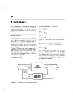
The design process consists of seven main building blocks that we arrange into
three groups:
1. Establishment of goals and variables to be controlled, and definition of
specifications (metrics) against which to measure performance
2. System definition and modeling
3. Control system design and integrated system simulation and analysis
In each chapter of this book, we highlight the connection between the design
process and the main topics of that chapter. The objective is to demonstrate different aspects of the design process through illustrative examples. Various aspects of
the control system design process are illustrated in detail in the following examples:
Q
Q
a
Q
Q
Q
•
Q
Q
Q
smart grids (Section 1.9, page 28)
photovoltaic generators (Section 2.8, page 91)
space station orientation modeling (Section 3.8. page 193)
blood pressure control during anesthesia (Section 4.8, page 259)
attitude control of an airplane (Section 5.9, page 346)
robot-controlled motorcycle (Section 6.5, page 406)
wind turbine rotor speed control (Section 7.8, page 497)
maximum power pointing tracking (Section 8.6, page 583)
PID control of wind turbines (Section 9.8, page 674)
milling machine control system (Section 10.12, page 790)
Preface
xvii
In this column remarks
relate the design topics on
the left to specific sections,
figures, equations, and tables
in the example.
Topics emphasized in this example
Establish the control goals
Shading indicates the
topics that are emphasized
in each chapter. Some chapters
will have many shaded blocks,
and other chapters will emphasize
just one or two topics.
Identify the variables to be controlled
(1) Establishment of goals,
variables to be controlled,
and specifications.
Write the specifications
1
Obtain a model of the process, the
(2) System definition
and modeling.
actuator, and the sensor
~r
Describe a controller and select key
parameters to be adjusted
(3) Control system design,
simulation, and analysis.
\'
Optimize the parameters and
analyze the performance
If the performance does not meet the
specifications, then iterate the configuration.
•
•
Q
1
If the performance meets the specifications,
then finalize the design.
diesel electric locomotive control (Section 11.9, page 876)
digital audio tape controller (Section 12.8, page 943)
manufacturing worktable control (Section 13.10, page 1009)
Each chapter includes a section to assist students in utilizing computer-aided
design and analysis concepts and in reworking many of the design examples. In
Chapter 5, the Sequential Design Example: Disk Drive Read System is analyzed
using computer-based methods. An m-file script that can be used to analyze the design
is presented in Figure 5.47, p. 362. In general, each script is annotated with comment
boxes that highlight important aspects of the script. The accompanying output of the
script (generally a graph) also contains comment boxes pointing out significant elements. The scripts can also be utilized with modifications as the foundation for solving other related problems.
XViii
Preface
IVet-JU,
Select Ka.
*
t=[0:0.01:1];
nc=[Ka*5];dc=[1]; sysc=tf(nc,dc);
ng-[1];dg-[1 20 0]; sysg-tf(ng.dg);
sys1=series(sysc,sysg); ]
sys=TeedbacK(sysi, pj); f *
J
y=step(sys,t);
plot(t,y), grid
xlabeI(Time (s)')
ylabelCy(ty)
Compute the
closed-loop
transfer function.
(a)
1.2
Ka = 60.
1
0.8
Ka = 30.
§
0.6
0.4
0.2
0
0
0.1
0.2
0.3
0.4
0.5
0.6
0.7
0.8
0.9
1
Time (s)
(b)
Learning Enhancement. Each chapter begins with a chapter preview describing
the topics the student can expect to encounter. The chapters conclude with an
end-of-chapter summary, skills check, as well as terms and concepts. These sections reinforce the important concepts introduced in the chapter and serve as a
reference for later use.
A second color is used to add emphasis when needed and to make the graphs
and figures easier to interpret. Design Problem 4.4, page 297, asks the student to determine the value of K of the controller so that the response, denoted by Y(s), to a
step change in the position, denoted by R(s), is satisfactory and the effect of the disturbance, denoted by Td(s)> is minimized.The associated Figure DP4.4, p. 298, assists
the student with (a) visualizing the problem and (b) taking the next step to develop
the transfer function model and to complete the design.
xix
Preface
Control ler
Laser
Argon laser
Ophthalmologist
«1
systemjl|
Fiber optics
* IlidLJJI
Patient
(a)
W
Controller
R(s)
position
,- +
Camera and
laser
.v(.v + 1 )(s + 4)
-+Ks)
(b)
THE ORGANIZATION
Chapter 1 Introduction to Control Systems. Chapter 1 provides an introduction to
the basic history of control theory and practice. The purpose of this chapter is to
describe the general approach to designing and building a control system.
Chapter 2 Mathematical Models of Systems. Mathematical models of physical systems in input-output or transfer function form are developed in Chapter 2. A wide
range of systems (including mechanical, electrical, and fluid) are considered.
Chapter 3 State Variable Models. Mathematical models of systems in state variable form are developed in Chapter 3. Using matrix methods, the transient response
of control systems and the performance of these systems are examined.
Chapter 4 Feedback Control System Characteristics. The characteristics of feedback control systems are described in Chapter 4. The advantages of feedback are
discussed, and the concept of the system error signal is introduced.
XX
Preface
Chapter 5 The Performance of Feedback Control Systems. In Chapter 5, the performance of control systems is examined. The performance of a control system is
correlated with the s-plane location of the poles and zeros of the transfer function of
the system.
Chapter 6 The Stability of Linear Feedback Systems. The stability of feedback systems is investigated in Chapter 6. The relationship of system stability to the characteristic equation of the system transfer function is studied. The Routh-Hurwitz
stability criterion is introduced.
Chapter 7 The Root Locus Method. Chapter 7 deals with the motion of the roots
of the characteristic equation in the s-plane as one or two parameters are varied.
The locus of roots in the s-plane is determined by a graphical method. We also
introduce the popular PID controller and the Ziegler-Nichols PID tuning method.
Chapter 8 Frequency Response Methods. In Chapter 8, a steady-state sinusoid
input signal is utilized to examine the steady-state response of the system as the frequency of the sinusoid is varied. The development of the frequency response plot,
called the Bode plot, is considered.
Chapter 9 Stability in the Frequency Domain. System stability utilizing frequency
response methods is investigated in Chapter 9. Relative stability and the Nyquist
criterion are discussed.
Chapter 10 The Design of Feedback Control Systems. Several approaches to
designing and compensating a control system are described and developed in
Chapter 10. Various candidates for service as compensators are presented and it is
shown how they help to achieve improved performance.
Chapter 11 The Design of State Variable Feedback Systems. The main topic of
Chapter 11 is the design of control systems using state variable models. Full-state
feedback design and observer design methods based on pole placement are discussed. Tests for controllability and observability are presented, and the concept of
an internal model design is discussed.
Chapter 12 Robust Control Systems. Chapter 12 deals with the design of highly
accurate control systems in the presence of significant uncertainty. Five methods for
robust design are discussed, including root locus, frequency response, ITAE methods for robust PID controllers, internal models, and pseudo-quantitative feedback.
Chapter 13 Digital Control Systems. Methods for describing and analyzing the
performance of computer control systems are described in Chapter 13. The stability
and performance of sampled-data systems are discussed.
Appendix A MATLAB Basics
Preface
XXI
ACKNOWLEDGMENTS
We wish to express our sincere appreciation to the following individuals who have
assisted us with the development of this twelfth edition, as well as all previous editions: Mahmoud A. Abdallah, Central Sate University (OH); John N. Chiasson, University of Pittsburgh; Samy El-Sawah, California State Polytechnic University,
Pomona; Peter J. Gorder, Kansas State University; Duane Hanselman, University of
Maine; Ashok Iyer, University of Nevada, Las Vegas; Leslie R. Koval, University of
Missouri-Rolla; L. G. Kraft, University of New Hampshire; Thomas Kurfess, Georgia Institute of Technology; Julio C Mandojana, Mankato State University; Luigi
Mariani, University of Padova; Jure Medanic, University of Illinois at UrbanaChampaign; Eduardo A. Misawa, Oklahoma State University; Medhat M. Morcos,
Kansas State University; Mark Nagurka, Marquette University; D. Subbaram
Naidu, Idaho State University; Ron Perez, University of Wisconsin-Milwaukee;
Carla Schwartz, The MathWorks, Inc.; Murat Tanyel, Dordt College; Hal Tharp,
University of Arizona; John Valasek, Texas A & M University; Paul P. Wang, Duke
University; and Ravi Warrier, GMI Engineering and Management Institute.
OPEN LINES OF COMMUNICATION
The authors would like to establish a line of communication with the users of
Modern Control Systems. We encourage all readers to send comments and suggestions for this and future editions. By doing this, we can keep you informed of any
general-interest news regarding the textbook and pass along comments of other
users.
Keep in touch!
Richard C. Dorf
Robert H. Bishop
rhbishop @ marquette.edu