pentair pressure relief valve engineering handbook
Bạn đang xem bản rút gọn của tài liệu. Xem và tải ngay bản đầy đủ của tài liệu tại đây (5 MB, 233 trang )
Pentair Pressure Relief Valve
Engineering Handbook
Anderson Greenwood, Crosby and Varec Products
VALVES & CONTROLS
Pentair Pressure Relief Valve Engineering Handbook
Forward
Technical Publication No. TP-V300
Copyright © 2012 Pentair Valves & Controls. All rights reserved. No part of this
publication may be reproduced or distributed in any form or by any means, or stored in a
database or retrieval system, without written permission. Pentair Valves & Controls (PVC)
provides the information herein in good faith but makes no representation as to its
comprehensiveness or accuracy. Individuals using this information in this publication
must exercise their independent judgment in evaluating product selection and
determining product appropriateness for their particular purpose and system
requirements. PVC makes no representations or warranties, either express or implied,
including without limitation any warranties of merchantability or fitness for a particular
purpose with respect to the information set forth herein or the product(s) to which the
information refers. Accordingly, PVC will not be responsible for damages (of any kind or
nature, including incidental, direct, indirect, or consequential damages) resulting from the
use of or reliance upon this information. Pentair reserves the right to change product
designs and specifications without notice. All registered trademarks are the property of
their respective owners. Printed in the USA.
PVCMC-0296-US-1203 rev 1-2015
Pentair Pressure Relief Valve Engineering Handbook
Contents
Technical Publication No. TP-V300
Table of Contents
Chapter 1 – Introduction
Chapter 2 – Terminology
I.
II.
III.
IV.
V.
VI.
General
Types of Devices
Parts of Pressure Relief Devices
Dimensional Characteristics – Pressure Relief Valves
Operational Characteristics – Pressure Relief Devices
System Characteristics
Chapter 3 – Codes and Standards
I.
II.
III.
IV.
V.
VI.
VII.
Introduction
American Society of Mechanical Engineers (ASME) Boiler and Pressure Vessel Code
International Organization for Standardization (ISO)
European Union Directives
American Petroleum Institute (API)
National Fire Protection Agency (NFPA)
National Board of Boiler and Pressure Vessel Inspectors
Chapter 4 – Design Fundamentals
I.
II.
III.
IV.
Introduction
Direct Spring Operated Pressure Relief Valves
Pilot Operated Pressure Relief Valves
Advantages and Limitations of Valve Types
Chapter 5 – Valve Sizing and Selection (USCS Units)
I.
II.
III.
IV.
V.
VI.
VII.
VIII.
IX.
Introduction
Gas/Vapor Sizing – Sonic Flow
Gas/Vapor Sizing – Subsonic Flow
Steam Sizing
Liquid Sizing
Fire Sizing
Two-Phase Flow Sizing
Noise Level Calculations
Reaction Forces
Chapter 6 - Valve Sizing and Selection (Metric Units)
I.
II.
III.
IV.
V.
VI.
VII.
VIII.
IX.
Introduction
Gas/Vapor Sizing – Sonic Flow
Gas/Vapor Sizing – Subsonic Flow
Steam Sizing
Liquid Sizing
Fire Sizing
Two-Phase Flow Sizing
Noise Level Calculations
Reaction Forces
PVCMC-0296-US-1203 rev 1-2015-US-1203 rev 1-2015 Copyright © 2012 Pentair plc. All rights reserved.
1.1
2.1
2.1
2.1
2.1
2.2
2.3
2.4
3.1
3.3
3.3
3.18
3.22
3.24
3.26
3.27
4.1
4.3
4.3
4.15
4.27
5.1
5.3
5.4
5.5
5.5
5.11
5.11
5.18
5.25
5.26
6.1
6.3
6.4
6.5
6.6
6.11
6.13
6.15
6.23
6.24
C.1
Pentair Pressure Relief Valve Engineering Handbook
Contents
Technical Publication No. TP-V300
Table of Contents (continued)
Chapter 7 – Engineering Support Information (USCS Units)
I.
II.
III.
IV.
V.
VI.
VII.
VIII.
IX.
X.
XI.
Compressibility Factor
Capacity Correction Factor for Back Pressure
Capacity Correction Factor for High Pressure Steam
Capacity Correction Factor for Viscosity
Capacity Correction Factor for Superheat
Ratio of Specific Heats and Coefficient C
Typical Fluid Properties
Saturated Steam Pressure Table
Orifice Area and Coefficient of Discharge for Anderson Greenwood and Crosby Pressure Relief Valves
Equivalents and Conversion Factors
Capacity Correction Factor for Rupture Disc/Pressure Relief Valve Combination
Chapter 8 – Engineering Support Information (Metric Units)
I.
II.
III.
IV.
V.
VI.
VII.
VIII.
IX.
X.
XI.
Compressibility Factor
Capacity Correction Factor for Back Pressure
Capacity Correction Factor for High Pressure Steam
Capacity Correction Factor for Viscosity
Capacity Correction Factor for Superheat
Ratio of Specific Heats and Coefficient C
Typical Fluid Properties
Saturated Steam Pressure Table
Orifice Area and Coefficient of Discharge for Anderson Greenwood and Crosby Pressure Relief Valves
Equivalents and Conversion Factors
Capacity Correction Factor for Rupture Disc/Pressure Relief Valve Combination
PVCMC-0296-US-1203 rev 1-2015 Copyright © 2012 Pentair plc. All rights reserved.
C.2
7.1
7.3
7.4
7.31
7.31
7.33
7.35
7.36
7.40
7.41
7.48
7.54
8.1
8.3
8.4
8.31
8.31
8.33
8.35
8.36
8.40
8.41
8.48
8.54
Pentair Pressure Relief Valve Engineering Handbook
Chapter 1 - Introduction
Technical Publication No. TP-V300
The primary purpose of a pressure or vacuum relief valve
is to protect life and property by venting process fluid
from an overpressurized vessel or adding fluid (such as
air) to prevent formation of a vacuum strong enough to
cause a storage tank to collapse.
Proper sizing, selection, manufacture, assembly, testing,
installation, and maintenance of a pressure relief valve are
all critical for optimal protection of the vessel or system.
Please note that the brand names of pressure relief
devices covered (Anderson Greenwood, Crosby,
Whessoe and Varec) are of Pentair manufacture. A
specific valve brand is selected, according to pressure
range, temperature range, valve size, industry application
and other applicable factors.
This manual has been designed to provide a service to
Pentair customers by presenting reference data and
technical recommendations based on over 125 years of
pioneering research, development, design, manufacture
and application of pressure relief valves. Sufficient data is
supplied so that an individual will be able to use this
manual as an effective aid to properly size and select
Pentair-manufactured pressure relief devices for specific
applications. Information covering terminology, standards,
codes, basic design, sizing and selection are presented
in an easy to use format.
The information contained in this manual is offered as a
guide. The actual selection of valves and valve products
is dependent on numerous factors and should be made
only after consultation with qualified Pentair personnel.
Those who utilize this information are reminded of the
limitations of such publications and that there is no
substitute for qualified engineering analysis.
Pentair pressure relief devices are manufactured in
accordance with a controlled quality assurance program
which meets or exceeds ASME Code quality control
requirements. Capacities of valves with set pressures of
15 psig [1.03 barg], or higher, are certified by the National
Board of Boiler and Pressure Vessel Inspectors. These
attributes are assured by the presence of an ASME Code
Symbol Stamp and the letters NB on each pressure relief
valve nameplate. Lower set pressures are not addressed
by either the National Board or ASME; however,
capacities at lower set pressures have been verified by
actual testing at Pentair’s extensive flow lab facilities.
Pentair’s range of pressure relief valves are designed,
manufactured, and tested in strict accordance with a
quality management system approved to the International
Standard Organization’s ISO 9000 quality standard
requirements. With proper sizing and selection, the user
can thus be assured that Pentair’s products are of the
highest quality and technical standards in the world of
pressure relief technology.
When in doubt as to the proper application of any
particular data, the user is advised to contact the
nearest Pentair sales office or sales representative.
Pentair has a large staff of highly trained personnel
strategically located throughout the world, who are
available for your consultation.
Pentair has designed and has available to customers a
computer sizing program for pressure relief valves,
PRV 2 SIZE (Pressure Relief Valve and Vent Sizing
Software). The use of this comprehensive program allows
an accurate and documented determination of such
parameters as pressure relief valve orifice area and
maximum available flow.
This sizing program is a powerful tool, yet easy to use. Its
many features include quick and accurate calculations,
user-selected units of measurement, selection of pressure
relief valve size and style, valve data storage, printed
reports, valve specification sheets and outline drawings.
Program control via pop-up windows, function keys,
extensive on-line help facilities, easy-to-read formatted
screens, flagging of errors, and easy editing of displayed
inputs make the program easy to understand and operate.
It is assumed that the program user has a general
understanding of pressure relief valve sizing calculations.
The program user must remember they are responsible
for the correct determination of service conditions and the
various data necessary for input to the sizing program.
For download instructions for the latest PRV2SIZE please
contact your sales representative or factory.
The information in this manual is not to be used for
ASME Section III nuclear applications. If you need
assistance with pressure relief valves for ASME
Section III service, please contact our nuclear
industry experts at 508-384-3121.
PVCMC-0296-US-1203 rev 1-2015 Copyright © 2012 Pentair plc. All rights reserved.
1.1
Pentair Pressure Relief Valve Engineering Handbook
Chapter 2 – Terminology
Technical Publication No. TP-V300
This chapter contains common and standardized terminology related to pressure relief devices used throughout this
handbook and is in accordance with, and adopted from, ANSI/ASME Performance Test Code PTC-25-2008 and other
widely accepted practices.
I. General
Bench Testing
Testing of a pressure relief device on a test stand using
an external pressure source with or without an auxiliary
lift device to determine some or all of its operating
characteristics.
Flow Capacity Testing
Testing of a pressure relief device to determine its
operating characteristics including measured relieving
capacity.
In-Place Testing
Testing of a pressure relief device installed on but not
protecting a system, using an external pressure source,
with or without an auxiliary lift device to determine some
or all of its operating characteristics.
In-Service Testing
Testing of a pressure relief device installed on and
protecting a system using system pressure or an external
pressure source, with or without an auxiliary lift device to
determine some or all of its operating characteristics.
Pressure Relief Device
A device designed to prevent pressure or vacuum from
exceeding a predetermined value in a pressure vessel by
the transfer of fluid during emergency or abnormal
conditions.
II. Types of Devices
Pressure Relief Valve (PRV)
A pressure relief device designed to actuate on inlet static
pressure and to reclose after normal conditions have
been restored. It may be one of the following types and
have one or more of the following design features.
F. Pilot operated PRV: a pressure relief valve in which a
piston or diaphragm is held closed by system
pressure and the holding pressure is controlled by a
pilot valve actuated by system pressure.
G. Conventional direct spring loaded PRV: a direct
spring loaded pressure relief valve whose operational
characteristics are directly affected by changes in
the back pressure.
H. Balanced direct spring loaded PRV: a direct spring
loaded pressure relief valve which incorporates
means of minimizing the effect of back pressure on
the operational characteristics (opening pressure,
closing pressure, and relieving capacity).
I. Internal spring PRV: a direct spring loaded pressure
relief valve whose spring and all or part of the
operating mechanism is exposed to the system
pressure when the valve is in the closed position.
J. Temperature and pressure relief valve: a pressure
relief valve that may be actuated by pressure at the
valve inlet or by temperature at the valve inlet.
K. Power actuated PRV: a pressure relief valve actuated
by an externally powered control device.
Safety Valve
A pressure relief valve characterized by rapid opening or
closing and normally used to relieve compressible fluids.
Relief Valve
A pressure relief valve characterized by gradual opening or
closing generally proportional to the increase or decrease
in pressure. It is normally used for incompressible fluids.
Safety Relief Valve
A pressure relief valve characterized by rapid opening or
closing or by gradual opening or closing, generally
proportional to the increase or decrease in pressure. It
can be used for compressible or incompressible fluids.
A. Restricted lift PRV: a pressure relief valve in which
the actual discharge area is determined by the
position of the disc.
III. Parts of Pressure Relief Devices
B. Full lift PRV: a pressure relief valve in which the
actual discharge area is not determined by the
position of the disc.
Adjusting Ring: a ring assembled to the nozzle and/or
guide of a direct spring valve used to control the opening
characteristics and/or the reseat pressure.
C. Reduced bore PRV: a pressure relief valve in which
the flow path area below the seat is less than the
flow area at the inlet to the valve.
Adjustment Screw: a screw used to adjust the set
pressure or the reseat pressure of a reclosing pressure
relief device.
D. Full bore PRV: a pressure relief valve in which the
bore area is equal to the flow area at the inlet to the
valve and there are no protrusions in the bore.
Backflow Preventer: a part or a feature of a pilot operated
pressure relief valve used to prevent the valve from
opening and flowing backwards when the pressure at the
valve outlet is greater than the pressure at the valve inlet.
E. Direct spring loaded PRV: a pressure relief valve in
which the disc is held closed by a spring.
PVCMC-0296-US-1203 rev 1-2015 Copyright © 2012 Pentair plc. All rights reserved.
2.1
Pentair Pressure Relief Valve Engineering Handbook
Chapter 2 – Terminology
Technical Publication No. TP-V300
Bellows: a flexible component of a balanced direct spring
valve used to prevent changes in set pressure when the
valve is subjected to a superimposed back pressure, or
to prevent corrosion between the disc holder and guide.
Piston: the moving element in the main relieving valve of a
pilot operated, piston type pressure relief valve which
contains the seat that forms the primary pressure
containment zone when in contact with the nozzle.
Blowdown Ring: See adjusting ring.
Pressure Containing Member: a component which is
exposed to and contains pressure.
Body: a pressure retaining or containing member of a
pressure relief device that supports the parts of the valve
assembly and has provisions(s) for connecting to the
primary and/or secondary pressure source(s).
Bonnet: a component of a direct spring valve or of a pilot
in a pilot operated valve that supports the spring. It may
or may not be pressure containing.
Cap: a component used to restrict access and/or protect
the adjustment screw in a reclosing pressure relief device.
It may or may not be a pressure containing part.
Diaphragm: a flexible metallic, plastic, or elastomer
member of a reclosing pressure relief device used to
sense pressure or provide opening or closing force.
Disc: a moveable component of a pressure relief device
that contains the primary pressure when it rests against
the nozzle.
Pressure Retaining Member: a component which holds
one or more pressure containing members together but is
not exposed to the pressure.
Seat: the pressure sealing surfaces of the fixed and
moving pressure containing components.
Spindle: a part whose axial orientation is parallel to the
travel of the disc. It may be used in one or more of the
following functions:
a. assist in alignment,
b. guide disc travel, and
c. transfer of internal or external forces to the seats.
Spring: the element in a pressure relief valve that
provides the force to keep the disc on the nozzle.
Spring Step: a load transferring component in a pressure
relief valve that supports the spring.
Disc Holder: a moveable component in a pressure relief
device that contains the disc.
Spring Washer: See spring step.
Dome: the volume of the side of the unbalanced moving
member opposite the nozzle in the main relieving valve of
a pilot operated pressure relief device.
Stem: See spindle.
Field Test: a device for in-service or bench testing of a
pilot operated pressure relief device to measure the set
pressure.
Gag: a device used on reclosing pressure relief devices
to prevent the valve from opening.
Spring Button: See spring step.
Yoke: a pressure retaining component in a pressure relief
device that supports the spring in a pressure relief valve
but does not enclose the spring from the surrounding
ambient environment.
IV. Dimensional Characteristics – Pressure
Relief Valves
Guide: a component in a direct spring or pilot operated
pressure relief device used to control the lateral movement
of the disc or disc holder.
Actual Discharge Area: the measured minimum net area
which determines the flow through a valve.
Huddling Chamber: the annular pressure chamber
between the nozzle exit and the disc or disc holder that
produces the lifting force to obtain lift.
Bore Area: the minimum cross-sectional flow area of a
nozzle.
Lift Lever: a device to apply an external force to the stem
of a pressure relief valve to manually operate the valve at
some pressure below the set pressure.
Curtain Area: the area of the cylindrical or conical
discharge opening between the seating surfaces created
by the lift of the disc above the seat.
Main Relieving Valve: that part of a pilot operated
pressure relief device through which the rated flow occurs
during relief.
Developed Lift: the actual travel of the disc from closed
position to the position reached when the valve is at flow
rating pressure.
Nozzle: a primary pressure containing component in a
pressure relief valve that forms a part or all of the inlet flow
passage.
Discharge Area: See actual discharge area.
Pilot: the pressure or vacuum sensing component of a
pilot operated pressure relief valve that controls the
opening and closing of the main relieving valve.
Actual Orifice Area: See actual discharge area.
Bore Diameter: the minimum diameter of a nozzle.
Effective Discharge Area: a nominal or computed area
of flow through a pressure relief valve used with an
effective discharge coefficient to calculate minimum
required relieving capacity.
PVCMC-0296-US-1203 rev 1-2015 Copyright © 2012 Pentair plc. All rights reserved.
2.2
Pentair Pressure Relief Valve Engineering Handbook
Chapter 2 – Terminology
Technical Publication No. TP-V300
Effective Orifice Area: See effective discharge area.
Inlet Size: the nominal pipe size of the inlet of a pressure
relief valve, unless otherwise designated.
Lift: the actual travel of the disc away from closed position
when a valve is relieving.
Nozzle Area, Nozzle Throat Area: See bore area.
Nozzle Diameter: See bore diameter.
Outlet Size: the nominal pipe size of the outlet of a
pressure relief valve, unless otherwise designated.
Cold Differential Test Pressure: the inlet static pressure
at which a pressure relief valve is adjusted to open on the
test stand. This test pressure includes corrections for
service conditions of superimposed back pressure and/or
temperature. Abbreviated as CDTP and stamped on the
nameplate of a pressure relief valve.
Constant Back Pressure: a superimposed back pressure
which is constant with time.
Cracking Pressure: See opening pressure.
Rated Lift: the design lift at which a valve attains its rated
relieving capacity.
Dynamic Blowdown: the difference between the set
pressure and closing pressure of a pressure relief valve
when it is overpressured to the flow rating pressure.
Seat Angle: the angle between the axis of a valve and
the seating surface. A flat-seated valve has a seat angle
of 90 degrees.
Effective Coefficient of Discharge: a nominal value used
with the effective discharge area to calculate the minimum
required relieving capacity of a pressure relief valve.
Seat Area: the area determined by the seat diameter.
Flow Capacity: See measured relieving capacity.
Seat Diameter: the smallest diameter of contact between
the fixed and moving portions of the pressure containing
elements of a valve.
Flow Rating Pressure: the inlet stagnation pressure at
which the relieving capacity of a pressure relief device is
measured.
Seat Flow Area: See curtain area.
Flutter: abnormal, rapid reciprocating motion of the
movable parts of a pressure relief valve in which the disc
does not contact the seat.
Throat Area: See bore area.
Throat Diameter: See bore diameter.
V. Operational Characteristics of Pressure Relief
Devices
Back Pressure: the static pressure existing at the outlet
of a pressure relief device due to pressure in the discharge
system. It is the sum of superimposed and built-up back
pressure.
Leak Pressure: See start-to-leak pressure.
Leak Test Pressure: the specified inlet static pressure at
which a quantitative seat leakage test is performed in
accordance with a standard procedure.
Marked Set Pressure: the value or values of pressure
marked on a pressure relief device.
Marked Relieving Capacity: See rated relieving capacity.
Blowdown: the difference between actual set pressure of
a pressure relief valve and actual reseating pressure,
expressed as a percentage of set pressure or in pressure
units.
Measured Relieving Capacity: the relieving capacity of
a pressure relief device measured at the flow rating
pressure, expressed in gravimetric or volumetric units.
Blowdown Pressure: the value of decreasing inlet static
pressure at which no further discharge is detected at the
outlet of a pressure relief valve after the valve has been
subjected to a pressure equal to or above the set pressure.
Opening Pressure: the value of increasing static pressure
of a pressure relief valve at which there is a measurable
lift, or at which the discharge becomes continuous as
determined by seeing, feeling, or hearing.
Built-Up Back Pressure: pressure existing at the outlet
of a pressure relief device caused by the flow through that
particular device into a discharge system.
Overpressure: a pressure increase over the set pressure of
a pressure relief valve, usually expressed as a percentage
of set pressure.
Chatter: abnormal, rapid reciprocating motion of the
moveable parts of a pressure relief valve in which the disc
contacts the seat.
Popping Pressure: the value on increasing inlet static
pressure at which the disc moves in the opening direction
at a faster rate as compared with corresponding movement
at higher or lower pressures.
Closing Pressure: the value of decreasing inlet static
pressure at which the valve disc re-establishes contact
with the seat or at which lift becomes zero.
Primary Pressure: the pressure at the inlet in a pressure
relief device.
Coefficient of Discharge: the ratio of the measured
relieving capacity to the theoretical relieving capacity.
Rated Coefficient of Discharge: the coefficient of discharge
determined in accordance with the applicable code or
regulation and is used with the actual discharge area to
calculate the rated flow capacity of a pressure relief valve.
Rated Relieving Capacity: that portion of the measured
PVCMC-0296-US-1203 rev 1-2015 Copyright © 2012 Pentair plc. All rights reserved.
2.3
Pentair Pressure Relief Valve Engineering Handbook
Chapter 2 – Terminology
Technical Publication No. TP-V300
relieving capacity permitted by the applicable code or
regulation to be used as a basis for the application of a
pressure relief device.
Reference Conditions: those conditions of a test medium
which are specified by either an applicable standard or
an agreement between the parties to the test, which may
be used for uniform reporting of measured flow test
results.
Relieving Conditions: the inlet pressure and temperature
on a pressure relief device during an overpressure
condition. The relieving pressure is equal to the valve set
pressure plus the overpressure. (The temperature of the
flowing fluid at relieving conditions may be higher or lower
than the operating temperature.)
Relieving Pressure: set pressure plus overpressure.
Resealing Pressure: the value of decreasing inlet static
pressure at which no further leakage is detected after
closing. The method of detection may be a specified
water seal on the outlet or other means appropriate for
this application.
Reseating Pressure: See closing pressure.
Seal-Off Pressure: See resealing pressure.
Secondary Pressure: the pressure existing in the
passage between the actual discharge area and the valve
outlet in a safety, safety relief, or relief valve.
Set Pressure: the value of increasing inlet static pressure
at which a pressure relief device displays one of the
operational characteristics as defined under opening
pressure, popping pressure or start-to-leak pressure. (The
applicable operating characteristic for a specific device
design is specified by the device manufacturer.)
Simmer: the audible or visible escape of fluid between
the seat and disc at an inlet static pressure below the
popping pressure and at no measurable capacity. It
applies to safety or safety relief valves on compressible
fluid service.
Start-to-Discharge Pressure: See opening pressure.
Start-to-Leak Pressure: the value of increasing inlet
static pressure at which the first bubble occurs when a
pressure relief valve is tested by means of air under a
specified water seal on the outlet.
Static Blowdown: the difference between the set
pressure and the closing pressure of a pressure relief valve
when it is not overpressured to the flow rating pressure.
Superimposed Back Pressure: the static pressure
existing at the outlet of a pressure relief device at the time
the device is required to operate. It is the result of pressure
in the discharge system from other sources and may be
constant or variable.
Theoretical Relieving Capacity: the computed capacity
expressed in gravimetric or volumetric units of a
theoretically perfect nozzle having a minimum crosssectional flow area equal to the actual discharge area of a
pressure relief valve or net flow area of a non-reclosing
pressure relief device.
Vapor-Tight Pressure: See resealing pressure.
Variable Back Pressure: a superimposed back pressure
that will vary with time.
Warn: See simmer.
VI. System Characteristics
Accumulation: is the pressure increase over the
maximum allowable working pressure (MAWP) of the
process vessel or storage tank allowed during discharge
through the pressure relief device. It is expressed in
pressure units or as a percentage of MAWP or design
pressure. Maximum allowable accumulations are typically
established by applicable codes for operating and fire
overpressure contingencies.
Design Pressure: is the pressure of the vessel along with
the design temperature that is used to determine the
minimum permissible thickness or physical characteristic
of each vessel component as determined by the vessel
design rules. The design pressure is selected by the user
to provide a suitable margin above the most severe
pressure expected during normal operation at a coincident
temperature. It is the pressure specified on the purchase
order. This pressure may be used in place of the maximum
allowable working pressure (MAWP) in all cases where the
MAWP has not been established. The design pressure is
equal to or less than the MAWP.
Maximum Allowable Working Pressure: is the maximum
gauge pressure permissible at the top of a completed
process vessel or storage tank in its normal operating
position at the designated coincident temperature
specified for that pressure. The pressure is the least of the
values for the internal or external pressure as determined
by the vessel design rules for each element of the vessel
using actual nominal thickness, exclusive of additional
metal thickness allowed for corrosion and loadings other
than pressure. The maximum allowable working pressure
(MAWP) is the basis for the pressure setting of the
pressure relief devices that protect the vessel. The MAWP
is normally greater than the design pressure but must be
equal to the design pressure when the design rules are
used only to calculate the minimum thickness for each
element and calculations are not made to determine the
value of the MAWP.
Maximum Operating Pressure: is the maximum pressure
expected during normal system operation.
Test Pressure: See relieving pressure.
PVCMC-0296-US-1203 rev 1-2015 Copyright © 2012 Pentair plc. All rights reserved.
2.4
Pentair Pressure Relief Valve Engineering Handbook
Chapter 2 – Terminology
Technical Publication No. TP-V300
PVCMC-0296-US-1203 rev 1-2015 Copyright © 2012 Pentair plc. All rights reserved.
2.5
Pentair Pressure Relief Valve Engineering Handbook
Chapter 3 – Codes and Standards
Technical Publication No. TP-V300
The following data is included in this chapter:
Page
3.3
I.
Introduction
II.
American Society of Mechanical Engineers (ASME) Boiler and Pressure Vessel Code
Section I – Rules for Construction of Power Boilers
Section VIII – Rules for Construction of Pressure Vessels
PTC 25 – Performance Test Code
B16.34 – Valves - Flanged, Threaded and Welded Ends
B16.5 – Pipe Flanges and Flanges Fittings
3.3
3.3
3.9
3.18
3.18
3.18
III.
International Organization for Standardization (ISO)
ISO 4126 – Safety Devices for Protection Against Excessive Pressure
ISO 23251 – Petroleum and Natural Gas Industries - Pressure Relieving and Depressurizing Systems
ISO 28300 – Petroleum and Natural Gas Industries - Venting of Atmospheric and Low Pressure Storage Tanks
3.18
3.18
3.21
3.21
IV.
European Union Directives
Pressure Equipment Directive (PED) 97/23/EC
ATEX Directive 94/9/EC
3.22
3.22
3.23
V.
American Petroleum Institute (API)
3.24
API Standard/Recommended Practice 520 – Sizing, Selection and Installation of Pressure Relieving Devices in
Refineries
3.24
API Standard 521 – Guide to Pressure Relieving and Depressuring Systems
3.24
API Standard 526 – Flanged Steel Pressure Relief Valves
3.24
API Standard 527 – Seat Tightness of Pressure Relief Valves
3.24
API Standard 2000 – Venting Atmospheric and Low Pressure Storage Tanks
3.25
API Recommended Practice 576 – Inspection of Pressure Relief Devices
3.25
API Standard 620 – Design and Construction of Large, Welded, Low Pressure Storage Tanks
3.25
API Standard 625 – Tank Systems for Refrigerated Liquid Gas Storage
3.25
API Standard 650 – Welded Steel Tanks for Oil Storage
3.26
VI.
National Fire Protection Agency (NFPA)
NFPA 30 – Flammable and Combustible Liquids Code
NFPA 58 – Liquefied Petroleum Gas Code
NFPA 59A – Standard for the Production, Storage and Handling of Liquefied Natural Gas (LNG)
3.26
3.26
3.26
3.27
VII.
National Board of Boiler and Pressure Vessel Inspectors
National Board Inspection Code (NBIC) 23
NB18 Pressure Relief Device Certifications
3.27
3.27
3.28
PVCMC-0296-US-1203 rev 1-2015 Copyright © 2012 Pentair plc. All rights reserved.
3.1
Pentair Pressure Relief Valve Engineering Handbook
Chapter 3 – Codes and Standards
Technical Publication No. TP-V300
The following Figures are included in this chapter:
Page
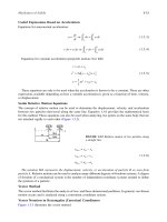
Figure 3-1 – Typical Section I Single PRV Installation
3.4
Figure 3-2 – Typical Section I Multiple PRV Installation
3.5
Figure 3-3 – Direct Spring Operated PRV with Lift Lever
3.7
Figure 3-4 – Pilot Operated PRV Field Test Assembly
3.7
Figure 3-5 – Safety Selector Valve
3.8
Figure 3-6 – Recommended ASME Section I Piping Arrangement
3.8
Figure 3-7 – Typical Section VIII Single Device Installation (Non-Fire) – Set at the MAWP of the Vessel
3.10
Figure 3-8 – Typical Section VIII Single Device Installation (Non-Fire) – Set below the MAWP of the Vessel
3.11
Figure 3-9 – Typical Section VIII Single Device Installation (Fire) – Set at the MAWP of the Vessel
3.12
Figure 3-10 – Typical Section VIII Multiple Valve (Non-Fire Case) Installation
3.13
Figure 3-11 – Typical Section VIII Multiple Valve (Fire Case) Installation
3.14
Figure 3-12 – Typical ASME Section VIII Nameplate
3.18
Figure 3-13 – Isolation Valve Requirements
3.20
Figure 3-14 – PRV Discharge Piping Example
3.21
Figure 3-15 – API 527 Leak Test for Gas Service
3.24
The following Tables are included in this chapter:
Page
Table 3-1 – Section I Set Pressure Tolerances
3.7
Table 3-2 – ASME Section VIII Set Pressure Tolerance
3.16
Table 3-3 – Design Basis for Sizing Downstream Piping
3.21
Table 3-4 – API 527 Leakage Rate Acceptance for Metal Seated PRV (Gas Service)
3.25
PVCMC-0296-US-1203 rev 1-2015 Copyright © 2012 Pentair plc. All rights reserved.
3.2
Pentair Pressure Relief Valve Engineering Handbook
Chapter 3 – Codes and Standards
Technical Publication No. TP-V300
I. Introduction
This section will provide highlights (please note this is not
a complete review) of several commonly used global
codes, standards and recommended practices that may
be referenced when selecting pressure relief valves. The
documents that are listed in this handbook are subject to
revision and the user should be aware that the following
information may not reflect the most current editions.
II. American Society of Mechanical Engineers
(ASME) Boiler and Pressure Vessel Code
There is information contained within various sections in
the Code that provide rules for design, fabrication, testing,
materials and certification of appurtenances, such as
pressure relief valves that are used in the new construction
of a boiler or pressure vessel. The scope of this handbook
will limit this discussion to the Section I and Section VIII
portion of the Code. The text is based upon the 2013
revision of the Code.
Section I – Rules for Construction of Power Boilers
Scope
The general requirements found in part PG of the Section I
Code provides rules that are applicable to the construction
of new boilers that generate steam at a pressure equal to
or more than 15 psig [1.03 barg]. In addition, these rules
will apply to the construction of new hot water boilers that
operate above 160 psig [11.0 barg] and/or when the
operating temperature exceeds 250°F [120°C]. For boilers
that operate outside of these parameters, the user may
wish to review Section IV of the Code that deals with rules
for heating boilers.
Acceptable Valve Designs
ASME Section I traditionally allowed only the use of direct
acting spring loaded pressure relief valves, but the use of
self-actuated pilot operated pressure relief valves is now
allowed. The use of power-actuated pressure relief valves
can be used in some circumstances for a forced-flow
steam generator. No other types of pressure relief valves or
non-closing devices such as rupture disks can be used for
this section of the Code.
Allowable Vessel Accumulation
One requirement in Section I is that the maximum
accumulation allowed during an overpressure event must be
limited to 3% when one pressure relief valve is used to
provide protection. There are specific rules listed in Section I
that will oftentimes require the use of two or more pressure
relief valves to provide protection. More details on these
multiple valve installation requirements are found in
Chapter 5 (USCS units) or Chapter 6 (Metric units) that deal
with sizing and selection. When multiple PRVs are used, the
allowable accumulation for a fired vessel can be 6%.
For a single PRV installation, the Code will allow the
highest set pressure to be equal to maximum allowable
working pressure (MAWP). Therefore, the design of this
valve must allow adequate lift to obtain the needed
capacity within 3% overpressure. Chapter 4 of the
handbook will discuss how the design of a Section I valve
provides this needed lift with minimal overpressure.
Although most users desire this highest possible set
pressure (equal to MAWP) to avoid unwanted cycles, the
Code does allow this PRV to be set below the MAWP.
For a multiple PRV installation, the Code will allow for a
staggered or variable set pressure regime for the valves.
This helps to avoid interaction between the safety valves
during their open and closing cycle. As noted above, the
accumulation rule allows for 6% rise in pressure above the
MAWP. One of the multiple valves, sometimes called the
primary pressure relief valve, must still be set no higher
than the MAWP but the additional or supplemental pressure
relief valve can be set up to a maximum of 3% above the
MAWP. In this case, the same valve design criteria,
obtaining the needed valve lift with 3% overpressure, is still
required. The Code requires that the overall range of set
pressures for a multiple valve installation not exceed 10%
of the highest set pressure PRV. Figures 3-1 and 3-2 help to
illustrate the single and multiple valve installation.
Pressure Relief Valve Certification Requirements
The ASME organization itself does not do the actual
inspection and acceptance of a pressure relief valve
design to meet the requirements of the Code. Traditionally,
it has been the National Board of Boiler and Pressure
Vessel Inspectors (National Board) that has been
designated by the ASME to perform this duty.
One test that is performed is to demonstrate that an
individual valve will provide the capacity of steam that is
expected when the valve is called upon to relieve. For
each combination of valve and orifice size, valve design
and set pressure, there are to be three valves tested to
measure their capacity. These capacity certification tests
are done with saturated steam at a flowing pressure using
the greater of 3% or 2 psi [0.138 bar] overpressure. The
requirement is that the measured capacity from any of the
three valves must fall within a plus or minus 5% of the
average capacity of the three valve test. If one valve were
to fail to meet this criteria, then rules in the Code allow for
two more valves to be tested. Now, all four valves must fall
within a plus or minus 5% of the average capacity of all
four valves now tested. If either of the two additional valves
fail to meet this range, then valve certification is denied.
When the valve capacity certification is approved, this
individual valve will be given a rated capacity that is 90%
of the average capacity found during the testing. It is this
rated capacity that is used to size and select valves per
the ASME Section I procedures in Chapters 5 and 6.
PVCMC-0296-US-1203 rev 1-2015 Copyright © 2012 Pentair plc. All rights reserved.
3.3
Pentair Pressure Relief Valve Engineering Handbook
Chapter 3 – Codes and Standards
Technical Publication No. TP-V300
PRV Specifications
Vessel Pressure %
Vessel Specifications
103
Accumulation
(3%)
Overpressure
(3%)
Set Pressure
Maximum
Accumulation
100
MAWP
Blowdown (4%)
Simmer Pressure
98
Reseat Pressure
96
Leak Test Pressure
93
90
Figure 3-1 – Typical Section I Single PRV Installation
PVCMC-0296-US-1203 rev 1-2015 Copyright © 2012 Pentair plc. All rights reserved.
3.4
Possible
Operating
Pressure
Pentair Pressure Relief Valve Engineering Handbook
Chapter 3 – Codes and Standards
Technical Publication No. TP-V300
Primary PRV
Specifications
Supplemental PRV
Specifications
Vessel Pressure %
106
Vessel
Specifications
Maximum
Accumulation
Supplemental PRV
Overpressure (3%)
Supplemental
PRV Set Pressure
Primary PRV
Overpressure (3%)
Accumulation
(6%)
Supplemental PRV
Blowdown (4%)
Simmer
Pressure
Primary PRV
Set Pressure
Primary PRV
Blowdown (4%)
103
101
100
Reseat
Pressure
Simmer
Pressure
MAWP
99
98
Leak Test
Pressure
97
Reseat Pressure
96
Leak Test
Pressure
93
90
Possible
Operating
Pressure
Figure 3-2 – Typical Section I Multiple PRV Installation
PVCMC-0296-US-1203 rev 1-2015 Copyright © 2012 Pentair plc. All rights reserved.
3.5
Pentair Pressure Relief Valve Engineering Handbook
Chapter 3 – Codes and Standards
Technical Publication No. TP-V300
This three valve test is normally used for a very narrow,
oftentimes non-standard, application. Please note that the
set pressure cannot vary in order to provide a code stamp
for the safety valve. If a safety valve will be used in multiple
applications that have different set pressures, then another
capacity certification test procedure can be used. A ratio
of the measured capacity over the flowing pressure (using
an overpressure of 3% or 2 psi [0.138 bar], whichever is
greater) is established with testing four valves of the same
connection and orifice size. These four valves are tested at
different set pressures that would be representative of their
expected application. This ratio is plotted to give a slope
that will determine the straight line relationship between the
capacity and the flowing pressure of the valve during relief.
All four valves tested must fall within plus or minus 5% of
the average straight line slope. If one valve were to fall
outside of this plus or minus 5% range, then two additional
valves can be tested. No more than four additional valves
can be tested or the certification will be denied.
When the valve capacity certification is approved then the
rated slope, used to size and select valves, is limited to
90% of the average slope measured during testing.
A third, and frequently used, capacity certification test is
available when the design of a safety valve encompasses
many different sizes and set pressure requirements. One
requirement for grouping different size safety valves as
one specific design family is that the ratio of the valve
bore diameter to the valve inlet diameter must not
exceed the range of 0.15 to 0.75 when the nozzle of the
valve controls the capacity. If the lift of the valve trim
parts controls the capacity, then the lift to nozzle
diameter (L/D) of the safety valves in the design family
must be the same.
Once the design family is determined, then three valve
sizes from the family and three valves for each size, for a
total of nine valves, are tested to measure their capacity
with steam. Once again, these flow tests are done with 3%
or 2 psi [0.138 bar], whichever is greater. These measured
values are compared to the expected theoretical capacity
delivered through an ideal nozzle or flow area where there
are no losses to reduce flow. A coefficient of discharge
(Kd) is denoted for each of the nine tests as follows:
Kd
=
Actual Flow
Theoretical Flow
Similar to the other two capacity tests above, each of the
nine values of Kd must fall within plus or minus 5% of the
average of the nine tests. If one valve falls outside of this
range then two more valves may be tested, up to a limit of
four total additional valves. When excluding the replaced
valves, the Kd of all valves tested must fall in the plus or
minus 5% of the overall average or the certification is
denied.
PVCMC-0296-US-1203 rev 1-2015 Copyright © 2012 Pentair plc. All rights reserved.
3.6
If the capacity certification test is successful, then the
rated coefficient of discharge (K) is established for the
valve design family. The K is equal to 90% of the Kd value.
In addition to establishing the rated capacities, the
certification testing will also require that the blowdown of
any Section I valve be demonstrated not to exceed 4%
when the certification set pressure is above 100 psig
[6.90 barg] or not to exceed 4 psi [0.276 bar] when the
certification set pressure is below 100 psig [6.90 barg].
If a pressure relief valve is to be used to protect an
economizer (see Figure 5-2 or 6-1) then this device must
be capacity certified on water as well as saturated steam.
The same set pressure tolerances and maximum
blowdown criteria that is required for steam as the test
media is also required for water as the test media.
The Code requires that the manufacturer demonstrate that
each individual pressure relief valve or valve design family
tested per the above requirements also provide similar
operational performance when built on the production
line. Therefore, every six years, two production valves are
chosen for each individual valve or valve design family for
set pressure, capacity, and blowdown testing. As with the
initial certification testing an ASME designated third party,
such as the National Board, is present to witness these
production valve tests.
Pressure Relief Valve Design Criteria
Each production PRV must have its set pressure
demonstrated with the valve being tested on steam. When
the testing equipment and valve configuration will allow, this
set pressure test is done by the manufacturer prior to
shipping. If the set pressure requirement is higher or the
test drum volume requirement is larger than the capabilities
that reside at the manufacturing facility, then the valve can
be sent to the site, mounted on the boiler and tested. This
in situ testing is rarely performed today due to safety
concerns and possible damage to the safety valve and
other equipment. The Code recognizes these concerns
and will allow the manufacturer to use two alternative
methods to demonstrate the set pressure on steam.
When there is limited capacity on the test stand, the rapid
opening of a steam safety valve will deplete the force
holding the seat in lift during testing. This can damage the
seating surfaces during the reclosure of the valve.
Therefore, one alternative method is to limit the lift of the
safety valve seat when tested. This can be done by
externally blocking the movement of the valve trim parts,
such as the spindle assembly shown in Figure 3-3, that
move upward when the safety valve opens. If this restricted
lift test is performed, the manufacturer must mechanically
confirm the actual required lift is met.
When the required set pressure exceeds the manufacturer’s
test boiler capabilities, another acceptable alternate test
Pentair Pressure Relief Valve Engineering Handbook
Chapter 3 – Codes and Standards
Technical Publication No. TP-V300
method is to use what is called a lift assist device. These
devices attach to the same spindle assembly discussed
above. The safety valve is subjected to the steam pressure
from the test boiler. Since the test boiler pressure is limited,
Lift Lever
Spindle Assembly
Since the test stand accumulators are of limited volume in a
valve manufacturing environment, there is no requirement
to measure the capacity of a production safety valve. The
initial certification and renewal testing of valve capacities
are discussed above.
A seat leakage test is required at the maximum expected
operating pressure, or at a pressure not exceeding the
reseat pressure of the valve. The requirement is that there is
to be no visible leakage.
Each production PRV will have its pressure containing
components either hydrostatically tested at 1.5 times the
design of the part or pneumatically tested at 1.25 times the
design of the part. This proof test is now required even for
non-cast pressure containing parts such as bar stock or
forgings where the test pressures could exceed 50% of
their allowable stress. A pressure containing part made in a
cast or welded form will always be proof tested no matter
what its allowable stress may be.
A Section I PRV with an inlet that is equal to or greater than
3" [80 mm] in size must have a flanged or welded inlet
connection. Any PRV with an inlet less than 3" [80 mm] can
have a screwed, flanged or welded connection.
Figure 3-3 – Direct Spring Operated PRV with Lift Lever
the lift assist device must have the ability to add upward
lifting force, typically via some hydraulically powered
system, to overcome the spring compression. The lift assist
device has instrumentation that can measure the upward
force being applied. Using the safety valve seat
dimensions and the operating pressure from the test boiler,
the set pressure can be determined with minimal lift of the
seat. As with the restricted lift test above, the manufacturer
must mechanically confirm the actual required lift is met.
A recent change in the Section I Code does not require a
demonstrated test of the valve blowdown for production
safety valves. For example, the typical blowdown setting for
a production Section I PRV is 4% for valves set above 375
psig [25.9 barg] and the valve adjustments are to be set
per manufacturer’s instructions to reflect this blowdown.
All pressure relief valves must have a device to check if
the trim parts are free to move when the valve is exposed
to a minimum of 75% of its set pressure. This device is
normally a lift lever (see Figure 3-3) for a direct spring
loaded or pilot operated valve. A pilot operated valve may
also use what is called a field test connection, where an
external pressure can be supplied to function the valve
(see Figure 3-4).
Active Process
Figure 3-4 – Pilot Operated PRV Field Test Assembly
Table 3-1 – Section I Set Pressure Tolerances
Set Pressure, psig [barg]
Less than or equal to 70 [4.82]
More than 70 [4.82] and equal to or less than 300 [20.7]
More than 300 [2.07] and equal to or less than 1000 [70.0]
More than 1000 [70.0]
Tolerance (plus or minus) from the set pressure
2 psi [0.137 bar]
3% of the set pressure
10 psi [0.690 bar]
1% of the set pressure
PVCMC-0296-US-1203 rev 1-2015 Copyright © 2012 Pentair plc. All rights reserved.
3.7
Pentair Pressure Relief Valve Engineering Handbook
Chapter 3 – Codes and Standards
Technical Publication No. TP-V300
Pressure Relief Valve Installation
There are specific maximum lengths of inlet piping
specified by ASME Section I that mandate a close
coupling of the safety valve to the vessel. The inlet and
outlet piping shall have at least the area of the respective
valve inlet or outlet area. If there are multiple valves
mounted on one connection, then this connection must
have an area at least as large as the two safety valves inlet
connection areas in total. These installation requirements
are extremely important for these safety valves that have
very minimal blowdown settings. There will be more on
this topic in Chapter 4.
There can be no intervening isolation valve between the
vessel and the safety valve. There also cannot be any
isolation valve downstream of the safety valve.
Flow
Valve
Position
Indicator
PRV
Connection
Bleed Port
for Standby
PRD
An exception to the mandate of no isolation valves for the
inlet connection of a Section I safety valve lies in what is
called an ASME Code Case. These code cases are not a
part of the main body of the document as they are a
vehicle to respond to inquiries asking for clarifications
or alternatives to the rules. These code cases may be
published as often as four times a year and their
implementation is immediate when there is latitude that
has been granted to modify a requirement. In some
instances, a code case will become a part of the Code in
some future revision.
Process Connection
Figure 3-5 – Safety Selector Valve
Fixed support anchored to
building structure
Seal Wire
Code Case 2254 allows the use of diverter, or changeover
valves, when the steam drum has a MAWP of 800 psig
[55.2 barg] or less. The Anderson Greenwood Safety
Selector Valve (see Figure 3-5) is a diverter valve that will
meet the requirements laid out in the code case. These
requirements include that the diverter valve never be in a
position where both safety valves could be blocked at the
same time, there must be a positive indication of the
active safety valve, vent valves to safely bleed pressure
for a newly isolated safety valve are to be provided, and
that a minimum flow coefficient (Cv) is met. With any code
case, the device, in this instance the diverter valve, must
be marked with the Code Case 2254 on the nameplate.
The discharge piping is also required to be short and
straight as possible and also designed to reduce stress
on the safety valve body. It is not uncommon to find the
outlet piping causing distortion of the valve body which in
turn causes the seat and nozzle to not properly align,
therefore causing leakage. The discharge piping should
also be designed to eliminate condensation and water to
gather in the discharge of the safety valve. Figure 3-6
illustrates an ideal installation with a short discharge
angled tailpipe that is inserted into, but not attached to,
an externally supported pipe riser.
Assemblers
There is wording in the Code that defines a manufacturer
as the entity that is responsible for meeting the design
PVCMC-0296-US-1203 rev 1-2015 Copyright © 2012 Pentair plc. All rights reserved.
3.8
Discharge
Pipe
“L”
as short
as possible
Drip Pan
Drain
Drain
Shortest Possible
Length, refer to
ASME Boiler Code
Section I, PG-71.2
NOTE:
Allow sufficient space
to prevent bottoming
or side binding of the
drip pan on the
discharge pipe under
maximum conditions
of expansion.
Recommended Minimum Diameter
1/2" Larger than Valve Inlet
Boiler Drum
Rounded Smooth Length
Figure 3-6 – Recommended ASME Section I
Piping Arrangement
Pentair Pressure Relief Valve Engineering Handbook
Chapter 3 – Codes and Standards
Technical Publication No. TP-V300
criteria to produce the valve components that can be put
together to build a valve that has been certified by the
testing requirements listed above. This approval by the
ASME designee to produce valves with a Code stamp
symbol is specific to the manufacturer’s physical location.
is greater. The valve model number, set pressure and inlet
size are also required fields for the nameplate.
To best serve the user community, the Code allows the
manufacturer to designate other locations that will
inventory valve components to efficiently build and test
pressure relief valves that mirror those produced at the
manufacturer’s location. These organizations are called
“assemblers,” and are allowed to assemble, adjust, test
and code stamp certified designs. They are required to
use OEM parts to assemble valves, and can only purchase
these parts direct from the manufacturer or another
certified assembler. The assembler is required to use the
same assembly and test procedures as the manufacturer
and is not allowed to machine or fabricate parts. An
assembler may be owned by the manufacturer, or be a
separate entity.
In addition to this nameplate identification, the PRV is
required to have all parts used in the adjustment of the set
pressure and blowdown to be sealed by the manufacturer
or assembler. This seal will carry the identification of
which authorized facility built and tested the PRV.
As with the manufacturer’s location, an assembler has
their quality system reviewed and approved by an ASME
designated third party, such as the National Board. The
assembler most likely will not be able to produce all of the
valves that are certified by the manufacturer per the Code
and they must define in detail what valve designs they
can assemble and what, if any limitations, there may be in
the actions taken to configure these valve designs to meet
the customer requirements.
As with the manufacturer, the Code requires that the
assembler demonstrate that each individual pressure relief
valve or valve design family where they are approved, be
tested. Therefore, every six years, two assembler built
valves are chosen for each individual valve or valve design
family and are sent in for set pressure, capacity, and valve
stability testing. As with the manufacturer production valve
testing, an ASME designated third party, such as the
National Board, is present to witness these production
valve tests.
This assembler program is strictly to be used to provide
new, not repaired, pressure relief valves.
Nameplates
All pressure relief valves built in accordance with ASME
Section I are required to have specific information
contained on a nameplate that is attached to the valve. The
manufacturer’s name along with the assembler’s name, if
applicable, is to be shown. The rated capacity is to be
shown in superheated steam for reheaters and
superheaters (see Figures 5-2 or 6-1), water and saturated
steam for economizers, and saturated steam for other
Section I locations. Recall that this rated capacity is 90% of
that measured during certification testing at a flowing
pressure at 3% overpressure or 2 psi [0.138 bar] whichever
You can identify a pressure relief valve that has been
certified to ASME Section I by locating a “V” marked on
the nameplate.
Section VIII – Rules for Construction of Pressure
Vessels
Scope
Division I of ASME Section VIII will provide rules for the
new construction of vessels which contain pressure that is
supplied via an external source or pressure generated by
heat input or a combination of both. Since the designs of
these vessels can be numerous, it may be easier to
provide examples of what type of pressure containers
might not be considered an ASME Section VIII vessel.
Some common examples can include the following:
• Vessels having an inside diameter or cross section
diagonal not exceeding 6" [152 mm] of any length at
any design pressure
• Vessels having a design pressure below 15 psig
[1.03 barg]
• Fired tubular heaters
• Components, such as pump casings or compressor
cylinders, of a moving mechanical piece of equipment
that are a part of the device and designed to meet the
working conditions of the device
• Piping systems that are required to transport gases or
liquids between areas
The reader should note that there may be local or country
statutes that determine whether or not a certain vessel is
to conform to the rules of ASME Section VIII.
The requirements for ASME Section VIII are less stringent
than those in Section I. It is permissible to use a PRV
certified for Section I in any Section VIII application
provided than the design will meet all of the requirements
of the application.
Acceptable Designs
As with ASME Section I, reclosing direct acting spring
loaded and reclosing self-actuated pilot operated pressure
relief valves can be used for Section VIII vessel protection.
Unlike Section I, this part of the Code allows the use of
non-reclosing devices such as rupture disks, non-closing
direct acting spring loaded valves, and pin devices where
the pin holds the pressure containing component closed.
PVCMC-0296-US-1203 rev 1-2015 Copyright © 2012 Pentair plc. All rights reserved.
3.9
Pentair Pressure Relief Valve Engineering Handbook
Chapter 3 – Codes and Standards
Technical Publication No. TP-V300
PRV Specifications
Vessel Pressure %
110
Overpressure
(10%)
Vessel Specifications
Maximum
Accumulation
Accumulation
(10%)
Set Pressure
100
Simmer Pressure
98
MAWP
Blowdown (8%)
Reseat Pressure
Leak Test Pressure
92
90
84
Possible
Operating
Pressure
Figure 3-7 – Typical Section VIII Single Device Installation (Non-Fire) – Set at the MAWP of the Vessel
PVCMC-0296-US-1203 rev 1-2015 Copyright © 2012 Pentair plc. All rights reserved.
3.10
Pentair Pressure Relief Valve Engineering Handbook
Chapter 3 – Codes and Standards
Technical Publication No. TP-V300
PRV Specifications
Vessel Pressure %
110
Vessel Specifications
Maximum
Accumulation
Accumulation
(10%)
Overpressure
(14%)
100
Set Pressure
96
Simmer Pressure
94
MAWP
Blowdown (8%)
Reseat Pressure
88
Leak Test Pressure
86
84
Possible
Operating
Pressure
Figure 3-8 – Typical Section VIII Single Device Installation (Non-Fire) – Set below the MAWP of the Vessel
PVCMC-0296-US-1203 rev 1-2015 Copyright © 2012 Pentair plc. All rights reserved.
3.11
Pentair Pressure Relief Valve Engineering Handbook
Chapter 3 – Codes and Standards
Technical Publication No. TP-V300
Primary PRV Specifications
Vessel Pressure %
121
Vessel Specifications
Maximum
Accumulation
Accumulation
(21%)
Overpressure
(21%)
Set Pressure
100
Simmer Pressure
98
MAWP
Blowdown (8%)
Reseat Pressure
92
Leak Test Pressure
90
84
Possible
Operating
Pressure
Figure 3-9 – Typical Section VIII Single Device Installation (Fire) – Set at the MAWP of the Vessel
PVCMC-0296-US-1203 rev 1-2015 Copyright © 2012 Pentair plc. All rights reserved.
3.12
Pentair Pressure Relief Valve Engineering Handbook
Chapter 3 – Codes and Standards
Technical Publication No. TP-V300
Primary PRV
Specifications
Supplemental PRV
Specifications
Vessel Pressure %
Vessel
Specifications
116
Maximum
Accumulation
Supplemental PRV
Overpressure (10%)
Accumulation
(16%)
Primary PRV
Overpressure
(16%)
Primary PRV
Set Pressure
Simmer Pressure
Supplemental PRV
Set Pressure
105
Simmer Pressure
103
Supplemental PRV
Blowdown (8%)
Primary PRV
Blowdown (8%)
100
MAWP
98
Reseat Pressure
97
Leak Test Pressure
95
Reseat Pressure
92
Leak Test
Pressure
90
80
Possible
Operating
Pressure
Figure 3-10 – Typical Section VIII Multiple Valve (Non-Fire Case) Installation
PVCMC-0296-US-1203 rev 1-2015 Copyright © 2012 Pentair plc. All rights reserved.
3.13
Pentair Pressure Relief Valve Engineering Handbook
Chapter 3 – Codes and Standards
Technical Publication No. TP-V300
Primary PRV
Specifications
Supplemental PRV
Specifications
Vessel Pressure %
121
Vessel
Specifications
Maximum
Accumulation
Supplemental PRV
Overpressure (10%)
Accumulation
(21%)
Primary PRV
Overpressure
(21%)
Supplemental PRV
Set Pressure
110
Simmer Pressure
108
Supplemental PRV
Blowdown (8%)
Primary PRV
Set Pressure
Simmer Pressure
Reseat Pressure
102
Leak Test
Pressure
100
MAWP
98
Primary PRV
Blowdown (8%)
Reseat Pressure
92
Leak Test
Pressure
90
80
Figure 3-11 – Typical Section VIII Multiple Valve (Fire Case) Installation
PVCMC-0296-US-1203 rev 1-2015 Copyright © 2012 Pentair plc. All rights reserved.
3.14
Possible
Operating
Pressure
Pentair Pressure Relief Valve Engineering Handbook
Chapter 3 – Codes and Standards
Technical Publication No. TP-V300
A combination of a non-reclosing device mounted in series
with a reclosing device can also be an acceptable relieving
system. There is also a choice to use simple openings that
flow or vent away excessive pressure.
Allowable Vessel Accumulation
There are different levels of accumulation that are
permissible for a Section VIII vessel. When the source of
overpressure is not being generated by an external fire
and there is one pressure relieving device to be used, the
vessel is allowed to experience an accumulation in
pressure, during an upset condition, up to 10% over the
maximum allowable working pressure (MAWP). Most users
desire the highest possible set pressure to avoid unwanted
PRV cycles. When a single pressure relieving device is
used, the maximum set or burst pressure allowed is
equal to the MAWP. In this case, the value of the vessel
accumulation and the device’s overpressure are the same
(see Figure 3-7). Therefore, the design of a pressure
relief valve must allow adequate lift to obtain the needed
capacity within 10% overpressure. Chapter 4 of the
handbook will discuss how the design of a Section VIII
valve provides this needed lift with minimal overpressure.
The Code does allow this pressure relief device to be set
below the MAWP. When the device is set to open below the
MAWP, it may be sized using the overpressure (the
difference between the set or burst pressure and the
maximum allowable accumulation) as shown in Figure 3-8.
When a pressure vessel can experience an external fire
that would cause an overpressure condition, the Code
allows for a maximum accumulation of 21%. The rule is
the same as the non-fire condition, in that the maximum
set or burst pressure for a single device installation cannot
be higher than the MAWP of the vessel. If a pressure relief
valve is selected, it typically will have the same operational
characteristics as the one selected for a non-fire relieving
case. An overpressure of 21% can be used to size this
valve. See Figure 3-9.
There is no mandate in Section VIII that requires the use of
multiple relieving devices. However, in some applications it
may be that the required capacity to be relieved is too
much for a single relieving device. If more than one device
is needed, the accumulation, for a non-fire generated
overpressure scenario, is to not exceed 16% above the
MAWP. This additional accumulation will allow for the
multiple pressure relief valves to be set at different
pressures. As mentioned previously, this staggered set
point regime will help to avoid interaction between the
multiple PRVs. Similar to Section I, the rules are that a
primary PRV can be set no higher than the MAWP of the
vessel. Any additional or supplemental PRV can be set
above the MAWP, but at a level no higher than 5% above
the MAWP. These multi-device rules in Section VIII will
oftentimes allow for the operating pressure to remain at the
same level as they would be with a single valve installation.
Figure 3-10 will illustrate this multiple PRV scenario. There is
no requirement that multiple valves be of the same size,
although this is often found to be the case in order to best
utilize the inventory of spare parts.
When multiple PRVs are required when the relieving case
contingency is heat input from an external source, such
as a fire, the primary valve can again be set no higher
than the MAWP. Any supplemental valve can be set to
open at a pressure 10% above the MAWP. The overall
vessel accumulation that is allowed by the Code is now
21%. Please note that if there are any non-fire case
contingencies that are to be handled with these multiple
valves, any supplemental valve set above 105% of the
MAWP cannot be counted in the available relieving
capacity. Figure 3-11 provides an example of multiple
PRVs for fire cases.
Pressure Relief Valve Certification Requirements
As we learned in the Section I certification discussion, there
are capacity certifications required by the Code for
specific valve designs or families. These capacity tests
are performed on saturated steam, air or another type of
gas such as nitrogen for safety and safety relief valve
designs used for compressible fluids. If the design is to
be used in steam and in any other non-steam vapor/ gas,
then at least one capacity test must be done with steam
with the remainder of the tests to be performed on the
non-steam vapor or gas. Any relief or safety relief valve
used for incompressible media must be capacity certified
on water. If the safety relief valve is to have certification on
both compressible and incompressible media, then
individual capacity tests with gas and with liquid are
required.
The steam, gas, or liquid capacity tests are performed
with 10% or 3 psi [0.207 bar] overpressure in most
instances. Using this flowing pressure criteria, the same
three capacity tests outlined above for Section I can be
incorporated.
• Specific valve design, size and set pressure testing
(3 valves minimum)
• Specific valve design and size using the slope method
(4 valves minimum)
• Valve design family using the coefficient of discharge
method (9 valves minimum)
The same requirement to meet no more than a plus or
minus 5% variance in every capacity test is mandated in
Section VIII. Once the specific valve design or family
testing meets this requirement, then the rated capacity is
taken as 90% of the values measured in the capacity
testing. It is this rated capacity that is used to size and
select valves per the ASME Section VIII procedures in
Chapters 5 and 6.
PVCMC-0296-US-1203 rev 1-2015 Copyright © 2012 Pentair plc. All rights reserved.
3.15