A STUDY OF POLYGONAL TURNING USING ATTACHMENT
Bạn đang xem bản rút gọn của tài liệu. Xem và tải ngay bản đầy đủ của tài liệu tại đây (866.27 KB, 4 trang )
Đặng Anh Tuấn
Tạp chí KHOA HỌC & CÔNG NGHỆ
139(09): 53 - 56
A STUDY OF POLYGONAL TURNING USING ATTACHMENT
Dang Anh Tuan*
College of Technology - TNU
SUMMARY
This paper presents a proposed method to produce parts with polygonal cross-section by turning.
Based on hypotrochoid curve construction, a mechanism which combines motions of workpieces
and cutting tool to machines polygons’sides is proposed. A numerical program has been
established to find the optimized parameters for polygon’s properties. The results showed that the
geometry character of parts which are manufactured from this method can enhanced machining
efficiency, compared to conventional machine.
Key word: Hypotrochoid curve, polygon, turning, machining efficiency
INTRODUCTION*
Polygonal surfaces are produced usually by
milling or grinding on conventional or CNC
multifunctional specialized machine tools[1].
Surfaces of such polygonal structures are
required to meet the dimensional accuracy,
shape
and
quality
conditions
in
assembly[1,2]. When milling or grinding
these structures, if the process area is small,
there will be problem of low efficient.
Polygonal turning is a new developed process
which allows non-circular forms to be
machined without interrupting the rotation of
workpiece (During the operation, workpiece
and cutters rotate withthe certain conditions)
[3]. Some investigations have been done with
tool-holder’s structure and the methods to
machine faces[1,3,4,5]. However, these
methods only produce polygons with even
edges – holder mount multiple cutters, each
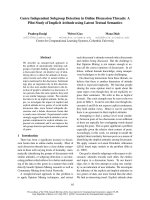
cutter form two oppositely sides. The paper
presents a method to machine parts with
polygonal cross-section by turning using
single cutter in holder based on hypotrochoid
curve construction.
distance d from the center of the interior
circle c2. Assign R01/R02 =n; the parametric
equationsfor the curve can be given by:
b
a
Tool
holder
__
Work piece
Cutter
Cutter’s
trajectory
Figure 1. A method to machine 6-side polygon (a)
and Tool-holder’s construction(b);
c1
THEORETICAL METHOD
In geometry, a hypotrochoidis a roulette
traced by point M attached to a circle c2of
radius R02 rolling around the inside of a fixed
circle c1 of radius R01, where the point is a
*
Tel: 0985 059022, Email:
x R01 R02 .cos d .cos n
(1.1)
y R01 R02 sin d .sin n
Where is the angle formed by the horizontal
53
Đặng Anh Tuấn
Tạp chí KHOA HỌC & CÔNG NGHỆ
and the center of the rolling circle.
With n integer, the shape of the region formed
inside the curve has is similar polygon. When
the distance between O2 and M changes, two
possible cases might be happened to the
region:
* Case 1 - WhenOM
to the construction method and the theory of
machining, this case is not suitable to be used.
* Case 2 - When OM>RO2 (Fig. 3b):the
shape of bounded region is similar as
polygon. However, at several moments, the
cutter may not involvein cutting process ( the
cutting point is out of workpiece boundary).
When raising the distance d between O2 and
M, polygon’s faces will be flatter butthe time
consumed in non-cutting stage is increases
(the region outside polygons will be bigger).
The percentage ratio of cutting time and total
time can be calculated as:
t
100.n.
(1.2)
%
(: the rotates angle in which the cutter
move half length of each face)
The convexity of faces can be determined as:
e
ln
l0
R01 R02 d
max O1M .cos
n
(1.3)
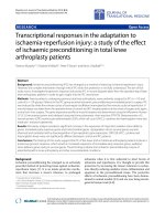
BUILDING THE MECHANISM
Figure 4 illustrates the mechanism with
holder driven by four-gear train connected to
(a)
139(09): 53 - 56
the spindle. In this setup, only onecutter is
mounted in holder. Distance R1 between
center of workpieces and holder can be
adjusted while the speed of cutter is
unchanged because of the fixed gearratio.
Distance R2 between cutter and center of
holder can also be changed. When workpiece
rotate and angle , cutter rotate an angle n
respectively.
Z2
Z3
n1
Z4
Z1
R1
Cutter
R2
Figure 4. Schematic diagram
The velocity of cutter also changes
corresponding to its position. When
workpiece is rotated at an angular speed of
rad/s (the same speed as spindle), velocity of
point cutter at point A in the trajectory (Fig.5)
can be determined as:
VA VA1 VA2
(1.4)
Where:
VA1 : Velocity of point A on workpiece;
VA1=.O1A
VA2 : Velocity of cutter;VA2=.n.R2
x: Angle between velocity vectors:
(b)
Figure 3. Hypotrochoid curve (n=3) when OM
54
Cutter's
trajectory
Đặng Anh Tuấn
Tạp chí KHOA HỌC & CÔNG NGHỆ
VA VA21 VA22 2.VA1.VA2 .cos x
y
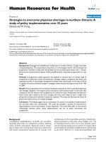
This velocity reaches the maximum value at
the middle points of sides and minimum at
edges of polygons (Fig.6c).
VA1
A
l
O1
x
With n is integer, polygon can be formed in
one rotation of spindle. However, through the
simulations, it was found that when n is
fraction, polygons formed by the mechanism
could be more precisely (Fig.6).
Figure 5. Velocity diagram at an abitrary point
x l (n 1)
(1.5)
From (1.4) and (1.5):
a)
90
b)
100
120
60
50
150
90
180
60
20
150
0
c)
40
120
30
(1.6)
. O1 A2 n2 .R22 2.n.O1 A.R2 .cos l (n 1)
O2
Velocity
VA
VA 2
139(09): 53 - 56
30
180
0
80
70
60
50
210
330
210
330
40
240
300
240
300
40
50
60
70
80
90
100
Angle
270
270
Figure 6. Illustrations of trajectory where n=5/2, R1=50, R2=22(a);
Polygon formed from trajectory(b); velocity-position graph on one side (c)
MATLAB programing is applied to determine the parameters with best properties for polygons.
Results from the calculation process showed in Table 1.
Table 1: Variation input and polygons’ properties formed:
Number
of edges
3
4
5
6
7
8
9
Input
variations
n
R1
R2
3
50
35
4
50
35
5
50
35
5/2
50
22
6
50
35
6/5
50
35
7
50
35
7/3
50
28
8
50
35
8/3
50
35
9
50
35
9/4
50
35
Non - cutting
time t (%)
25.97
13.72
9.78
19.78
7.71
5.61
6.42
9.03
5.47
4.90
13.90
4.16
Radiuslmax
36.42
23.35
19.73
34.57
18.09
16.71
17.20
24.41
16.63
16.32
31.47
15.96
Convexity
e (%)
-17.65
-9.16
6.00
0.10
-4.26
3.63
-3.22
0.02
-2.38
-0.52
-5.32
-0.02
Vmax
120.00
155.00
190.00
83.00
225.00
57.00
260.00
87.33
295.00
108.33
226.00
93.75
Vmin
110.43
151.87
188.27
79.20
223.86
56.90
259.18
86.47
294.39
108.01
222.32
93.55
55
Đặng Anh Tuấn
Tạp chí KHOA HỌC & CÔNG NGHỆ
SUMMARY AND CONCLUSIONS
The method prove that we can use
conventional lathe to machine polygons
satisfy the geometry variations and flatness
tolerance requirements. In the present work,
we can see the effect of input parameters (R1,
R2, n) to the properties of the polygons
(geometry variations, flatness tolerance,
convexity):
- Raising R2 make the polygons more flatter,
however the non-cutting time increases, and
the holder must have higher stiffness because
of cantilever structures.
- Depend on the ratio n of gear train, the
mechanism can make polygons with more
than 20 edges.
- Dimensions R1 and R2 can exceeded to
increase the size of polygon to meet the
geometry requirement.
The mechanism machines all faces at the
same time, overcome the shortcoming of
ordinary machining that need indexing and
long working hours. Parts with such
polygonal structure as hexagon-bolt heads,
nuts, or wooden furniture… can be
manufactured by this method instead of
milling or planning to improved the time
139(09): 53 - 56
efficiency. To process longer bars with
unchanged cross-section, the spline will be
mounted in holder’s shaft to maintain cutter’s
speed whilst cutter cuts along z-axis of
workpiece. This structure will be described in
further study.
REFERENCES
1. Wachter, K. (1987). Konstruktionslehre fur
Maschineningenieure (Engineering design for
machine engineers), VEB Verlag Technik, ISBN
3-341-00045-3.
2. Chen, D.; Lu, B. & Deng, X. (2009). Simulation
and experiment of milling isometric polygonal
profile based on NC method, 2nd IEEE
International Conference on Computer Science
and Information Technology, ICCSIT 2009, pp.
537-541, ISBN: 978-1-4244-4519-6.
3. Adrian Lucian, George Predincea, Nicolae.
Possibilities of processing polygonal surfaces on
CNC lathes,Annals of DAAAM & Proceedings,
ISSN: 1726-9679
4. Ghita, E. (2001),Teoria si tehnologia
suprafetelor poliforme (Theory and technology of
polyform sufaces), Editura BREN, ISBN 9738141-07-1.
5. Masala, I.; Predincea, N.; Ghionea, A. & Aurite.
Polygonal surface generating kinematics by
milling, Constructia de Masini, Year XLVII, No.
3, ISSN 0573-7419.
TÓM TẮT
NGHIÊN CỨU PHƯƠNG PHÁP GIA CÔNG ĐA DIỆN ĐỀU TRÊN MÁY TIỆN
Đặng Anh Tuấn*
Trường Đại học Kỹ thuật Công nghiệp – ĐH Thái Nguyên
Bài báo nghiên cứu về một phương pháp tiện các chi tiết có tiết diện dạng đa diện đều. Trên cơ sở
tạo hình của đường cong hypotrochoid, một bộ cơ cấu được sử dụng cho phép kết hợp các chuyển
động giữa phôi và dao trên máy tiện để gia công các mặt đồng thời. Kết quả từ chương trình mô
phỏng cho thấy một số ưu điểm của phương pháp gia công này (thông số hình học, hiệu suất gia
công) và khả năng mở rộng giới hạn về số cạnh đa diện so với các phương pháp cũ.
Từ khóa: Đường cong Hypotrochoid, đa diện đều, tiện, hiệu suất gia công
Ngày nhận bài:20/6/2015; Ngày phản biện:06/7/2015; Ngày duyệt đăng: 30/7/2015
Phản biện khoa học: PGS.TS Nguyễn Văn Dự - Trường Đại học Kỹ thuật Công nghiệp - ĐHTN
*
Tel: 0985 059022, Email:
56