Testing-overcurrent-protection (50+51+67)-Chris Werstiuk _ Cẩm Nang Dành Cho Kỷ Sư Thí Nghiệm RELAY
Bạn đang xem bản rút gọn của tài liệu. Xem và tải ngay bản đầy đủ của tài liệu tại đây (943.16 KB, 63 trang )
The Relay Testing Handbook
Testing Overcurrent Protection (50/51/67)
Chris Werstiuk
Professional Engineer
Journeyman Power System Electrician
Electrical Engineering Technologist
THE RELAY TESTING HANDBOOK:
Testing Overcurrent Protection (50/51/67)
THE RELAY TESTING HANDBOOK:
Testing Overcurrent Protection (50/51/67)
Chris Werstiuk
Professional Engineer
Journeyman Power System Electrician
Electrical Technologist
Valence Electrical Training Services
7450 w. 52nd Ave, M330
Arvada, CO 80002
www.relaytesting.net
Although the author and publisher have exhaustively researched all sources to ensure the
accuracy and completeness of the information contained in this book, neither the authors nor
the publisher nor anyone else associated with this publication, shall be liable for any loss,
damage, or liability directly or indirectly caused or alleged to be caused by this book. The
material contained herein is not intended to provide specific advice or recommendations for
any specific situation.
Trademark notice product or corporate names may be trademarks or registered trademarks
and are used only for identification, an explanation without intent to infringe.
The Relay Testing Handbook: Testing Overcurrent Protection (50/51/67)
First Edition
ISBN: 978-1-934348-12-3
Published By:
Valence Electrical Training Services
7450 w. 52nd Ave, M330, Arvada, CO, 80002, U.S.A.
Telephone: 303-250-8257
Distributed By:
www.relaytesting.net
Edited by:
One-on-One Book Production, West Hills, CA
Cover Art:
© James Steidl. Image from BigStockPhoto.com
Copyright © 2010 by Valence Electrical Training Services. All rights reserved.
Neither this book nor any part may be reproduced or transmitted in any form or by any
means, electronic or mechanical, including photocopying, microfilming, and recording, or by
any information storage and retrieval system, without permission in writing from the
publisher.
Published in the United States of America
Author’s Note
The Relay Testing Handbook was created for relay technicians from all backgrounds and provides the
knowledge necessary to test most of the modern protective relays installed over a wide variety of
industries. Basic electrical fundamentals, detailed descriptions of protective elements, and generic test
plans are combined with examples from real life applications to increase your confidence in any relay
testing situation. A wide variety of relay manufacturers and models are used in the examples to help
you realize that once you conquer the sometimes confusing and frustrating man-machine interfaces
created by the different manufacturers, all digital relays use the same basic fundamentals; and most
relays can be tested by applying these fundamentals.
This package provides a step-by-step procedure for testing the most common overcurrent protection
applications: Instantaneous Overcurrent (50), Time Overcurrent (51), and Directional Overcurrent
(67). Each chapter follows a logical progression to help understand why overcurrent protection is
used and how it is applied. Testing procedures are described in detail to ensure that the overcurrent
protection has been correctly applied. Each chapter uses the following outline to best describe the
element and the test procedures.
1.
2.
3.
4.
5.
Application
Settings
Pickup Testing
Timing Tests
Tips and Tricks to Overcome Common Obstacles
Real world examples are used to describe each test with detailed instructions to determine what test
parameters to use and how to determine if the results are acceptable.
Thank you for your support with this project, and I hope you find this and future additions of The
Relay Testing Handbook to be useful.
i
ii
Acknowledgments
This book would not be possible without support from these fine people
David Magnan, Project Manager
PCA Valence Engineering Technologies Ltd.
www.pcavalence.com
Ken Gibbs, C.E.T.
PCA Valence Engineering Technologies Ltd.
www.pcavalence.com
Les Warner C.E.T.
PCA Valence Engineering Technologies Ltd.
www.pcavalence.com
John Hodson : Field Service Manager
ARX Engineering a division Magna IV Engineering Calgary Ltd.
Do it right the first time
www.esps.ca www.avatt.ca www.vamp.fi
Robert Davis, CET PSE
Northern Alberta Institute of Technology
GET IN GO FAR
www.nait.ca
Lina Dennison
My mean and picky wife who
Made this a better book
Roger Grylls, CET
Magna IV Engineering
Superior Client Service. Practical Solutions
www.magnaiv.com
iii
iv
Table of Contents
Chapter 1 – Instantaneous Overcurrent (50) Protection
1.
2.
Application....................................................................................................................... 1
Settings ............................................................................................................................. 4
A) Enable Setting.......................................................................................................................................4
B) Pickup...................................................................................................................................................4
C) Time Delay ...........................................................................................................................................4
3.
Pickup Testing................................................................................................................. 4
A)
B)
C)
D)
Test Set Connections ............................................................................................................................5
Pickup Test Procedure if Pickup is Less Than 10 Amps ......................................................................8
Pickup Test Procedure if Pickup is Greater Than 10 Amps .................................................................8
Avoid Setting Changes and Interference Test Procedure .....................................................................9
4.
Timing Tests .................................................................................................................. 10
5.
6.
Residual Neutral Instantaneous Overcurrent Protection ......................................... 12
Tips and Tricks to Overcome Common Obstacles .................................................... 12
A) Timing Test Procedure .......................................................................................................................11
Chapter 2 – Time Overcurrent (51) Element Testing
1.
2.
Application..................................................................................................................... 15
Settings ........................................................................................................................... 18
A)
B)
C)
D)
E)
3.
Enable Setting.....................................................................................................................................18
Pickup.................................................................................................................................................18
Curve ..................................................................................................................................................18
Time Dial/Multiplier...........................................................................................................................18
Reset ...................................................................................................................................................18
Pickup Testing............................................................................................................... 19
A) Test Set Connections ..........................................................................................................................19
B) Pickup Test Procedure ........................................................................................................................22
4.
Timing Tests .................................................................................................................. 24
A)
B)
C)
D)
Using Formulas to Determine Time Delay.........................................................................................25
Using Graphs to Determine Time Delay ............................................................................................26
Using Tables to Determine Time Delay .............................................................................................28
Timing Test Procedure .......................................................................................................................29
5.
Reset Tests ..................................................................................................................... 29
6.
7.
Residual Neutral Time Overcurrent Protection ........................................................ 29
Tips and Tricks to Overcome Common Obstacles .................................................... 30
A) Reset Test Procedure ..........................................................................................................................29
v
Table of Contents (Cont.)
Chapter 3 – Directional Overcurrent (67) Element Testing
1.
Application..................................................................................................................... 31
A) Parallel Feeders.................................................................................................................................. 32
B) Transmission Line Ground Protection ............................................................................................... 34
C) Power Flow........................................................................................................................................ 34
2.
3.
Operation ....................................................................................................................... 35
Settings ........................................................................................................................... 36
A)
B)
C)
D)
E)
F)
G)
H)
I)
J)
K)
L)
M)
N)
4.
Enable Setting.................................................................................................................................... 36
Pickup ................................................................................................................................................ 36
Curve ................................................................................................................................................. 36
Time Dial/Multiplier.......................................................................................................................... 36
Reset .................................................................................................................................................. 36
Phase Directional MTA (Maximum Torque Angle).......................................................................... 37
Phase Directional Relays ................................................................................................................... 37
Minimum Polarizing Voltage ............................................................................................................ 37
Block OC When Voltage Memory Expires ....................................................................................... 37
Directional Signal Source .................................................................................................................. 37
Directional Block............................................................................................................................... 37
Directional Target.............................................................................................................................. 37
Directional Events ............................................................................................................................. 37
Directional Order ............................................................................................................................... 38
Pickup Testing............................................................................................................... 38
A) Test Set Connections ......................................................................................................................... 41
B) Determine Maximum Torque Angle in GE Relays............................................................................ 42
C) Quick and Easy Directional Overcurrent Test Procedures................................................................. 43
5.
6.
Timing Test Procedures ............................................................................................... 45
Tips and Tricks to Overcome Common Obstacles .................................................... 45
vi
Table of Figures
Figure 1: Ground Fault Protection Single-Line-Drawing.......................................................................................2
Figure 2: Ground Protection TCC ..........................................................................................................................2
Figure 3: 50/51 TCC #1..........................................................................................................................................3
Figure 4: 50/51 TCC #2..........................................................................................................................................3
Figure 5: 50/51 TCC #3..........................................................................................................................................3
Figure 6: 50/51 TCC #4..........................................................................................................................................3
Figure 7: Simple Instantaneous Overcurrent Connections .....................................................................................6
Figure 8: High Current Connections #1..................................................................................................................6
Figure 9: High Current Connections #2..................................................................................................................7
Figure 10: Neutral or Residual Ground Bypass Connection ..................................................................................7
Figure 11: Neutral or Residual Ground Bypass Connection Via Ø-Ø Connection ................................................7
Figure 12: Pickup Test Graph.................................................................................................................................8
Figure 13: Pickup Test Graph - Jogging.................................................................................................................9
Figure 14: 50-Element Timing Test .....................................................................................................................10
Figure 15: GE D-60 Relay Overcurrent Technical Specifications .......................................................................10
Figure 16: GE D-60 Relay Output Contact Technical Specifications ..................................................................11
Figure 17: Manta Test Systems M-1710 Technical Specifications ......................................................................11
Figure 18: 50-Element Minimum Pickup .............................................................................................................11
Figure 19: 50-Element Alternate Relay Connection.............................................................................................12
Figure 20: 51-Element North American Curves...................................................................................................16
Figure 21: 51-Element IEC European Curves ......................................................................................................16
Figure 22: ANSI Extremely Inverse with Different Pickup Settings....................................................................17
Figure 23: ANSI Extremely Inverse with Different Timing Settings...................................................................17
Figure 24: Simple Time Overcurrent Connections...............................................................................................20
Figure 25: High Current Connections #1..............................................................................................................20
Figure 26: High Current Connections #2..............................................................................................................21
Figure 27: Neutral or Residual Ground Bypass Connection ................................................................................21
Figure 28: Neutral or Residual Ground Bypass Connection Via Ø-Ø Connection ..............................................21
Figure 29: Pickup Test Graph...............................................................................................................................22
Figure 30: SEL-311C 51 Time Overcurrent Specifications .................................................................................23
Figure 31: 51-Element North American Curves...................................................................................................24
Figure 32: 51-Element Timing Test .....................................................................................................................24
Figure 33: 51-Element SEL-311C Timing Curve Characteristic Formulas..........................................................25
Figure 34: 51-Element Example Time Coordination Curve.................................................................................27
Figure 35: 51-Element Time Delay Calculation with Table.................................................................................28
Figure 36: 51-Element Timing for GE D-60 ........................................................................................................28
Figure 37: 51-Element Alternate Relay Connection.............................................................................................30
Figure 38: Parallel Transmission Lines with Standard Overcurrent Protection ...................................................32
Figure 39: Parallel Transmission Lines with Directional Overcurrent Protection................................................33
Figure 40: Directional Ground Overcurrent Protection for Transmission Lines ..................................................34
Figure 41: Directional Overcurrent Protection in an Industrial Application ........................................................34
Figure 42: Standard Phasor Diagram....................................................................................................................35
Figure 43: Directional Polarizing .........................................................................................................................35
Figure 44: Directional Polarizing .........................................................................................................................39
Figure 45: Typical Directional Polarizing using SEL Relays...............................................................................40
Figure 46: Directional Polarizing Using GE Relays and a 60º MTA Setting .......................................................40
Figure 47: 3-Line Drawing for Example Test Set Connection .............................................................................41
Figure 48: Directional Overcurrent Test Set Connections....................................................................................41
Figure 49: Normal Phasors...................................................................................................................................42
Figure 50: Phase A Characteristic Phasor ............................................................................................................42
vii
Chapter 1: Instantaneous Overcurrent (50) Protection
Chapter 1
Instantaneous Overcurrent (50) Element Testing
1. Application
Although the official designation of the 50 element is “instantaneous overcurrent,” a time delay
is often added to transform it into a definite-time overcurrent element. A 50-element will operate
if the current is greater than the pick-up setpoint for longer than the time delay setting. When the
instantaneous overcurrent element is used for phase overcurrent protection, it is labeled with the
standard IEEE designation “50.” Ground or neutral instantaneous overcurrent elements can have
the designations 50N or 50G depending on the relay manufacturer and/or relay model.
The 50-element can be used independently or in conjunction with time overcurrent (51)
functions. When used in a grounding scheme, typically all feeders have identical pick-up and
time delay settings. The main breaker would have a slightly higher setting and/or longer time
delay to ensure that a ground fault on a feeder will be isolated by the feeder breaker before the
main breaker operates. An example 50-element ground protection scheme is shown in the
following figures.
The 50-element protective curve looks like an “L” on a Time Coordination Curve (TCC, see
previous packages of The Relay Testing Handbook for details). The element will operate if the
current is on the right side of the vertical line for longer than the time indicated by the horizontal
line of the protective curve in Figure 2. In this example, a feeder ground fault greater than 10
Amps must last longer than one second before the 50-element will operate. The main breaker
protection will operate if any ground fault is greater than 15 Amps for longer than two seconds
www.RelayTesting.net
1
The Relay Testing Handbook: Testing Overcurrent Protection (50/51/67)
Time Co-ordination Curve
10.00
MAIN
Main Ground
Protection
PCB2
Time in seconds
50G
PCB3
1.00
Feeder Ground Protection
50G
50G
Current in amperes
100
FEEDER 1
FEEDER 2
Figure 1: Ground Fault Protection
Single-Line-Drawing
10
1
0.10
Figure 2: Ground Protection TCC
The 50-element can also be applied in conjunction with inverse-time overcurrent elements to
better protect equipment during high-current faults. The amount of damage created during a fault
can be directly related to the amount and duration of fault current. To limit equipment damage,
the relay should operate faster during high fault currents.
The following figures display how the 50-element can enhance equipment protection as well as
coordination with other devices. In Figure 3, the time overcurrent (51) relay curve intersects the
cable damage curve and, therefore, does not provide 100% protection for the cable. The cable is
only 100% protected if its damage curve is completely above the protection curve. Adding a 50element to the time overcurrent element will provide 100% cable protection as shown in Figure
4. However, the addition of the 50-element creates a mis-coordination between the R2 relay and
downstream Fuse 1 because the two curves now cross. The relay will operate before the fuse
when the relay curve is below and to the left of the fuse curve. This problem can be solved by
adding a slight time delay of 0.03 seconds, which will coordinate with the downstream fuse as
shown in Figure 5.
If we wanted to provide the best protection for the cable and fully utilize the available options of
most relays, we could add a second 50-element with no intentional time delay set with a pickup
setting higher than the maximum fuse current. This is shown in Figure 6. Adding another 50element will cause the relay to trip sooner at higher currents and will hopefully reduce the
amount of damage caused by fault.
2
Copyright©2010: Valence Electrical Training Services
Chapter 1: Instantaneous Overcurrent (50) Protection
Time Co-ordination Curve
Time Co-ordination Curve
10.00
10.00
Cable Damage Curve
Cable Damage Curve
R2 Time Overcurrent
Relay Curve
1.00
Mis-Coordination
PCB2
R2
Time in seconds
0.10
1.00
PCB2
R2 Instantaneous
Relay Curve
R2
CABLE 2
0.10
FUSE 1
CABLE 2
Fuse 1
Operating Curve
FUSE 1
Mis-Coordination
Fuse 1
Operating Curve
100,000
1,000
10,000
100,000
0.01
1,000
0.01
10,000
Time in seconds
R2 Time Overcurrent
Relay Curve
Current in amperes
Current in amperes
Figure 3: 50/51 TCC #1
Figure 4: 50/51 TCC #2
Time Co-ordination Curve
Time Co-ordination Curve
10.00
10.00
Cable Damage Curve
Cable Damage Curve
R2 Time Overcurrent
Relay Curve
R2 Time Overcurrent
Relay Curve
PCB2
R2 Instantaneous
Relay Curve
R2
CABLE 2
0.10
Time in seconds
Time in seconds
PCB2
1.00
1.00
R2 Instantaneous
Relay Curve #1
R2
CABLE 2
0.10
FUSE 1
FUSE 1
Fuse 1
Operating Curve
Fuse 1
Operating Curve
R2 Instantaneous
Relay Curve #2
Figure 5: 50/51 TCC #3
100,000
10,000
1,000
1,000
Current in amperes
100,000
0.01
10,000
0.01
Current in amperes
Figure 6: 50/51 TCC #4
50-elements can also be used to determine if the downstream equipment is operating and/or the
circuit breaker or motor starter is closed. When used in this fashion, the 50-element is set very
low, at some level below the minimum expected operating current. If the current flow exceeds
the 50-element setpoint, the circuit breaker is considered closed because there would be no
current flow if the circuit breaker was open. This method of breaker status indication will also
detect flashovers or insulation breakdown inside the circuit breaker that would not be detected by
a 52a or b contact and is often used in breaker failure (50BF) or inadvertent energization (50/27)
protection.
www.RelayTesting.net
3
The Relay Testing Handbook: Testing Overcurrent Protection (50/51/67)
2. Settings
The most common settings used in 50-elements are explained below:
A) Enable Setting
Many relays allow the user to enable or disable settings. Make sure that the element is ON or
the relay may prevent you from entering settings. If the element is not used, the setting should
be disabled or OFF to prevent confusion.
B) Pickup
This setting determines when the relay will start timing. Different relay models use different
methods to set the actual pickup and the most common methods are:
¾ Secondary Amps – the simplest unit. Pickup Amps = Setting
¾ Per Unit (P.U.) – This method can only exist if the relay settings include nominal current,
watts, or VA. This setting could be a multiple of the nominal current as defined or
calculated. If no such setting exists, it could be a multiple of the nominal CT (5A)
secondary or a multiple of the 51-element pickup setting.
Pickup
Pickup
Pickup
Pickup
Pickup
=
=
=
=
=
Setting
Setting
Setting
Setting
Setting
x
x
x
x
x
Nominal Amps, OR
Watts / (nominal voltage x √3 x power factor) OR
VA / (nominal voltage x √3), OR
CT secondary (typically 5 Amps)
51-Element Pickup
¾ Primary Amps – There must be a setting for CT ratio if this setting style exists. Check
the CT ratio from the drawings to make sure that the drawing match the settings.
Pickup = Setting / CT Ratio, OR
Pickup = Setting * CT secondary / CT primary
C) Time Delay
The time delay setting for the 50-element is a fixed-time delay that determines how long the
relay will wait to trip after the pickup has been detected. This setting is set in cycles, milliseconds, or seconds.
3. Pickup Testing
Instantaneous overcurrent testing is theoretically simple. Apply a current into the appropriate
input and increase it until you observe pickup indication. However, the actual application can be
frustrating and require some imagination. High currents are usually involved and the relay could
be damaged during testing. Most protective relay current inputs are rated for a maximum of 10
continuous Amps. Any input current greater than 10 Amps must be applied for the minimum
amount of time possible to prevent damage. It’s not a good feeling when you apply too much
current for too long and get that slight smell of burning insulation, quickly followed by smoke
billowing from the relay.
Instantaneous elements often interfere with time-overcurrent (51) testing and many relay testers
turn the 50-element off during 51-element testing. This practice may be required by the testing
specification but is NOT recommended when testing micro-processor relays. If the 50-element is
disabled, it MUST be tested AFTER the 51-element tests are complete and the 50-element has
been enabled. The opposite problem could occur because the 51-element function can interfere
with the instantaneous pickup tests. Do NOT turn off the time-overcurrent (51) element to
determine instantaneous pickup.
4
Copyright©2010: Valence Electrical Training Services
Chapter 1: Instantaneous Overcurrent (50) Protection
Before you begin testing, write down the pickup and time settings, and then calculate the pickup
current. Make sure that you know which unit is used. Some relays use secondary Amps for timeovercurrent (51) and multiples of that pickup for 50-elements. Use the formulas described in the
“Settings” section of this chapter to determine what the pickup actually is.
Now that you have determined the pickup and time delay settings, convert the current to primary
values using the following formulas:
¾ Primary Current = Secondary pickup current * CT ratio, OR
¾ Primary Current = Secondary Pickup current * CT Primary / CT Secondary.
It is extremely unlikely that you will find a microprocessor relay out of calibration. We perform
these tests to check relay operation, verify the settings have been correctly interpreted by the
design engineer, and that the settings were entered into the relay correctly. Check the primary
values and time delays against the coordination study and make sure they match. Make sure the
supplied TCC curves are at the correct voltage levels as discussed in previous packages of The
Relay Testing Handbook. Use the voltage conversions discussed in those packages if necessary.
If you do not have the coordination study, quickly check that the upstream 50-element setting is
higher and the downstream 50-element setting is lower than the relay under test.
The interrupting device (circuit breaker, etc…) must be rated to operate at the 50-element pickup
level or it may not be able to clear the fault once a trip signal is initiated. Check the interrupting
rating of the switchgear and circuit breaker or other disconnecting means. Make sure the
equipment interrupting rating is greater than the setting.
Look in the short circuit study and determine the maximum fault level at the switchgear. The
maximum fault level should be higher than the 50-element setpoint. If it’s not, question the
setting because the 50-element will likely never operate because there is not enough fault current
available. If no coordination study is provided, look at the next upstream transformer and use the
following formula to determine the maximum fault current that could flow through the
transformer. The setting should be less than this value.
Maximum Fault Current = Transformer VA / (System Voltage * %Z)
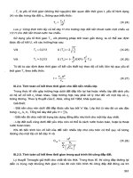
A) Test Set Connections
Because of the high currents involved with 50-element testing, you may need to try some of
the alternative test set connections shown below. Some technicians carry an older test-set
when their modern test sets are unable to reach the 50-element test levels.
You can prove the element is applied correctly by temporarily lowering the setting, but only
use this method as a last resort. In the past, there have been some relay models that did not
operate when secondary currents exceeded 100 A although the relay allowed settings larger
than 100A. If the testers who discovered this had not tested at the higher fault current levels,
it would never have been discovered.
www.RelayTesting.net
5
The Relay Testing Handbook: Testing Overcurrent Protection (50/51/67)
Residual ground (externally connected or internally calculated) and negative sequence
elements often interfere with 50-element tests. This problem can be overcome as shown in the
following figures if your test set is powerful or flexible enough. There will be some instances
where the residual and negative sequence setting will have to be disabled but, disabling
settings is a last resort and should only be undertaken if all other possibilities have been
exhausted. All disabled elements must be tested AFTER the instantaneous element tests have
been performed.
Connections are shown for AØ related tests. Simply rotate connections or test set settings to
perform BØ and CØ related tests. Simple phasor diagrams are shown above each connection
to help you visualize the actual input currents.
If your test set experiences problems during the test, even though the output is within its
theoretical capabilities, you may need to connect two or more test leads in parallel for the
phase AND neutral connections to lower the lead resistance. If this doesn’t work, try
connecting directly to the relay terminals as the circuit impedance may be more than your test
set can handle.
RELAY
RELAY TEST SET
A Phase Amps
Phase Angle
A Phase Amps
AØ Test Amps
0°
B Phase Amps
0A
C Phase Amps
0A
+
+
B Phase Amps
-120° (240°)
+
+
+
120°
Alternate Timer Connection
DC Supply +
+
C Phase Amps
Element
Output
Magnitude
+
+
Timer
Input
-
Element
Output
+
Timer
Input
Figure 7: Simple Instantaneous Overcurrent Connections
RELAY INPUT
TS#1
PU/2
RELAY
TS#2
PU/2
RELAY TEST SET
A Phase Input = Pickup
Magnitude
A Phase Amps
+
+
AØ Test Amps / 2
0°
B Phase Amps
AØ Test Amps / 2
0°
C Phase Amps
0A
+
C Phase Amps
Element
Output
A Phase Amps
+
B Phase Amps
+
Phase Angle
+
+
120°
Alternate Timer Connection
DC Supply +
+
Timer
Input
Element
Output
+
Timer
Input
Figure 8: High Current Connections #1
6
Copyright©2010: Valence Electrical Training Services
Chapter 1: Instantaneous Overcurrent (50) Protection
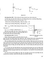
RELAY INPUT
AØ
PU/3
BØ
PU/3
CØ
PU/3
RELAY
RELAY TEST SET
A Phase Input = Pickup
Magnitude
A Phase Amps
A Phase Amps
AØ Test Amps / 3
0°
B Phase Amps
AØ Test Amps / 3
0°
C Phase Amps
AØ Test Amps / 3
0°
+
+
B Phase Amps
+
+
+
Alternate Timer Connection
DC Supply +
+
C Phase Amps
Element
Output
Phase Angle
+
+
Timer
Input
-
Element
Output
+
Timer
Input
Figure 9: High Current Connections #2
RELAY INPUT
TS#1
PU
TS#3
5%
5%
RELAY TEST SET
Neutral or Residual
Ground Amps = 0
B Phase Amps
C Phase Amps
A Phase Amps
AØ Test Amps
B Phase Amps
95% x AØ Test Amps
-120°
C Phase Amps
95% x AØ Test Amps
120°
0°
+
+
+
+
+
Element
Output
Phase Angle
+
Alternate Timer Connection
DC Supply +
A Phase Amps
Magnitude
+
+
Timer
Input
-
Element
Output
+
Timer
Input
Figure 10: Neutral or Residual Ground Bypass Connection
RELAY INPUT
BØ
PU
RELAY
AØ
PU
RELAY TEST SET
A OR B Phase Input=Pickup
+
+
0°
Test Hz
B Phase Amps
BØ Test Amps
-180°
Test Hz
C Phase Amps
0 Amps
120°
Test Hz
+
C Phase Amps
Element
Output
Frequency
AØ Test Amps
+
B Phase Amps
+
Phase Angle
A Phase Amps
+
A Phase Amps
+
Alternate Timer Connection
DC Supply +
+
Magnitude
Timer
Input
Element
Output
+
Timer
Input
Figure 11: Neutral or Residual Ground Bypass Connection Via Ø-Ø Connection
www.RelayTesting.net
7
The Relay Testing Handbook: Testing Overcurrent Protection (50/51/67)
B) Pickup Test Procedure if Pickup is Less Than 10 Amps
Use the following steps to perform a pickup test if the setting is less than 10 secondary Amps:
¾ Determine how you will monitor pickup and set the relay accordingly, if required. (Pickup
indication by LED, output contact, front panel display, etc…see previous packages of The
Relay Testing Handbook for details)
¾ Set the fault current 5% higher than the pickup setting. For example, 8.40 Amps for an
element with an 8.00 Amp setpoint. Make sure pickup indication operates.
¾ Slowly lower the current until the pickup indication is off. Slowly raise current until
pickup indication is fully on. Chattering contacts or LEDs are not considered pickup.
Record pickup values on test sheet. The following figure displays the pickup procedure.
12 A
8A
ELEMENT PICK-UP
PICKUP
SETTING
4A
STEADY-STATE PICK-UP TEST
Figure 12: Pickup Test Graph
C) Pickup Test Procedure if Pickup is Greater Than 10 Amps
Use the following steps to determine pickup if the setting is greater than 10 secondary Amps:
¾ Check the maximum per-phase output of the test set, and use the appropriate connection
shown in Figures 7-11. For example, if the 50-element pickup is 35 A and your test set’s
maximum output is 25amps per phase; use “High Current Connections #1.” If the pickup
setting is greater than 50amps, use “High Current Connections #2.” If the pickup is higher
than 75 A (3x25A), you will have to use another test set or temporarily lower the setting.
Remember, setting changes are a last resort.
¾ Determine how you will monitor pickup and set the relay accordingly, if required. (Pickup
indication by LED, output contact, front panel display, etc…see previous packages of The
Relay Testing Handbook for details)
¾ Set the fault current 5% higher than the pickup setting. For example, set the fault current
at 42.0 Amps for an element with a 40.0 Amp setpoint. Apply current for a moment, and
make sure the pickup indication operates. If pickup does not operate, check connections
and settings and run the test again until the pickup indication operates.
¾ Set the fault current 5% lower than the pickup setting. Apply current for a moment and
watch to make sure the pickup indication does not operate. Increase and momentarily
apply current in equal steps until pickup is indicated. If large steps were used, reduce the
amount of current per step around the pickup setting. See the following figure for a graph
of this pickup method.
8
Copyright©2010: Valence Electrical Training Services
Chapter 1: Instantaneous Overcurrent (50) Protection
ELEMENT PICK-UP
60 A
PICKUP
SETTING
40 A
20 A
JOGGING PICK-UP TEST
Figure 13: Pickup Test Graph - Jogging
D) Test Procedure
Interference
to
Avoid
Setting
Changes
and
It can be easier and more practical to test 50-elements without changing settings or disabling
elements. The 50-element time delay setting is usually very small. The 50-element should trip
before the time overcurrent (51) at the 50-element pickup level. The following procedure
allows 50-element pickup testing without changing settings.
¾ Determine which output the 50-element trips and connect timing input to the relay output.
¾ Check the maximum per-phase output of the test set and use the appropriate connection
from figures 7-11 in this chapter. For example, if the 50-element pickup is 35 A and your
test set can only output 25amps per phase; use “High Current Connections #1.” If the
pickup setting is greater than 50amps, use “High Current Connections #2.” If the pickup is
higher than 75 A (3x25A), you will have to use another test set or temporarily lower the
setting. Remember, setting changes are a last resort.
¾ Set the fault current 5% higher than the pickup setting. For example, set the fault current
at 42.0 Amps for an element with a 40.0 Amp setpoint. Set your test set to stop when the
timing input operates and to record the time delay from test start to stop. Apply test
current and ensure the relay output stopped the test and note the test time. Compare the
test time to the 50-element time delay setting to ensure timing is correct. Review relay
targets to ensure the correct element operated.
¾ Set the fault current 5% lower than the pickup setting. Apply test current and watch for
timing input operation. If the relay does not operate after the 50-element time delay, stop
the test manually. If the timing input operates, ensure the time delay is longer than the 50element and review targets to ensure the 50-element did not operate. Increase and apply
current in increasing steps until the 50-element time delay is observed. If large steps were
used, lower the current below the pickup setting and use smaller steps to achieve better
resolution.
www.RelayTesting.net
9
The Relay Testing Handbook: Testing Overcurrent Protection (50/51/67)
4. Timing Tests
There is often a time delay applied to the 50-element protection even though the 50-element is
defined as instantaneous overcurrent protection. Timing tests should always be performed even
if time delay is not assigned.
50-element timing tests are performed by applying 110 % of pickup current (or any value above
pickup) to the relay and measuring the time between the start of the test and relay operation. The
start command could be an external trigger, a preset time, or a push button on the relay set. The
stop command should be an actual output contact from the relay because that is what would
happen under real-life conditions.
8.8A
8A
PICK UP
6A
4A
2A
0
1
2
3
4
5
6
7
TIME IN CYCLES
Figure 14: 50-Element Timing Test
When the 50-element time delay is zero or very small (less than 2 seconds), the actual measured
time delay can be longer than expected. There is an inherent delay before the relay can detect a
fault plus an additional delay between fault detection and output relay operation. These delays
are very small (less than 5 cycles) and are insignificant with time delays greater than 2 seconds.
The first delay exists because the relay is constantly analyzing the input data to determine if it is
valid and this analysis takes a fraction of a cycle. The relay cannot determine the magnitude of
the input signal until it has enough of the waveform to perform an analyze and determine the rms
or peak current or voltage. The relay is also a computer and computers can only perform one task
at a time. If a fault occurs just after the relay processes the line of code that detects that particular
fault, the relay has to run through the entire program one more time before the fault is detected.
All of these delays usually require a fair portion of a cycle to complete. The “Operate Time” and
“Timer Accuracy” specifications in the following figure detail this time delay.
PHASE / NEUTRAL / GROUND IOC
Current:
Pickup Level:
Dropout Level:
Level Accuracy:
Overreach:
Pickup Delay:
Reset Delay:
Operate Time:
Timing Accuracy:
Phasor Only
0.000 pu to 30.000pu in steps of .001 pu
97% to 98% of Pickup
+/- 0.5% of reading or +/- 1% of rated (Whichever is greater) from
0.1 to 2.0 x CT ration +/- 1.5% of reading > 2.0 x CT rating < 2%
< 2%
0.00 to 600.00 in steps of 0.01 s
0.00 to 600.00 in steps of 0.01 s
< 20 ms @ 3 x Pickup @ 60Hz
Operate @ 1.5 x Pickup +/- 3% or +/- 4ms (whichever is greater)
Figure 15: GE D-60 Relay Overcurrent Technical Specifications
10
Copyright©2010: Valence Electrical Training Services
Chapter 1: Instantaneous Overcurrent (50) Protection
The second time delay occurs after the relay has detected the fault and issues the command to
operate the output relays. There is another fraction of a cycle delay to evaluate what output
contacts should operate and then the actual contact operation can add up to an additional cycle
depending on relay manufacturer, model, etc. “Operate Time” in the following figure represents
this delay for the specified relay.
FORM-C AND CRITICAL FAILURE RELAY OUTPUTS
Make and Carry for 0.2 sec:
Carry Continuous:
Break @ L/R of 40ms:
Operate Time:
Contact material:
10 A
6A
0.1 ADC max
< 8 ms
Silver Alloy
Figure 16: GE D-60 Relay Output Contact Technical Specifications
Your test set can also add a small time delay to the test result as shown by the “Accuracy”
specification of the following figure:
MANTA 1710 TIME MEASUREMENT SPECIFICATIONS
Auto ranging Scale:
Auto ranging Scale:
Best Resolution:
Accuracy:
0 – 99999 sec
0 – 99999 cycles
0.1 ms / 0.1 cycles
Two wire pulse timing mode
0 – 9.9999 sec scale: +/-0.5ms +/- 1LS digit
all other scales: +/- 0.005% +/- 1 digit
Figure 17: Manta Test Systems M-1710 Technical Specifications
What does all this mean? With a time delay of zero, the time test result for a GE D-60 relay,
using a Manta M-1710 test set, could be as much as 32.6 ms or 1.956 cycles as shown in the
following figure:
Minimum Time Test Result
Relay Operate Time:
Relay Timing Accuracy:
Relay Operate Time:
Test Set :
< 20 ms
+/- 4ms
< 8 ms
+/-0.5ms
+/- 1LS digit (0.1 ms)
32.6 ms or 1.956 cycles
Figure 18: 50-Element Minimum Pickup
A) Timing Test Procedure
¾ Determine which output the 50-element trips and connect timing input to the output.
¾ Check the maximum per-phase output of the test set and use the appropriate connection
from figures 7-11. For example, if the 50-element pickup is 35 A and your test set can
only output 25amps per phase; use “High Current Connections #1.” If the pickup setting is
greater than 50amps, use “High Current Connections #2.” If the pickup is higher than 75
A (3x25A), you will have to use another test set or temporarily lower the setting.
Remember, setting changes are a last resort.
¾ Set the fault current 10% higher than the pickup setting. For example, set the fault current
at 44.0 Amps for an element with a 40.0 Amp setpoint. Set your test set to stop when the
timing input operates and to record the time delay from test start to stop.
¾ Apply test current and ensure timing input operates and note the time on your test sheet.
Compare the test time to the 50-element timing to ensure timing is correct.
¾ Review relay targets to ensure the correct element operated.
¾ Repeat for other two phases.
www.RelayTesting.net
11
The Relay Testing Handbook: Testing Overcurrent Protection (50/51/67)
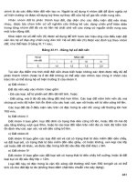
5. Residual Neutral Instantaneous Overcurrent
Protection
Residual neutral overcurrent protection is typically set well below phase overcurrent values. In
these cases, follow the previous steps but apply current in one phase at a time. It is good practice
to perform pickup tests on A-phase and timing tests on B and C-phases to make sure the relay
uses all three phases to calculate residual current.
If the phase overcurrent settings interfere with residual testing or the pickup results are not as
accurate as they should be, connect the relay and test set as shown earlier in Figure 7, but apply
all three phase currents simultaneously at the same phase angle. The magnitude of each phase
should be one-third of the test current. Some relay models need currents through all three phases
to accurately calculate residual current.
6. Tips and Tricks to Overcome Common Obstacles
The following tips or tricks may help you overcome the most common obstacles.
¾ Before you start, apply current at a lower value and review the relay’s measured values to
make sure your test set is actually producing an output and your connections are correct.
¾ If the element does not operate, watch the metering during the test if possible.
¾ Check to make sure your settings are correct.
¾ Make sure you are connected to the correct output.
¾ Check the output connections by pulsing the output and watching the relay input.
¾ Some relay test-set-inputs are polarity sensitive. If the connections look good, try reversing
the leads.
¾ Have any of your test leads fallen off?
¾ If you are paralleling more than one relay output, do all channels have the same phase angle?
¾ Check for settings like “Any Two Phases” (Any two phases must be above the pickup to
operate) or “All Three Phases” (All three phases must be higher than the pickup to operate) or
“Any Phase” (Any phase above pickup operates element).
¾ If you need more than one phase to operate the 50-element but your test set only has enough
VA for one phase, put two or more phases in series as shown below:
RELAY INPUT
TS#1
PU/2
RELAY
TS#2
PU/2
RELAY TEST SET
A & BØ Input = Pickup
+
Magnitude
A Phase Amps
+
AØ Test Amps / 2
0°
B Phase Amps
AØ Test Amps / 2
0°
+
C Phase Amps
+
+
120°
Alternate Timer Connection
DC Supply +
C Phase Amps
Element
Output
A Phase Amps
+
B Phase Amps
+
Phase Angle
+
Timer
Input
Element
Output
+
Timer
Input
Figure 19: 50-Element Alternate Relay Connection
12
Copyright©2010: Valence Electrical Training Services