SPE 21727 PA method of detecting and locating tubing and packer leak
Bạn đang xem bản rút gọn của tài liệu. Xem và tải ngay bản đầy đủ của tài liệu tại đây (818.77 KB, 5 trang )
Methods of Detecting and Locating
Tubing and Packer Leaks in the Western
Operating Area of the Prudhoe Bay Field
C.M. Michel, SPE, BP Exploration
Summary
Evaluation methods have been developed to detect cases of tubing/
annulus communication. Temperature, spinner and noise logs, as
well as fluid level detection equipment, are used under a variety of
flow conditions. Step-wise procedures are provided.
Introduction
Production in the Prudhoe Bay Unit Western Operating Area
(WOA) began in June 1977. Wells now flow naturally or with the
aid of gas lift. Rates vary from 100 to 10,000 BOPD or more and gas/
oil ratios (GOR) from 600-10,000 scf/STB. Water cuts have increased mainly in the waterflood areas and can approach 100%. The
combination of water and 12 % carbon dioxide in the dissolved solution gas forms carbonic acid, corroding tubulars despite corrosion
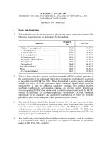
inhibition treatments. A typical completion is shown in Fig. 1. Tubing sizes range from 3- 1/2" to 7".
In the early years offield life few workovers were required. Most
of these were to replace defective packers and thermocase tubing.
An increasing number of mechanical failures of tubular components
as well as worsening corrosivity of produced fluids has significantly
increased the occurrences of tubing - annulus communication and
corresponding workover requirements. In 1988-1989, 50 cases of
tubing - annulus communication were found in the WOA. Of these,
5 were permanently repaired with wireline techniques and 3 were
temporarily repaired until a workover could be implemented. The
remaining 42 wells were shut in and worked over without attempting remedial measures.
This paper discusses methods used at Prudhoe Bay for identifying
problem wells and determining the exact location of the leak in naturally flowing, gas lifted, and injection wells.
Traditional Methods for Leak Detection
Numerous articles are available related to temperature logging for
production logging purposes.l· 2 Noise logging articles have focused on production logging or finding leaks behind casing. 3 ,4 This
work is useful to the extent that the basic concepts of tool response
still apply in tubing-annulus communication troubleshooting.
The technical literature on identifying tubing leaks consists mostly of mechanical devices run on wireline. The devices form a seal
to the tubing wall and are pumped down to the leak. Two such examples are provided in the references. 5 ,6 It is unlikely these devices
would work in North Slope wells due to the restriction at the sub surface safety valve.
Leak Detection Methods at Prudhoe Bay
Leak determination techniques for Prudhoe Bay wells have been developed which primarily employ electric line logging. The strategy
used depends on the condition of the well and whether the well is
naturally flowing, on gas lift, or is an injector. Each case is discussed
individually. The underlying strategy in almost all cases is to obtain
baseline results with the well in near static thermal equilibrium, then
alter conditions to induce temperature and time transients.
Copyright 1995 Society of Petroleum Engineers
Original SPE manuscript received for review April7, 1991. Revised manuscript received Nov,
13. 1992. Paper accepted for publication Dec. 6, 1994. Paper (SPE 21727) first presented
at the 1991 SPE Production Operations Symposium held in Oklahoma City, April 7-9.
124
Tool Selection
The optimal tool string depends in part on the magnitude of the leak.
At the lower range of leak rates (or leaks behind another string of
pipe) the noise log is often the most sensitive and the best tool for
pinpointing a leak. The temperature log works over a broad range
of leak rates, butis usually not as sensitive as the noise log. A spinner
can be used for rates above the detection limit of the tool (usually
about 6 feet/minute velocity). A philosophical approach to tool
selection is provided in Fig. 2.
Naturally Flowing Well Leak Detection
Annulus pressure readings are taken on a daily basis. Any unexplained increase in annulus pressure is cause for investigation. An
attempt is made to bleed off the pressure. The initial and final pressures along with the amount and type of fluid bled is documented.
If the pressure returns, then troubleshooting efforts begin.
Leak Detection Method. An acoustic sounding of the liquid level
in the annulus is the first step in leak detection. After non-gas lift
wells are completed they are left with a full liquid column in the annulus. Assuming no wireline work has been subsequently done to
allow wellbore gas to enter the annulus since the completion, a liquid level significantly below the wellhead is further confirmation of
a leak. Further, because the leak must be at or below the liquid level,
the level may provide an indication of the location of the leak. In one
case the entire annular fluid volume to the packer was voided.
Determination of the Leak Rate by the Non-Ideal Gas Law. The
rate of increase in the annulus pressure alone is not sufficient in determining the severity of the leak as it is a function of the leak rate
and the compressibilty of the annular fluids. For example, even a
very slow transfer of wellbore fluids into a liquid-packed annulus
results in a dramatic increase in annulus pressure. On the other hand,
the pressure of an annulus having a deep liquid level responds deceptively slow to a significant influx of wellbore fluids,
With the well shut-in, the annulus pressure is bled after noting the
initial fluid level. For low GOR wells: the fluid entering the well is
mostly liquid. The rise in annulus fluid level with time can be converted to barrels per minute (BPM). For high GOR wells: mostly gas
enters the annulus and the liquid level remains fairly constant. The
system can be modeled as a concentric cylinder of constant volume
V bounded by the wellhead at the top, the liquid level at the bottom,
the tubing on the inner radius, and the casing on the outer radius.
The influx of gas into the inner annulus from initial to final conditions can be quantified by using the non-ideal gas law:
_ 188 (P/zr- P/zi)V
Qleak (460 + T) ~t
with P expressed in psi, V in barrels, ~t in minutes, T in OF, and Qleak
in standard cubic feet per minute (SCFM).
Annular flow leak determination method. Gas flashing across the
leak provides Joule-Thompson effect cooling easily detectable on
the temperature log. This process has the advantage of being consistent with the conditions under which the leak is known to occur: that
is, hydrocarbons flowing from the tubing to annulus side. Based on
experience to date, approximately 10 SCFM is considered the minimum rate detectable by electric line logging methods. Leaks near
surface. where higher differential pressure can be established, are
more pronounced.
SPE Production & Facilities, May 1995
ALL DEPTHS ARE MEASURED DEPTHS UNLESS
INDICATED OTHERWISE
J-24
II)
II)
UJ
Z
UJ
>
SUBSURFACE SAFETY
VALVE
2087 FEET
13-3/8", 72#/FT
2701
4-_ _ 3 TO 15 GAS LIFT
i=
u
UJ
LL
LL
UJ
...J
a
a
I-
MANDRELS
4-1/2" SLIDING
SLEEVE
10420 FT
PBR
9-5/8" PACKER 10516
TOP OF 7"
LINER 10557
..
Fig. 2-Philosophical view of tool selection.
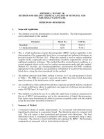
An example of the temperature log while flowing the annulus is
shown in Fig. 3.
4-1/2" "X" NIPPLE
4-1/2" "XN" NIPPLE
9-5/8" 47#/FT
10843
PERFORATIONS
11325-11355
(8890-8913 TVD)
7", 26#/FT
11700
Fig. 1-Typical Prudhoe Bay WOA well completion.
Prior to electric-line logging, tubing and annulus are both shut in
for at least eight hours. This allows the wellbore to approach static
thermal equilibrium for baseline conditions. Electric line is rigged
up and a continuous temperature log made from surface to a point
at least 200 feet below the tubing tail. Baseline data may also be acquired with the noise tool, which is included on the tool string if the
leakage rate is low and ambiguity anticipated with the temperature
logging alone.* The tool is then positioned at a point at least 200 feet
below the suspected leak while monitoring temperature.
The annulus is bled off in 400 psi stages, interspersed with temperature passes. After the initial bleed off, one expects to see increasing temperature at the stationary positioning point below the
leak. This is due to warmer (deeper) wellbore liquids gradually
flowing upwards past the tool and toward the leak. Thus, when the
"dynamic" (after bleed off) temperature passes are made they show
progressively warmer temperatures below the leak. This is usually
on the order of a 0.25 - 2°F.
The dynamic passes diverge from being warmer than the static
pass below the leak, to being colder near the leak where JouleThompson and/or latent heat of vaporization effects are occurring.
For deep leaks where low tubing - annulus ilp was induced, this
cooling effect may be only 0.5 to 3 oF. For shallow leaks with greater
ilp the effect will be far greater.
Above the leak, the dynamic temperature passes remain progressively cooler than the static pass as the cooled liquids travel up the
annulus. At some distance above the leak, typically 200-300 feet,
the dynamic passes usually approach the static pass temperatures as
thermal exchange with the surrounding formation dominates.
The intermediate temperature passes while bleeding offthe annulus in stages help pinpoint and confirm the leak.
• A discussion of noise logging techniques as it relates to leak determination is given in the
appendix.
SPE Production & Facilities, May 1995
INCREASING LEAK RATE
Annular injection leak determination method. For wells that leak
at high liquid rates (greater than 0.25 BPM), an alternative method
is to pump a liquid down the annulus and through the leak. A plug
is set first in the tubing tail. If pumping can be sustained down the
annulus with barrel for barrel returns up the tubing, then the packer
is ruled out as the communication problem. Compared to the baseline pass, the dynamic passes will exhibit the following behavior:
1) Identical temperature below the leak (static fluid).
2) A temperature spike at the leak due to friction heating (unless
no restriction exists).
3) Either cooler or warmer temperature above the leak, depending on the amount of friction heating, the pump rate, and temperature of fluid pumped (relative to original temperature of fluids
downhole).
A temperature log from troubleshooting a large leak by pumping
down the annulus is shown in Fig. 4_
For wells with packer failures, there will be no returns up the tubing. Progressively cooler temperatures will be measured from surface to the plug depth.
The troubleshooting can be done without initially setting a plug
in the tailpipe, but can be more difficult. If sufficient annular injection rate is obtained such that a high pressure drop is developed
across the leak, then friction heating is detected. Alternatively, if the
leak rate is sufficient such that the velocity in the pipe exceeds
approximately 6 feet/minute, a spinner tool can aid in detection.
The annular flow method is preferred to the annular injection
method, since it duplicates conditions under which the well is
known to leak. No plug is necessary, and plugs are best avoided due
to evaluation complications if they leak and due to potential removal
problems if they become stuck. ARCO Alaska, Inc. (the operator of
the Eastern Operating Area at Prudhoe Bay), however, has reported
successes using the annular injection method at rates down to 0.25
gallons per minute'?
Leak Detection in Gas Lifted Wells
Gas lift wells are the easiest cases to troubleshoot. The investigation
is normally completed with the well flowing at steady-state conditions on gas lift.
As a tubing leak develops, lift gas will pass through the leak. A
decrease in casing pressure is usually experienced. This is due to 1)
an increase in the total annulus-to-tubing flow area and 2) the shallower "lifting point" if the leak develops above the normal lifting
point. For the latter locations, a decrease in gross fluid production
associated with inefficient gas lift operation is also common. Table
1 provides an example.
An acoustic fluid level measurement in the annulus with the well
on lift is an important first step in troubleshooting. Various scenarios
with the corresponding acoustic sounding results are as follows:
1) Large hole, shallow leak: The liquid level can be just below the
leak, since little or no differential pressure can be developed across
the leak to unload annular fluids (which can accumulate after a shutin period). The actual distance below the leak of the annulus fluid
level will be equal to the pressure drop across the leak divided by the
125
TEMPERATURF. DEG F
9200
TEMPERATURF. DEG F
,,
,,
,
210 215 220 225
140 145 150 15S
8300
BASELINE
PASS
9300 -
8400 -
t
9400 -
9500 -
DEJYfH
IN Ff
GEOTHERMAL
GRADIENT
8500 -
,,
,,
\
t
t
9600 -
LEAKIt\G
GAS UFT
MANDREL
9700 -
DYNAMIC
PASS
9800 -
t
\
8600 -
LEAKING
GAS LIFT
MA:-.JDREL
DEJYfH
t
1:-': Ff
8700 -
t
GEOTHERMAL
GRADIENT
8800 -
8900 -
Fig. 3-ldentification of tubing leak using the annular flow method.
Fig. 4-ldentification of tubing leak using the annular injection
method.
difference in the casing gas gradient and the flowing tubing gradient
below the leak.
If the leak is higher than the shut-in tubing liquid level, then the
annulus may stay dry, even to the bottom operating gas lift valve.
2) Small hole, shallow leak: The annular fluid level can still be at
the normal lifting point. (There must be significant pressure drop
across the leak for this situation to occur).
3) Leak below the normal lifting point, small operating gas lift
valve port size: The annulus will have unloaded below the normal
lifting point all the way to the leak.
4) Leak below the normal lifting point, large operating gas lift
valve port size: Because virtually no pressure drop is taken across
the gas lift valve, the fluid will not unload significantly below this
point. Ifthis is suspected. a smaller port size or dummy gas lift valve
should be installed.
In most cases a suspected leak is easily verified by temperature
logging. The tool string used consists of a temperature tool and casing collar log. A lift gas rate of over 3 MMscflD, or enough to ensure
a significant pressure drop across the leak, is preferred.
uncertainty remains. Examples of tubing and packer leaks are
shown as Figs. 5 and 6, respectively.
A screening procedure similar to the above has been adopted as
part of production logging work. The well bore temperature is continually recorded while running in the hole. This information is also
useful for gas lift valve redesign and troubleshooting.
Leak determination method. A log of the entire tubing string to a
point 200 feet below the tailpipe is made. Where the leak is encountered, a general shift in the temperature gradient is noted. The gas
entry results in a flowing tubing temperature decrease above the
leak anywhere from 0.25 to 6 degrees, depending on lift gas rate,
fluid rates and composition, and hole size. Logging out through the
tailpipe is done to investigate any leaks at the packer, which then
show up as a cooling at the tubing tail. However, logging much below the annular liquid level is unnecessary since no lift gas could be
encountered. Any suspicious anomalies are repeated. The lift gas
can also be shut-in and a "baseline" pass made without gas lift if any
126
Injection Well Leak Detection
Injection well leaks usually present a particular challenge. Typically, the leak rate is low. Because of the higher bottomhole pressure
(compared to producing wells) even a small leak can. over time,
cause an annulus pressure approaching the wellhead injection pressure. The leaks can sometimes be temperature sensitive, leaking
only while the well is on injection with warm fluids.
TABLE 1-EFFECT ON CASING PRESSURE AND
PRODUCTION RATE OF A HOLE DEVELOPING
IN A TUBING STRING
Test
Date
Well M-10
Gross Fluid
Rate (BLPD)
Watercut
(%)
Lift Gas Rate
1/3/88
1/26/88
2/4/88
2/18/88
3/22/88
4/6/88
5/16/88
7200
6500
6200
5800
5800
5800
5800
62
63
63
62
63
63
63
3.7
4.1
4.1
4.1
4.1
4.1
4.1
(MMscf/D)
Casing
Pressure
(psi)
1785
1570
1320
1235
1240
1210
1070
SPE Production & Facilities. May 1995
9850 _
TEMPFRATURE. DEG F
TEMPIDTURf, DEG F
222 114 12<> 228
GAS LIFT
10100-
MANDREL
8z
(f)
0
Z
0
r
0
10150-
o
9900 -
§
c;")
t
SLIDING
SLEEVE
~
nn
0
9950 -
(f)
.....
R
r
10250-
GAS LIFT
MANDREL
DEPTH
I~
IT
DOWN DIP
AT HOLE
~
LEAKING
PACKER
lOCOO-
0
r
m
<
m
r
~
(")
o
c
~
R
C
r
~
o
r
DFPTH
!NIT
m
<
m
r
10050-
(f)
tn
I
0
.....
o
I
.....
10100-
10350-
10150-
10400-
Fig. 5-E-line and acoustic fluid level response for a gas lift well
with tubing leak.
Fig. 6-Temperature log and acoustic fluid level sounding on a
gas lift well with a packer failure.
Injection wells at Prudhoe Bay are either water, water-alternating-miscible gas (WAG), or gas. Many injection wells are converted
producers. Wells experiencing little or no communication problems
on water injection can have a much greater communication problem
on gas injection. Thus, troubleshooting of these wells is done while
on the gas injection cycle if possible.
Monitoring, problem detection, and leak quantification processes
for injection wells is analogous to those described for naturally
flowing production wells.
multiple sets made while running the tool into the hole. injectivity
was zero and no annular returns were apparent. After setting the tool
below the PBR, slow but definitive leak injectivity was apparent.
Gas Injection Well Leak Detection
For wells with significant leaks an identical strategy to that used for
naturally flowing producing wells is used: a baseline temperature
pass under near static conditions is made, followed by bleeding the
annulus in stages interspersed with dynamic temperature passes. In
one (extreme) example, a well with a leak at 1,021 feet exhibited 56
degrees of cooling compared to the baseline pass. Most other wells
have not been as easy to identify because the leaks were deeper and
slower. For troubleshooting these wells a noise tool is usually included in the tool string.
If the above method is unsuccessful, a plug is set in the tubing tail.
The annulus is allowed to reach an equilibrium pressure. The tubing
is pressurized with gas, and the annulus pressure is bled off. If the
annulus pressure returns to its original value and the tubing pressure
does not change, a packer leak is indicated. If tubing pressure drops
as annulus pressure increases, then the leak is somewhere in the tubing string. If the leak is in the tubing string, then a slug of liquid is
pumped into the tubing and allowed to fall. Once in place, its top can
be verified with an acoustic liquid level device. The tubing is pressurized with gas and then shut in. If technique is successful, the liquid level will slowly move to the location of the leak and stop. The
exact location of the liquid top can be verified by using a fluid identification device such as a density or capacitance type electric line
tool.
Water Injection Well Leak Detection
A plug can be set in the tail pipe and pumping done down the tubing
or annulus, similar to the method described for naturally flowing
producing wells.
In one 7" completion with no nipple profiles that leaked at a very
slow rate, a modified Baker-Lynes inflatable packer set with coiled
tubing was used to confirm a leak at the PBR. (The poppet valve was
removed allowing multiple sets with the same packer.) During the
SPE Production & Facilities, May 1995
Recommendations
I) Do not rely heavily on hydrostatic head calculations to determine the leak location. If anything, annulus pressure tends to be
higher than what would be calculated for a given depth of tubing/annulus communication.
2) Prior to investigating with electric-line logging, attempt to duplicate the conditions under which the logging will be done. For example, shut the well in first for 6-8 hours. Then bleed off some annulus pressure and note the rate of annular pressure/liquid level
build-up. Some leaks are thermally related and cease after the well
is shut in (necessary for a baseline pass).
3) There are numerous individual ways to pinpoint the leak location, many of which involve combinations of the aforementioned
techniques. It is important to determine ahead of time what type of
log response is anticipated. This can impact the tools to be selected
and the sequence of actions planned.
4) In most cases it is best to use the reservoir as the pressure
source (annular flow method) rather than pumping liquid down the
annulus (annular injection method).
5) When possible, get baseline measurements prior to inducing
tubing/annulus communication. This will provide a greater degree
of confidence in the results.
Nomenclature
Pi =
Pf=
Zi =
Zf=
T=
V=
L'l.t =
Qleak =
initial annulus pressure, psi
final annulus pressure, psi
Z factor, initial conditions
Z factor, final conditions
annulus temperature, OF
volume of annulus from wellhead to liquid level, bbls
elapsed time in minutes
leak rate in standard cubic feet per minute (SCFM).
Acknowledgments
The contribution of the members of the BP Exploration (Alaska)
North Slope Production Engineering department are gratefully acknowledged. Julie Heusser and David Smith of ARCO Alaska, Inc.
provided me with further insights and examples.
127
Mlll.I\I ()L· I~
(WG S(JIJ.t:)
HICH
't~
NOISJ::
~IUQUI::J"l:Y IY\"'DWIUlH ~
(SCHI.UMII~R(;t:I(1
Fig. 7-Noise log for a well with a packer failure.
The techniques and/or conclusions are those of the authoring
company and may not be shared by the other Prudhoe Bay Unit
Working Interest Owners.
References
I. Smith, R. C., and Steffensen. R. J., "Improved Interpretation Guidelines
for Temperature Profiles in Water Injection Wells," SPE Paper 4649. Society of Petroleum Engineers. Richardson. Texas, 1973.
2. Curtis, M. R.. and Witterholt, E. J., "Useofthe Temperature Log for Determining Flow Rates in Producing Wells," SPE Paper 4637, Society of Petroleum Engineers, Richardson, Texas,1973.
3. McKinley, R. M. and Bower, F. M. "Noise Logging: Theory, Art of Interpretation, and Operational Procedures," July 1976.
4. McKinley, R. M., Bower, FM, Rumble, R.C.: "The Structure and Interpretation of Noise From Flow Behind Cemented Casing," 1. Pet. Tech. P.
329-338 March 1973.
5. Norris, JD. Tubing Leak De tector for Wells, and Method of Operating
Same. US Patent No. 3,342.06 1.
6. Hubbard. Glen O. Locating Holes in Tubing. US Patent No. 3,696,660.
7. Huesser. Juli e and Smith, David, ARCO Alaska, Inc. Personal conversation.
8. Schlumberger software manual.
R. M. McKinley (Exxon Production and Research Company) has
published much of the research on noise logging, much of which has
been oriented toward its uses as a production logging tool and identifying channels behind casing. He reports that single phase fluids
produce higher noise levels in the 1000-2000 Hz range (4). Gas expanding into a water-filled channel produces increased noise in the
200-600 Hz range.
Typical noise logging equipment filters the signal into various
frequency windows (Fig. 7 from Schlumberger (8». Field results to
date have found increases in noise levels in all windows in the vicinity of the leak. An example from a packer leak is provided (Fig. 7).
Noise logging is a slow process. Discrete stops must be made,
each requiring nearly one minute. Noise attenuation in liquid is low,
so stops can be widely spaced (10 - 500 feet). Attenuation in gas
filled tubing, however, is high and stops should be made only two
feet apart.
The noise tool is typically run on the same string as the temperature tool. When in the noise data acquisition mode, no temperature
or casing collar log data is available. All possible extraneous surface
noise should be eliminated when noise logging.
51 Metric Conversion Factors
bbl x 1589 873
ftx3.048 *
ft 3 x 2.831 685
psi x6.894757
OF (OF-32)/\.8
·Conversion factor is exact.
E-OI = m3
E-OI=m
E -02= m3
E+OO=kPa
= °C
SPEPF
C. M. Michel is a Senior Production Engineer for BP Exploration
(Alaska). He is currently involved in hydraulic fracturing. He received a BS degree in chemical engineeri ng 1978 and MBA in
1982. both from Oregon State U., and worked as a process engineer in the pulp and paper industry between degrees. He
joined Sohio Petroleum (later BP Exploration) in 1982 and has assumed various production engineering assignments. Michel is a
registered petroleum engineer in Alaska.
Appendix-Noise Logging
Noise logging can provide additional information on the location of
the leak.
128
SPE Production & Facilities, May 1995