Developing service VOIP in Viet Nam
Bạn đang xem bản rút gọn của tài liệu. Xem và tải ngay bản đầy đủ của tài liệu tại đây (741.16 KB, 71 trang )
Telecom project: Developping Service VOIP
Ha Noi open university
Center For International training Cooperation
Thesis:
Teacher : Nguyễn Thái Nguyên
Group 3 : Đồng Xuân Thắng -Cap
Lê Trọng Nghĩa
Nguyễn Xuân T
Mai Trọng Dũng
Bùi Thanh Nhàn
Ngô Thị Nhàn
Hà Nội ngày 15/1/2006
Groups 3 - Đồng Xuân Thắng - cap.
1
Telecom project: Developping Service VOIP
Glossary
ATM :
ACELP :
ARQ :
ACF :
DES :
PSTN :
PC :
PCM :
IP :
ITU :
IETF :
ISUP :
INAP :
ITSP :
MAP :
MGCP :
MTP :
MP :
MCU :
OLC :
QoS :
RC :
RSVP :
RTCM :
RTP:
SIP :
SS7 :
SCCP :
STP :
TCP :
TCAP:
UDP :
VAD :
VoIP :
Asynchronous Trasfer mode
Algebraic Code Excited Linear Predictive
Automatic Rrepeat Request
Admission Confirm
Data Encryption Stadard
Public Switched Telephone Network
Personal Computer
Pulse Code Modulation
Internet Protocol
International telecommunication Union
Internet Engineering Task Force
ISDN User Part
Intelligent Network Application Part
Internet Telephony Service Provider
Mobile Application Part
Multimedia Gateway Control Protocol
Message Trasfer Part
Multi point
Media Control Unit
Open Logical Channel
Quality of Service
Report Court
Resource Reservation Protocol
Real Time Control Mode
Real Time Post
Session Initiation Protocol
Signal No.7
Signaling Connection Control Part
Signaling Transfer Point
Transmission Control Protocol
Transaction Capabilities Application Part
User Data Package
Voice Activity Detector
Voice over Internet Protocol
General of the thesis
VoIP -Voice over Internet protocol
Groups 3 - §ång Xuân Thắng - cap.
2
Telecom project: Developping Service VOIP
VoIP ( Voice over IP- that is, vioce delivered using the Internet Protocol) is a term
used in IP telephony for a set of faccilities for managimg the delivery of voice
information using the Internet Protocol(IP). In general, this means sending voice
information in digital form in discrete packets rather than in the traditional circuit
– committed protocols of the public switched telephone network (PSTN). A major
advantage of VoIP and Internet telephony is that it avoids the tolls charged by
ordinary telephone service.
VoIP, now used somewhat generally, derives from the VoIP Forum, an effort by
major equipment providers, including Cisco, Vocltec, 3 Com, and Netspeak to
promotethe use of ITU-T H.323, the standard for sending voice (audio) and video
using IP on the public Internet and within anintranet. The Forum also promotes the
user of directory service standard so that user can locate other users and the use of
touch-tone signals for automatic call distribution and voice mail.
In addition to IP, VoIP uses the real-time protocol (RTP) to help ensure that
packets get delivered in a timely way. Using public networks,it is currently
difficult to guarantee Quality of Service (QoS). Better service is possible with
private network managed by an enterprise or by an Internet telephony service
provider (ITSP).
A technique used by at least one equipment manufacturer, Netspeak, to help
ensure faster packet delivery is to Packet Internet or Inter- Network Groper (Ping)
all possible network gateway computeres that have access to the public network
and choose the fastest path before establishing a Transmission Control Protocol
(TCP) sockets connection with the other end.
Using VoIP, an enterprise positions a “VoIP device” (such as Cisco ’s AS5300
access server with the VoIP feature) at a gateway. The gateway receiver packetixed
voice tranmissions from users within the company and then routes them to othe
parts of its intranet (local area or wide area netnork) or using a T- carrier system or
E-carrier interface, sends them over the public switched telephone network (PSTN)
Groups 3 - Đồng Xuân Thắng - cap.
3
Telecom project: Developping Service VOIP
Chapter1:Voice over IP (VoIP) Technology
1. Fundamental features of channel switching network and Internet:
1.1. Fundamental features of channel switching network:
The
channel switching network is designed for rapid connect and
eliminating the ineffectiveness of time-consume on connecting. In the channel
shifting network, the user is provided a conductive channel to exchange
information together. When the exchange completed, the conductive channel is
released. This could lead to loss because of limits of conductive channel. The
utility is low but ensures the calling quality because a two-way 64 kbps channel
is set aside for caller and receiver. The channel shifting network is designed
optimum for real transmission time with high service quality. In the channel
switching network, all terminal equipment and switch board are inserted a fixed
number so no need to enter address for information exchanging process. The
switching system in channel switching network will base on the address of
called subscriber to define the conductive line. Because the band width is
ensured not be changed during calling, calling fee of channel switching network
is based on distance and calling time.
1.2. Fundamental features of Internet:
Internet is the package switching network suitable with applications that
are not exchanged according to the real time; Package delay doesn’t effect
strongly on service quality like email and file transmission. Package switching
networks don’t set aside a fixed line between two users, so, not ensure the
service quality. All information on the network are divided into packages, these
packages contain the destination address and its order.
Channel fixer and host on the network will send these packages to the
targeted address. On Internet, all packages are treated the same with out
distinguishing their contents. When packages to the destination address, they
will be arranged according to the initial number. By form of package
information transmission, the utility is maximum. However, real time
applications will be greatly effected on service quality. The fee is not calculated
on distance or time but on used band width. On Internet, on address of package
Groups 3 - Đồng Xuân Thắng - cap.
4
Telecom project: Developping Service VOIP
is marked by IP address, the IP address will be named for the host and terminal
stations. Channel fixing will be controlled by the IP destination address. To
create a understandable, convenient address type for the IP address by name like
service of regional name or email address.
Because the limit of IP address, the users are temporarily inserted IP while
dialing. The IP address is only for one terminal equipment while connecting
Internet and deleted while not connecting. The deleted IP address will be used
for another connecting on the network.
1.3. Advantages of VOIP against PSTN:
The users will pay for used time of PSTN if more time for call establishment,
more increased fee to be paid. At one time, they can contact to one person. But
with VoIP, the time for call establishment is independent to subscriber’s fee. One
subscriber could have calls to different ones and exchange data, dialogue, pictures,
paintings and video with other subscribers.
Figure 1: The basic structure of telephone network by IP
Groups 3 - Đồng Xuân Thắng - cap.
5
Telecom project: Developping Service VOIP
1.4. Outlook of VoIP technology:
+ Some technical features of IP telephone:
By analysis of fundamental features of channel switching network and
Internet, we see that it is typical to accumulate real time signal into the package
switching network and IP telephone. Firstly, we should classify IP telephones.
All IP telephones change according to 3 characters: type of terminal equipment,
position of gateway, between IP and PSTN networks and main transmission
equipment.
a. Terminal equipment and gateway: There are 03 main types of IP. They are PC
to PC, PC to Phone, Phone to Phone.
+ PC to PC is the first model of IP telephone. Users at two ends of PC to PC
should have 1 PC that is equipped audio, a software and connected to
Internet. This service no need gateway and PCTN because PCTN never switch
these calls, the main transmission tool is public Internet. Due to sound quality
and complexity of use, the PC to PC has a litter affect on traditional telephone
service.
+ PC to Phone expands the number of users but for exploiters, the call of PC to
Phone is more complex than that of PC to PC.
+ Phone to Phone is very important market including mainly commercial
services, because, people prefer to communicate by phones. However, the 3 rd
model of IP requires more investment capital because it needs input gateway
to PSTN near places providing service. Services of Phone to Phone are nearly
similar to that of traditional telephones.
b. Transmission equipment: The classification between IP and VoIP telephone is
based on the nature of main transmission equipment. IP telephone is for voice
transmission, fax and services relating to package switching networks on IP.
Internet phone and VoIP are basic types of IP. Internet phone is IP in which
the main transmission network is public Internet (global super-network).
Voice over IP is IP in which the main transmission network is private-used
one basing on IP.
Groups 3 - Đồng Xuân Thắng - cap.
6
Telecom project: Developping Service VOIP
Besides, being the replacing tools for distance and international phone, the IP
technology creates a plenty of other services that can transmit every service by
IP. This part only mentions the technology of VoIP and interests in the terminal
equipment that is telephone on the channel switching network (Phone to Phone).
Figure 2: IP call: Phone to Phone
+ Special features of VoIP:
a. Adjustable quality: The quality of VoIP depends on each part (coding and
low speed re-coding for each part). Internet is not specific service network,
the exchanging methods are entirely selected by terminal systems. Thus, the
terminal systems can control the compressed volume on the network
bandwidth or content for transmission.
b. Security: Using SIP to order a password and confirm messages indicating the
terminal. RIP make and the password to be the password of transmission
method. Therefore, all program is coded to secure transmission.
c. Users interface: Terminal systems of VoIP have plentiful indications and can
give out instructions and various graphic interface.
d. Connecting telephone and computer: Available to solve these complex
connections.
1.5. Conclusion:
Groups 3 - Đồng Xuân Th¾ng - cap.
7
Telecom project: Developping Service VOIP
The VoIP technology has potential for future development, ability to replace
the existing PSTN network. Due to differences in features of channel switching
network and Internet, to apply VoIP for users of channel switching network
(Phone to Phone), these differences should be solved. Concretely, there should
be address changes, indication of two networks and proper inter-code for
application of time transfer on network.
2. Problems relating to VoIP technology and talk quality on VoIP:
Using the traditional channel switching telephone network will cost much
when at distance, to reduce expenses for distant calls, use public data network
or private data network for communication. The package switching network that
applies IP is example. Using the package switching network by IP to transmit
the talking signals. Voice over IP-VoIP is good basis to design global multiinstrument transmission system that can replace the infrastructure of existing
network. Accumulating Audio, Video, data, fax... into a single common
network on IP technology. It is possible to apply the Frame relay or
unsynchronous transmission technology ATM to replace IP technology. The
VoIP is more economic for distant call, because the fee is calculated by the
width of bandwidth, not by distance. In IP, it uses talk compressing technology
to save band width leading to cost reduction but the IP’s quality not as good as
that of PSTN.
The biggest difference when applying into the multi-instrument network is
actual time service non-actual one. With actual time service and like Audio,
Video... not allow over-delay on the network; in non-time network like email,
file transmission, the delay is not worthy worrying. So, to carry out VoIP,
special compressing and coding methods should be used to reduce the speed of
talk signals that can’t be use 64 tps like channel switching.
2.1. Coding techniques and talk signal compression:
In
talk transmission, voice is usually numberidized and coded PCM by
Rule A or U with speed of 64 Kps recorving sound rather actual. For some
specific applications such as transmitting talk signals on TP network, sounds are
transmitted with lower speed, so, there should have coding techniques and talk
Groups 3 - Đồng Xuân Thắng - cap.
8
Telecom project: Developping Service VOIP
signal compression to lower speed according to standard of ITU and ETSI like
G723.1; G729; G729A; GSM.
+ Standard G7213. According to the standard of ITU, the coding has 5.3Kbps
and 6.3Kbps. The compression technicque uses MP-MLQ for high bit speed;
for coding with low bit speed using ACELP. Delaying against algorithm is
67.5ms.
+ Standard G.729. According to the ITU standard, this coding has speed of 8
Kbps. This compression techniques uses algorithm predicting coded linear
linked structure algebra excitation. Delaying against algorithm is 25ms.
+ Standard GSM06.10. According to ETSI, this code has 13Kbps. This
compression technique is regular pulse excitation and long-term predictor.
Delaying against algorithm is 40ms.
2.2. Voice Activity Detector (VAD):
VAD is carried out by numeric signal processor to reduce the talk intensity
that is transmitted by automatically detecting the dead space on the talk and
stopping transmitting at that time. There are space approx. 50-60% of almost
talks. This always occurs because when one speaking, the other must listen to.
VAD allows band width for dead space saved for reserving other data.
VAD actives by controlling power of talk signals; power change is change of
talk signal frequency. The difficult of VAD is to define the exact time of talk
ending and of talk signal. The double VAD is nearly 200ms after recognizing
talk signals and stop and detect package processing. This top prevent VAD from
missing the end talk or in the middle of small interrupt in talks.
2.3. Number and address:
Due to cooperation between IP and SCN networks, there will be 2 types of
address: address in CSN and in IP.
a. Numbering on SCN network:
On the channel switching network, all terminal and switchboard are fixed a
number. Number E164 is telephone numbers subject to the structure and
numbering program that were described on the proposal E164 by International
Groups 3 - Đồng Xuân Thắng - cap.
9
Telecom project: Developping Service VOIP
Telecommunication Union. The line fixing process on the channel switching
network is controlled by the address system of E164. Before dialing, the users
of channel switching network have to dial E164 and callee’s number.
+ Local number:
Code of Access Caller + National Post + National Destination Code +
+ Subscriber number.
+ For international numbers, we can use 03 following structures:
Code of Access Caller + International Post + Country Code + Identification
Code + Subscriber number.
Code of Access Caller + International Post + Country Code + Destination
Code + Subscriber.
Code of Access Caller + International Post + Country Code + Global
Subscriber’s Number.
b. Numbering on IP:
+ Prefix is an identifier including one or more numbers allowing the used
numerical types, network and service and can be used to select service
provider, type of service in a nation.
+ Selecting service provider including numbers that allow to select service by
IP network or SCN and there of to select appropriate switching.
+ Selecting service provider can be done by ways: pre-select by user or dialing,
password.
Incase, the Gateway connects to SCN where there are a lot of service providers,
both Gateway and Gatekeeper should be able to identify and process the
selected code of service provider. Incase, a lot of service providers on IP
network, Gatekeeper is able to identify and process the selected code of service
provider.
To get the most common address types on Internet, it can use name address like
email address: user@domain, user@host , user@IP-address , phonenumber@gateway.
Groups 3 - Đồng Xuân Thắng - cap.
10
Telecom project: Developping Service VOIP
2.4. Fee:
To ensure the effectiveness of network, the fee calculating will be done by
a separate host system. The fee-calculator host will be responsible for collecting
and reserving all detail of call from gateway or MGC. These data are used to
make invoices for customers. Customers ca access into the host for their fee
details on the website. The fee will be calculated by the used time. The fee
calculating system should be able to calculate on 2 types of service: pre-paid
and post-paid. This software must be able to carry out some following function.
- Accepting call.
- Informing the amount of account.
- Fee calculating based on pre-fixed level for different directions.
- Informing the maximum time of call.
- Updating account’s amount after calling.
2.5. Signal cooperation:
The standard of signal communication of IP Phone to PSTN is suggested to
be signal No. 7 (SS7). The SS7 is used to transmit following information:
- Information o call establishment.
- Information about call control.
- Property and application.
The signal communication between 2 IP networks and signal network 7 of PSTN
is carried out by signal Gateway. The signal gateway connects to STP on the SS7
as a SP and transfer signals fully. The signal Gateway should support signal
news ISUP and SCCP/TCAP.
Using the signal communication No. 7, IP telephone network will bring benefits
as follows:
- Fully connecting to PSTN.
- Supplying additional services.
- Improving call control.
- Improving maintaining property for trunk.
- Speeding up call establishment.
Groups 3 - Đồng Xuân Thắng - cap.
11
Telecom project: Developping Service VOIP
Although new signaling, ssuch as H.323 ans SIP, exist for VoIP net
works the standard in traditional telephony and in mobile networks is SS7.
Therfore, if a VoIP based network is to communicate with any traditions
network, not only must it network at the media level through media gateways,
it must also interwork with SS7. To support this, the IETF has developed a set
of protocols known as Sigtran.
In order to understand Sigtran, it is worth considering the type of inter
working that needed to occur. Imagine, for example, an MGC that control one
or more media gatways. The MGC is a call control entity in the network and,
such as uses call control signaling to and from other call control entities. If
other call control entities use SS7 then the MGC must use SS7 at least to the
extent that the other call control entities can communicate freely with it. This
means that the MGC does not necessarily need to support the whole SS7- just
the necessary application protocols.
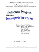
Consider figure 3 which shows the SS7 stack. The bottom three layer are
called the Message Transfer Part (MTP). This is set of protocols responsible
for getting a particular SS7 message from the source signaling point to the
destination signaling point. Above the MTP we find either the Signaling
Connection Control Part (SCCP) or the ISDN User Part (ISUP). ISUP is
generally used for the establishment of regular phone calls. SCCP can also be
used in the establishment of regular phone calls but it is more often used for
the transport of higher layer applications, such as the GMS Mobile
Application Part (MAP) or the Intelligent Network Application Part (INAP).
In fact most such application use the services of the Transaction Capabilities
Application Part (TCAP) which in turn uses the services of SCCP.
Application Part
ISDN User Part
(ISUP)
Transaction Capabilities
Application Part (TCAP)
Signaling Connection Control
Part (SCCP)
MTP Level 3
MTP Level 2
MTP Level 1
Figure 3: SS7 Stack
Groups 3 - Đồng Xuân Thắng - cap.
12
Telecom project: Developping Service VOIP
SCCP provides an enhanced addressing mechanism to enable signaling
between entities even when those entities do not know each other’s signaling
addresses (known as point codes). This addressing is known as global title
addressing. Basically it is a means wherby some other address, such as a
telephone number, can be mapped to a point code, either at the node that
initiated the message or some other node between the originator and
destination of the message
Figure 3 provides some examples of communication between different
SS7 entities. Consider scenario A. In this case, the two entities, represented
by point code 1 and point code, communicate at layer 1. At each layer, a peer
to peer relationship exists between the two entities. Scenario B has a peer to
peer relationship at layer1, layer 2, and layeer 3 between point codes 1 and 2,
2 and 3, and 3 and 4. At the SCCP layer, a peer to peer relationship exists
between point codes 1 and 2 and between point codes 2 and 4.
At the TCAP and Application layers, a peer to peer relationship can
only take place between point codes 1and 4. In other works, the application at
point code 1 is only aware of the TCAP layer at point code 1 and application
layeer at point code 4.Similarly the TCAP layer at point code 1 is aware only
of the application layer above it, the SCCP layer below it, and the
corresponding TCAP layer at point code 4. It is not aware of any of the MTP
layer. Equally, if we consider communication between point code 2 and point
code 4, the SCCP layer at each point code knows only about the layeer above
(TCAP), the layer below (MTP3), and the corresponding SCCP peer. As far as
the SCCP layers are concerned, nothing else exists. Therefore, SCCP neither
knows nor eares that point code 3 exists. Consider Scenario C, where ppoint
code 3 is replaced by a gateway that supports standard SS7 on one side and an
IP based MTP emulation on the other side. Point code 4 does not supportr the
lower SS7 layeers at all- just an MTP emulation over IP. Provided that the
MTP emulation at point code 4 appears to the SCCP layer as standard MTP,
then the SCCP layer does not care, not do any of the layers above SCCP.
Equally the SCCP layers at point code 1 and 2 do not care. Consequently, it is
possible to implement SS7 based applications at point code 4 without
implementing the whole SS7 stack. This is the concept behind the Sigtran
protocol suite.
Groups 3 - §ång Xuân Thắng - cap.
13
Telecom project: Developping Service VOIP
ISUP
ISUP
MIP3
MIP3
MIP2
MIP2
MIP1
MIP1
Point code 1
Point code 4
Scenario A - Communication Between Adjacent Signaling Points
Application
Application
ICAP
ICAP
Sccp
sccp
sccp
MTP3
mtp3
MTP3
MTP3
MTP2
mtp2
MTP2
MTP2
MTP1
mtp1
MTP1
MTP1
Point code 1
Point code 2
Point code 2
Point code 4
Scenario B - Communication Between non- Adjacent Signaling Points
Application
Application
ICAP
ICAP
sccp
sccp
sccp
MTP3
mtp3
MTP3
MTP
MTP
MTP2
mtp2
MTP2
emulation
emulation
MTP1
mtp1
MTP1
over IP
over IP
Point code 1
Point code 2
Point code 2
Point code 4
Figure 4 Example SS7 Communication Scenarios
Groups 3 - §ång Xuân Thắng - cap.
14
Telecom project: Developping Service VOIP
2.6. Confidence:
The
IP service active on the base of IP switch, the requirement of
confidence is very important for:
+ Protecting exploiters from bad activities.
+ Protecting exploiters from network troubles by faults of network components.
+ Protecting users from bad activities.
To ensure above targets, the network should protect for 5 following services:
- Confirmation.
- Acceptance.
- Refuse.
- Privateness.
- Security.
An IP system can have one oral above services depending on each specific
case and even each specific subscribe. For network exploiers, protecting
important information from illegal access is put on top. Below are some
suggestions:
+ Data Coding: This is the most effective practical method to protect
information that are transmitted through different networks. Regularly, the
data is compressed by different standards by Gateway, may be, no need to
code the data. If necessary, information on network are advised to code by
DES (Data Encryption Standard) with the key of minimum 56 bit long.
+ Anti-virus: Virus can cause significant consequences to the software of all
system. Virus could be spread from other system or customers’. This also
carries significant meaning when the system operates on base of the
dispersion processing structure. Anti-virus software should be installed on
Gateways and hosts of gatekeeper.
+ Using Firewall: This is important method to protect the network of exploiter.
There are 2 basic mechanism of Firewall are to stop information and allow
Firewall information to- Stop all coming data except the resource is confirmed.
Groups 3 - Đồng Xuân Thắng - cap.
15
Telecom project: Developping Service VOIP
- Release all data except for propaganda and regional checking data.
Even, using firewall is effective, to ensure high confidence, coding and
confirming methods should be used.
+ Confidence for distant access:
To control distant access, there are following methods:
- Confirmation: Distant subscribers should be controlled.
- Access Limit: Fixing each distant subscriber a specific position on server.
- Time limit: Fixing connecting time, if it is over, connecting will be
cancelled.
- Connecting limit: Limiting on connecting times and starting points of
connect.
+ Confidence policy:
Confidence plan should include following elements:
- Definition of access levels regulating user to access into relevant resource.
- How a subscriber on subscriber group access into the network.
- Access Regulations: Time, place and how to use services.
- Instructions for fee calculation.
- Requirement on network accessing and connecting.
- Ability to strengthen confidence methods in specific cases.
- Instruction on confidence for users.
2.7. Troubles relating to calls quality:
+ Delay:
- Algorithms delay: This is caused by Codec and naturally - created by
coding algorithm.
- Package delay: This is necessary time to delivery a IP package. And also
suffer from delay when passing saving equipment and transition
equipment, for example, passing line fixer or switcher.
Groups 3 - Đồng Xuân Th¾ng - cap.
16
Telecom project: Developping Service VOIP
- Wave transmission delay: This is necessary time for optical or electric
signals on transmission environment to certain geographic distance.
- Structuring delay: This is delayed time created by different components in
a transmission system. For example, a frame across a line fixer should
move from Gate to Door across server body. There is a minimum delay
through server body and changeable delay by in line and processing of line
fixer.
+ Echo suppression.
The first trouble caused by the delay is echo impact. The echo can be
occurred on a talk network by chain-jointing between the listening and speaking
parts of the complex. This delay is called auscosic delay. This also occur when a
part of power energy is reflected to the speaker by a exotic line in PSTN, that
called echo.
If the time of one-way delay or terminal delay is short, every echo created
by talk line is back to the speaker rapidly and non-noticeable. In reality, no need
echo suppression if one-way delay is smaller 25ms. However, the one-way
delay of VoIP almost over 25ms, so the echo suppression is required.
+ Superposition of voice
If the best ability of echo suppression, switching 2-way talk become very
difficulty when the delay is too long causing voice superposition. This occurs when
one party reduces voice of the other when the delay is too large.
+ Jitter - Changeable delay.
While phone services require to transmit according to the fixed delay, the
data network that badly transmit and can’t supply the fixed delay because
different packages have different delay, so, different delay frame. Resources
create regularly frames, the Destination gate can’t collect these frames regularly
because of Jitter. Jitter interrupts the call and difficult the talk content. To
remove the changeable delay, it should receive frames and keep them for
enough time. So that the latest frames come timely for reading in order. The
buffer can remove the fitter. No worry on this for PSTN, because, the bandwidth
is fixed. Volume of Jitter is more big, the longer frame kept on the buffer and
Groups 3 - Đồng Xuân Thắng - cap.
17
Telecom project: Developping Service VOIP
create more time delay. If the Jitter is small, use small buffer. If Jitter increased
by increase of loading, the size of buffer will automatically increase.
Packages will destine after some fixed time (for example, after 20ms).
Incase of Jitter, this is not true. The figure below illustrates the Package 1 (P1)
and package 3 (P3) coming timely; but Package 2 (P2) and Package 4 (P4) late
for 12ms and 5ms against expected relatively.
Figure 5: Jutter description
+ Package loss:
The IP network doesn’t ensure to fully and orderly distribute packages.
Package will be lost if blocking (be broken by transmission line or insufficiency
in capacity). Due to, the sensitive of talk transmission, the transmission rules
are based on TCP, it will be no effective. If talk sample is lost on the terminal
talk, ignore the gap at this line. If too much package are lost, the voice will be
broken. To cover, replaying previous packages. This is only done if some
samples are lost. In case of group faults, take interpolation by using previous
packages and re-coding set will product what lost package is. In reality, to apply
IP network for high service like video, mobile and high-quality talks, another
signal system is required to solve this, it is signal system No. 7.
+ Bandwidth:
A traditional talk uses a 64Kbps flow. When the talk flow is on IP network,
it will be compressed and numericalizied by Digital signal processor. This
compression reduce speed of talk to 5.3Kps for a talk, then, packed into IP
Groups 3 - Đồng Xuân Thắng - cap.
18
Telecom project: Developping Service VOIP
network, IP/UDP/RTP starters are added. This large the band width for each call
(about 40 byte for each package). However, technology for example, for
compressing the RTP starter may reduce the IP starter to 2 bytes. The bandwidth
depends on byte coding speed and talk package size. The private IP network has
more advantages than Internet does because of more bandwidth so, voice quality
is better. Defining the bandwidth on the network, number of call at peak time.
VoIP can reduce the bandwidth by talk signal compression and dead
suppression.
3. Transfer modes:
TCP and UDP are two modes for data transmission on IP network.
+ TCP is good protocol for data transmission that can control flow and block,
protect from over-loading on the network. However, there are some
unfavorable matters when using the TCP mode. Due to the reliability of leyte
service and retransmission of lost packages increasing the delay of network.
TCP has a lot of properties and complexity, this is not benefit for VOIP
technology. When transmitting talk signals, they should be distributed to
users at the same time. On TP network, there should have effectiveness for
distributing multi transmit-feedback data, however, TCP can’t supply this. If
the data are distributed to destinations on TCP, single TCP will be required to
connect causing cost of bandwidth.
+ UDB is protocol simpler than TCP, just an expanded ID mode, only used
when no requirement for high quality service. This protocol has advantage
that no waste of time for re-transmission of lost packages.
It can use the property of multi-transmit and feedback and save bandwidth
when data sent to a lot of destination. UD Palso has disadvantages, no
synchronous mechanism and no means to control flow and block. To solve this
matter, cooperate UDP and modes controlling the real time.
3.1. Real time mode:
3.1.1. Real Time Post:
RTP can distribute among terminals of real time services like audio, vide.
The typical RTP is used to transmit data through UDP (User’s Data Package).
RTP and UDP supply functions of protocol transfer. UDP supplies multiGroups 3 - Đồng Xuân Thắng - cap.
19
Telecom project: Developping Service VOIP
elements and error checking service. RTD is also used with other transfer
protocol. When a host desires to send a package, it should know transmission
measure to make package shape, add the specific transmission measure into the
title of package to pre-decide the RTP’s title and put into the lower layer
transmission measure. Then, send to network by multi transmit-feedback or
single transmit-feedback ways to other participants.
Format of RTR fields are described as follows:
P header
20 bytes
DP
8 bytes
TP header
12 bytes
CODEC sample
Figure 6: News on real time Post Mode
Fields of RTP header are:
+ Version (V, 2 bytes) defines version of RTP.
+ Padding (P, 1 byte). If padding is installed, a package contains one or more
Octet padding adding to the terminal that not belong to pay load. The final
Octet of padding includes number of ignored octet padding. Padding may
need more other coding algorithms with changeable sizes of block or bring
some RTP packages in low layer data unit mode.
Groups 3 - Đồng Xuân Thắng - cap.
20