GIỚI THIỆU CHUNG VỀ HỆ THỐNG ĐIỆN
Bạn đang xem bản rút gọn của tài liệu. Xem và tải ngay bản đầy đủ của tài liệu tại đây (4.34 MB, 57 trang )
8/19/2014
CHỨC NĂNG
CÁC HỆ THỐNG TRUYỀN TẢI
VÀ PHÂN PHỐI ĐIỆN NĂNG
Chương 1
GIỚI THIỆU CHUNG VỀ
HỆ THỐNG ĐIỆN
Võ Ngọc Điều
Bộ môn Hệ Thống Điện
Email:
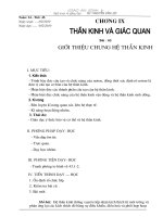
Power System Structure
- A typical power generation, transmission and distribution system has these
components:
Power Generation Plants
Substations
Step-up Transmission Substation
Step-down Transmission Substation
Distribution Substation
Underground Distribution Substation
Substation Functions
Substation Equipment
Transmission Lines
Overhead Transmission Lines
Subtransmission Lines
Underground Transmission Lines
Distribution Systems
Industrial Customer
Commercial Customer
Residential Customer
Transportation Customer
2
1
8/19/2014
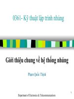
Power Generation Plants
- A power generation plant is a facility designed to produce electric energy
from another form of energy, such as:
• Heat (thermal) energy generated from:
fossil fuels;
coal
petroleum
natural gas
solar thermal energy
geothermal energy
nuclear energy
• Potential energy from falling water in a
hydroelectric facility
• Wind energy
• Solar electric from solar (photovoltaic) cells
• Chemical energy from:
Power Generation Plant to
transmission line
fuel cells
batteries
3
Power Generation Plants
- There are many different types of electric power generating plants. The
major types generating electric power today are shown below.
Fossil fuel power plant
Hydroelectric power plant
4
2
8/19/2014
Power Generation Plants
Solar thermal power plant
Nuclear power plant
5
Power Generation Plants
Geothermal power plant
Wind power towers
6
3
8/19/2014
Substations
- A substation is a high-voltage electric system facility. It is used to switch
generators, equipment, and circuits or lines in and out of a system. It also is
used to change AC voltages from one level to another, and/or change
alternating current to direct current or direct current to alternating current.
Some substations are small with little more than a transformer and associated
switches. Others are very large with several transformers and dozens of
switches and other equipment. There are three aspects to substations:
Typical substation
7
Substations
- Substation Types: Although, there are generally four types of substations
there are substations that are a combination of two or more types.
Step-up Transmission Substation
Step-down Transmission Substation
Distribution Substation
Underground Distribution Substation
Substation Functions
Substation Equipment
8
4
8/19/2014
Step-up Transmission Substation
- A step-up transmission substation receives electric power from a nearby
generating facility and uses a large power transformer to increase the voltage
for transmission to distant locations. A transmission bus is used to distribute
electric power to one or more transmission lines. There can also be a tap on the
incoming power feed from the generation plant to provide electric power to
operate equipment in the generation plant.
- A substation can have circuit breakers that are used to switch generation and
transmission circuits in and out of service as needed or for emergencies
requiring shut-down of power to a circuit or redirection of power.
9
Step-up Transmission Substation
The specific voltages leaving a step-up transmission substation are determined
by the customer needs of the utility supplying power and to the requirements
of any connections to regional grids. Typical voltages are:
High voltage (HV) ac:
69 kV, 115 kV, 138 kV, 161 kV, 230 kV
Extra-high voltage (EHV) ac: 345 kV, 500 kV, 765 kV
Ultra-high voltage (UHV) ac: 1100 kV, 1500 kV
Direct-current high voltage (dc HV): ±250 kV, ±400 kV, ±500 kV
- Direct current voltage is either positive or negative polarity. A DC line has
two conductors, so one would be positive and the other negative.
10
5
8/19/2014
Step-up Transmission Substation
Step-up AC transmission substation
Step-up transmission substation to AC
transmission lines
11
Step-down Transmission Substation
- Step-down transmission substations are located at switching points in an
electrical grid. They connect different parts of a grid and are a source for
subtransmission lines or distribution lines. The step-down substation can
change the transmission voltage to a subtransmission voltage, usually 69 kV.
The subtransmission voltage lines can then serve as a source to distribution
substations. Sometimes, power is tapped from the subtransmission line for use
in an industrial facility along the way. Otherwise, the power goes to a
distribution substation.
Step-down transmission substation
12
6
8/19/2014
Step-down Transmission Substation
Step-down power transformer
13
Distribution Substation
- Distribution substations are located near to the end-users. Distribution
substation transformers change the transmission or subtransmission voltage to
lower levels for use by end-users. Typical distribution voltages vary from
34,500Y/19,920 volts to 4,160Y/2400 volts.
- 34,500Y/19,920 volts is interpreted as a three-phase circuit with a grounded
neutral source. This would have three high-voltage conductors or wires and
one grounded neutral conductor, a total of four wires. The voltage between the
three phase conductors or wires would be 34,500 volts and the voltage
between one phase conductor and the neutral ground would be 19,920 volts.
- From here the power is distributed to industrial, commercial, and residential
customers.
14
7
8/19/2014
Distribution Substation
Distribution substation
Distribution substation
15
Distribution Substation
Distribution substation
Distribution substation
16
8
8/19/2014
Underground Distribution Substation
- Underground distribution substations are also located near to the end-users.
Distribution substation transformers change the subtransmission voltage to
lower levels for use by end-users. Typical distribution voltages vary from
34,500Y/19,920 volts to 4,160Y/2400 volts.
- An underground system may
consist of these parts:
Conduits
Duct Runs
Manholes
High-Voltage Underground Cables
Transformer Vault
Riser
Transformers
Underground Distribution Substation
- From here the power is distributed to
industrial, commercial, and residential customers.
17
Conduits
- Conduits are hollow tubes running from manhole to manhole in an
underground transmission or distribution system. They can contain one or
more ducts (See Duct Runs). They can be made of plastic (PVC), fiberglass,
fiber, tile, concrete, or steel. PVC and fiberglass are most commonly used.
Conduit
18
9
8/19/2014
Duct Runs
- Duct runs are hollow tubes running from manhole to manhole inside a
conduit (see conduits) in an underground system. They are of various sizes
usually from 2 to 6 inches in diameter. Electrical cables are run through ducts
and the ducts are sized accordingly. The diameter of a duct should be at least
1/2 to 3/4 inch greater than the diameter of the cable(s) installed in the duct.
They can be made of plastic (PVC), fiberglass, fiber, tile, concrete, or steel.
PVC and fiberglass are most commonly used.
Duct run within conduit showing
drainage in both directions
Conduit on a grade
19
Manholes
- A manhole is the opening in the underground duct system which houses
cables splices and which cablemen enter to pull in cable and to make splices
and tests. Also called a splicing chamber or cable vault.
Manholes
Manhole cover
20
10
8/19/2014
High-Voltage Underground Cables
- High-Voltage underground cables are constructed in many different ways, but
are usually shielded cables. They are made with a conductor, conductor-strand
shielding, insulation, semi-conducting insulation shielding, metallic insulation
shielding, and a sheath. The sheath can be metallic and may then serve as the
metallic insulation shielding and be covered with a nonmetallic jacket to
protect the sheath. This sheath helps to reduce or eliminate inductive reactance.
Such cables are commonly used in circuits operating at 2400 volts or higher.
High-voltage underground cables
High-voltage underground cables
21
Transformer Vault
- A transformer vault is a structure or room in which power transformers,
network protectors, voltage regulators, circuit breakers, meters, etc. are
housed.
An underground transformer vault
22
11
8/19/2014
Riser
- A riser is a set of devices that connects an overhead line to an underground
line. A riser has a conduit from the ground up the pole where potheads are used
to connect to the overhead lines.
Riser
Riser diagram
23
Transformer - Underground
- An underground transformer is essentially the same as an aboveground
transformer, but is constructed for the particular needs of underground
installation. Vault type, pad-mounted, submersible, and direct-buried
transformers are used in underground systems. Pad-mounted transformers are
installed on a concrete pad on the surface near the end-user.
Pad-mounted transformer for underground system
Transformer in underground vault
24
12
8/19/2014
Substation Functions
- Substations are designed to accomplish the following functions, although not
all substations have all these functions: Change voltage from one level to
another
Regulate voltage to compensate for system voltage changes
Switch transmission and distribution circuits into and out of the grid
system
Measure electric power qualities flowing in the circuits
Connect communication signals to the circuits
Eliminate lightning and other electrical surges from the system
Connect electric generation plants to the system
Make interconnections between the electric systems of more than one
utility
Control reactive kilovolt-amperes supplied to and the flow of reactive
kilovolt-amperes in the circuits
25
Substation Equipment
Air Circuit Breaker
Batteries
Bus Support Insulators
Capacitor Bank
Circuit Switchers
Concrete Foundation
Conduits
Control House
Control Panels
Control Wires
Converter Stations
Coupling Capacitors
Current Transformers
Disconnect Switches
Distribution Bus
Duct Runs
Frequency Changers
Grounding Resistors
Grounding Transformers
High-Voltage Underground Cables
High-Voltage Fuses
Lightning Arresters
Manholes
Metal-clad Switchgear
Meters
Microwave
Oil Circuit Breakers
Potential Transformers
Potheads
Power-line Carrier
Power Transformers
Rectifiers
Relays
SF6 Circuit Breakers
Shunt Reactors
Steel Superstructures
Supervisory Control
Suspension Insulators
Synchronous Condensers
Transmission Bus
Vacuum Circuit Breakers
26
13
8/19/2014
Air Circuit Breakers
- Air circuit breakers are used to interrupt circuits while current flows through
them. Compressed air is used to quench the arc when the connection is broken.
Air circuit breaker
27
Batteries
- Batteries are used in the substation control house as a backup to power the
control systems in case of a power blackout
Backup batteries in the control house
28
14
8/19/2014
Bus Support Insulators
- Bus support insulators are porcelain or fiberglass insulators that serve to
isolate the bus bar switches and other support structures and to prevent leakage
current from flowing through the structure or to ground. These insulators are
similar in function to other insulators used in substations and transmission
poles and towers.
Bus support insulators
29
Capacitor Bank
- Capacitors are used to control the level of the voltage supplied to the
customer by reducing or eliminating the voltage drop in the system caused by
inductive reactive loads.
Capacitor bank, end view
Capacitor bank, side view
30
15
8/19/2014
Circuit Switchers
- Circuit switchers provide equipment protection for transformers, lines,
cables, and capacitor banks. They also are used to energize and deenergize
capacitor banks and other circuits.
Circuit switchers
Circuit switcher
31
Concrete Foundations
- Concrete foundations or pads are laid for all large equipment, support
structures, and control buildings in a substation.
Concrete foundation - step-up transmission
substation
Concrete foundations
32
16
8/19/2014
Control House
- The substation control house contains switchboard panels, batteries, battery
chargers, supervisory control, power-line carrier, meters, and relays. The
control house provides all weather protection and security for the control
equipment. It is also called a doghouse.
Control house
33
Control House
Substation control house
Control house
34
17
8/19/2014
Control Panels
- Control panels contain meters, control switches and recorders located in the
control building, also called a doghouse. These are used to control the
substation equipment, to send power from one circuit to another or to open or
to shut down circuits when needed.
Substation control panel
Substation control panel, detail
35
Control Wires
- Control wires are installed connecting the control house control panels to all
the equipment in the substation. A typical substation control house contains
several thousand feet of conduit and miles of control wire.
Control wires
Control wire conduit
36
18
8/19/2014
Control Wires
Control wire conduit leading into control house
37
Converter Stations
- Converter stations are located at the terminals of a DC transmission line.
Converter stations can change alternating current into direct current or change
direct current to alternating current. Sometimes converter stations are located
at a generation power plant or at transmission substations. Two
unsynchronized AC transmission systems can be connected together with
converter stations.
- Converter stations are also found in most substations for converting the
emergency battery back-up system to AC power for use in an emergency.
Converter station in battery room
38
19
8/19/2014
Coupling Capacitors
- Coupling capacitors are used to transmit communication signals to
transmission lines. Some are used to measure the voltage in transmission lines.
In signal transmission the coupling capacitor is part of a power line carrier
circuit as shown in the schematic below. A coupling capacitor is used in this
circuit in conjunction with a line trap. Line traps can be installed at the
substation or on a transmission line tower.
Power line carrier schematic showing use of coupling capacitors
39
Coupling Capacitors
Primary coupling capacitor
Substation line traps
40
20
8/19/2014
Current Transformers
- Current transformers can be used to supply information for measuring power
flows and the electrical inputs for the operation of protective relays associated
with the transmission and distribution circuits or for power transformers. These
current transformers have the primary winding connected in series with the
conductor carrying the current to be measured or controlled. The secondary
winding is thus insulated from the high voltage and can then be connected to
low-voltage metering circuits.
- Current transformers are also used for street lighting circuits. Street lighting
requires a constant current to prevent flickering lights and a current
transformer is used to provide that constant current. In this case the current
transformer utilizes a moving secondary coil to vary the output so that a
constant current is obtained.
41
Current Transformers
Metering current transformers
400 kV current transformer
Pole type constant current transformer
42
21
8/19/2014
Disconnect Switches
- Disconnect switches or circuit breakers are used to isolate equipment or to
redirect current in a substation. Many different types of disconnect switches
are shown below.
Disconnect switches on an outgoing
distribution circuit
Motorized disconnect switch
(circuit breaker)
43
Disconnect Switches
Motorized circuit breaker - control box
Motorized circuit breaker - switch detail
44
22
8/19/2014
Disconnect Switches
Substation motorized grounding switches
45
Distribution Bus
- A distribution bus is a steel structure array of switches used to route power
out of a substation.
Distribution bus
Distribution bus
46
23
8/19/2014
Frequency Changers
- A frequency changer is a motor-generator set that changes power of an
alternating current system from one frequency to one or more different
frequencies, with or without a change in the number of phases, or in voltage.
Sometimes a converter is used to accomplish this.
Frequency changers at a transportation substation
47
Grounding Resistors
- Grounding Resistors are designed to provide added safety to industrial
distribution systems by limiting ground fault current to reasonable levels. They
are usually connected between earth ground and the neutral of power
transformers, power generators or artificial neutral transformers. Their main
purpose is to limit the maximum fault current to a value which will not damage
generating, distribution or other associated equipment in the power system, yet
allow sufficient flow of fault current to operate protective relays to clear the
fault.
Grounding resistor
48
24
8/19/2014
Grounding Transformers
- A grounding transformer is intended primarily to provide a neutral point for
grounding purposes. It may be provided with a delta winding in which
resistors or reactors are connected.
Grounding transformer - front view
Grounding transformer - back view
49
High Voltage Fuses
- High voltage fuses are used to protect the electrical system in a substation
from power transformer faults. They are switched for maintenance and safety.
High voltage fuses in a switch box
External switch for high voltage fuses
50
25