Solution manual engineering mechanics dynamics 12th edition chapter 13
Bạn đang xem bản rút gọn của tài liệu. Xem và tải ngay bản đầy đủ của tài liệu tại đây (15.26 MB, 108 trang )
91962_02_s13_p0177-0284
6/8/09
10:00 AM
Page 177
© 2010 Pearson Education, Inc., Upper Saddle River, NJ. All rights reserved. This material is protected under all copyright laws as they currently
exist. No portion of this material may be reproduced, in any form or by any means, without permission in writing from the publisher.
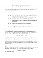
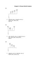
•13–1. The casting has a mass of 3 Mg. Suspended in a
vertical position and initially at rest, it is given an upward
speed of 200 mm> s in 0.3 s using a crane hook H. Determine
the tension in cables AC and AB during this time interval if
the acceleration is constant.
H
A
Kinematics: Applying the equation y = y0 + ac t, we have
(+ c )
0.2 = 0 + a(0.3)
30Њ
Equations of Motion:
+ ©F = ma ;
:
x
x
30Њ
a = 0.6667 m>s2
B
C
FAB sin 30 - FAC sin 30° = 0
FAB = FAC = F
+ c ©Fy = may ;
2Fcos 30° - 29430 = 3000(0.6667)
FAB = FAC = F = 18146.1 N = 18.1 kN
Ans.
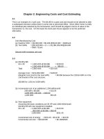
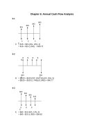
13–2. The 160-Mg train travels with a speed of 80 km>h
when it starts to climb the slope. If the engine exerts a
traction force F of 1>20 of the weight of the train and the
rolling resistance FD is equal to 1>500 of the weight of the
train, determine the deceleration of the train.
F
1
10
Free-Body Diagram: The tractive force and rolling resistance indicated on the free1
body diagram of the train, Fig. (a), are F = a b(160)(103)(9.81) N = 78 480 N and
20
1
3
FD = a
b (160)(10 )(9.81)N = 3139.2 N, respectively.
500
Equations of Motion: Here, the acceleration a of the train will be assumed to be
directed up the slope. By referring to Fig. (a),
+Q©Fx¿ = max¿ ;
78 480 - 3139.2 - 160(103)(9.81) ¢
1
2101
a = -0.5057 m>s2
≤ = 160(103)a
Ans.
177
91962_02_s13_p0177-0284
6/8/09
10:00 AM
Page 178
© 2010 Pearson Education, Inc., Upper Saddle River, NJ. All rights reserved. This material is protected under all copyright laws as they currently
exist. No portion of this material may be reproduced, in any form or by any means, without permission in writing from the publisher.
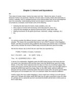
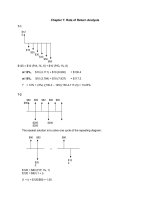
13–3. The 160-Mg train starts from rest and begins to
climb the slope as shown. If the engine exerts a traction
force F of 1>8 of the weight of the train, determine the
speed of the train when it has traveled up the slope a
distance of 1 km. Neglect rolling resistance.
F
1
10
Free-Body Diagram: Here, the tractive force indicated on the free-body diagram of
1
the train, Fig. (a), is F = (160)(103)(9.81) N = 196.2(103) N.
8
Equations of Motion: Here, the acceleration a of the train will be assumed directed
up the slope. By referring to Fig. (a),
+Q©Fx¿ = max¿ ;
196.2(103) - 160(103)(9.81)a
1
2101
b = 160(103)a
a = 0.2501 m>s2
Kinematics: Using the result of a,
A +Q B
v2 = v0 2 + 2ac(s - s0)
v2 = 0 + 2(0.2501)(1000 - 0)
v = 22.4 m>s
Ans.
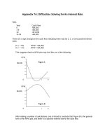
*13–4. The 2-Mg truck is traveling at 15 m> s when the
brakes on all its wheels are applied, causing it to skid for a
distance of 10 m before coming to rest. Determine the constant
horizontal force developed in the coupling C, and the frictional
force developed between the tires of the truck and the road
during this time. The total mass of the boat and trailer is 1 Mg.
C
Kinematics: Since the motion of the truck and trailer is known, their common
acceleration a will be determined first.
+ b
a:
v2 = v0 2 + 2ac(s - s0)
0 = 152 + 2a(10 - 0)
a = -11.25 m>s2 = 11.25 m>s2 ;
Free-Body Diagram: The free-body diagram of the truck and trailer are shown in
Figs. (a) and (b), respectively. Here, F representes the frictional force developed
when the truck skids, while the force developed in coupling C is represented by T.
Equations of Motion: Using the result of a and referrning to Fig. (a),
+ ©F = ma ;
:
x
x
-T = 1000(-11.25)
T = 11 250 N = 11.25 kN
Ans.
Using the results of a and T and referring to Fig. (b),
+ c ©Fx = max ;
11 250 - F = 2000(-11.25)
F = 33 750 N = 33.75 kN
Ans.
178
91962_02_s13_p0177-0284
6/8/09
10:00 AM
Page 179
© 2010 Pearson Education, Inc., Upper Saddle River, NJ. All rights reserved. This material is protected under all copyright laws as they currently
exist. No portion of this material may be reproduced, in any form or by any means, without permission in writing from the publisher.
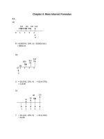
•13–5. If blocks A and B of mass 10 kg and 6 kg,
respectively, are placed on the inclined plane and released,
determine the force developed in the link. The coefficients
of kinetic friction between the blocks and the inclined plane
are mA = 0.1 and mB = 0.3. Neglect the mass of the link.
A
B
30Њ
Free-Body Diagram: Here, the kinetic friction (Ff)A = mANA = 0.1NA and
(Ff)B = mB NB = 0.3NB are required to act up the plane to oppose the motion of
the blocks which are down the plane. Since the blocks are connected, they have a
common acceleration a.
Equations of Motion: By referring to Figs. (a) and (b),
+Q©Fy¿ = may¿ ;
NA - 10(9.81) cos 30° = 10(0)
NA = 84.96 N
R+ ©Fx¿ = max¿ ;
10(9.81) sin 30° - 0.1(84.96) - F = 10a
40.55 - F = 10a
(1)
and
+Q©Fy¿ = may¿ ;
NB - 6(9.81) cos 30° = 6(0)
NB = 50.97 N
R+ ©Fx¿ = max¿ ;
F + 6(9.81) sin 30° - 0.3(50.97) = 6a
F + 14.14 = 6a
(2)
Solving Eqs. (1) and (2) yields
a = 3.42 m>s2
F = 6.37 N
Ans.
179
91962_02_s13_p0177-0284
6/8/09
10:00 AM
Page 180
© 2010 Pearson Education, Inc., Upper Saddle River, NJ. All rights reserved. This material is protected under all copyright laws as they currently
exist. No portion of this material may be reproduced, in any form or by any means, without permission in writing from the publisher.
13–6. Motors A and B draw in the cable with the
accelerations shown. Determine the acceleration of the
300-lb crate C and the tension developed in the cable.
Neglect the mass of all the pulleys.
C
aP¿ ϭ 2 ft/s2
B
P¿
Kinematics: We can express the length of the cable in terms of sP, sP¿, and sC by
referring to Fig. (a).
sP + sP¿ + 2sC = l
The second time derivative of the above equation gives
A+TB
aP + aP¿ + 2aC = 0
(1)
Here, aP = 3 ft>s2 and aP¿ = 2 ft>s2. Substituting these values into Eq. (1),
3 + 2 + 2aC = 0
aC = -2.5 ft>s2 = 2.5 ft>s2 c
Ans.
Free-Body Diagram: The free-body diagram of the crate is shown in Fig. (b).
Equations of Motion: Using the result of aC and referring to Fig. (b),
+ c ©Fy = may ;
2T - 300 =
300
(2.5)
32.2
T = 162 lb
Ans.
180
aP ϭ 3 ft/s2
P
A
91962_02_s13_p0177-0284
6/8/09
10:00 AM
Page 181
© 2010 Pearson Education, Inc., Upper Saddle River, NJ. All rights reserved. This material is protected under all copyright laws as they currently
exist. No portion of this material may be reproduced, in any form or by any means, without permission in writing from the publisher.
13–7. The van is traveling at 20 km> h when the coupling
of the trailer at A fails. If the trailer has a mass of 250 kg and
coasts 45 m before coming to rest, determine the constant
horizontal force F created by rolling friction which causes
the trailer to stop.
20 km/h
A
F
20 km>h =
+ b
a;
20(103)
= 5.556 m>s
3600
y2 = y20 + 2ac (s - s0)
0 = 5.5562 + 2(a)(45 - 0)
a = -0.3429 m>s2 = 0.3429 m>s2 :
+ ©F = ma ;
:
x
x
F = 250(0.3429) = 85.7 N
Ans.
181
91962_02_s13_p0177-0284
6/8/09
10:00 AM
Page 182
© 2010 Pearson Education, Inc., Upper Saddle River, NJ. All rights reserved. This material is protected under all copyright laws as they currently
exist. No portion of this material may be reproduced, in any form or by any means, without permission in writing from the publisher.
*13–8. If the 10-lb block A slides down the plane with a
constant velocity when u = 30°, determine the acceleration
of the block when u = 45°.
A
B
u
Free-Body Diagram: The free-body diagrams of the block when u = 30° and
u = 45° are shown in Figs. (a) and (b), respectively. Here, the kinetic friction
Ff = mkN and Ff¿ = mkN¿ are required to act up the plane to oppose the motion of
the block which is directed down the plane for both cases.
Equations of Motion: Since the block has constant velocity when u = 30°,
ax¿ = a = 0. Also, ay¿ = 0. By referring to Fig. (a), we can write
+Q©Fy¿ = may¿;
N - 10 cos 30° =
10
(0)
32.2
N = 8.660 lb
R+ ©Fx¿ = max¿ ;
10 sin 30° - mk(8.660) =
10
(0)
32.2
mk = 0.5774
Using the results of mk and referring to Fig. (b),
+Q©Fy¿ = may¿ ;
N¿ - 10 cos 45° =
10
(0)
32.2
N¿ = 7.071 lb
R+ ©Fx¿ = max¿ ;
10 sin 45° - 0.5774(7.071) =
10
a
32.2
a = 9.62 ft>s2
Ans.
182
C
91962_02_s13_p0177-0284
6/8/09
10:00 AM
Page 183
© 2010 Pearson Education, Inc., Upper Saddle River, NJ. All rights reserved. This material is protected under all copyright laws as they currently
exist. No portion of this material may be reproduced, in any form or by any means, without permission in writing from the publisher.
•13–9. Each of the three barges has a mass of 30 Mg,
whereas the tugboat has a mass of 12 Mg. As the barges are
being pulled forward with a constant velocity of 4 m> s, the
tugboat must overcome the frictional resistance of the water,
which is 2 kN for each barge and 1.5 kN for the tugboat. If the
cable between A and B breaks, determine the acceleration of
the tugboat.
4 m/s
A B
2 kN
2 kN
2 kN
1.5 kN
Equations of Motion: When the tugboat and barges are travelling at a constant
velocity, the driving force F can be determined by applying Eq. 13–7.
+ ©F = ma ;
:
x
x
F - 1.5 - 2 - 2 = 0
F = 7.50 kN
If the cable between barge A and B breaks and the driving force F remains the
same, the acceleration of the tugboat and barge is given by
+ ©F = ma ;
:
x
x
(7.50 - 1.5 - 2 - 2) A 103 B = (12 000 + 30 000 + 3000)a
a = 0.0278 m>s2
Ans.
13–10. The crate has a mass of 80 kg and is being towed by
a chain which is always directed at 20° from the horizontal
as shown. If the magnitude of P is increased until the crate
begins to slide, determine the crate’s initial acceleration if
the coefficient of static friction is ms = 0.5 and the
coefficient of kinetic friction is mk = 0.3.
p
20Њ
Equations of Equilibrium: If the crate is on the verge of slipping, Ff = ms N = 0.5N.
From FBD(a),
+ c ©Fy = 0;
N + P sin 20° - 80(9.81) = 0
(1)
+ ©F = 0;
:
x
P cos 20° - 0.5N = 0
(2)
Solving Eqs.(1) and (2) yields
P = 353.29 N
N = 663.97 N
Equations of Motion: The friction force developed between the crate and its
contacting surface is Ff = mkN = 0.3N since the crate is moving. From FBD(b),
+ c ©Fy = may ;
N - 80(9.81) + 353.29 sin 20° = 80(0)
N = 663.97 N
+ ©F = ma ;
:
x
x
353.29 cos 20° - 0.3(663.97) = 80a
a = 1.66 m>s2
Ans.
183
91962_02_s13_p0177-0284
6/8/09
10:00 AM
Page 184
© 2010 Pearson Education, Inc., Upper Saddle River, NJ. All rights reserved. This material is protected under all copyright laws as they currently
exist. No portion of this material may be reproduced, in any form or by any means, without permission in writing from the publisher.
13–11. The crate has a mass of 80 kg and is being towed by
a chain which is always directed at 20° from the horizontal
as shown. Determine the crate’s acceleration in t = 2 s if
the coefficient of static friction is ms = 0.4, the coefficient of
kinetic friction is mk = 0.3, and the towing force is
P = (90t2) N, where t is in seconds.
p
20Њ
Equations of Equilibrium: At t = 2 s, P = 90 A 22 B = 360 N. From FBD(a)
+ c ©Fy = 0;
N + 360 sin 20° - 80(9.81) = 0
+ ©F = 0;
:
x
360 cos 20° - Ff = 0
N = 661.67 N
Ff = 338.29N
Since Ff 7 (Ff)max = ms N = 0.4(661.67) = 264.67 N, the crate accelerates.
Equations of Motion: The friction force developed between the crate and its
contacting surface is Ff = mkN = 0.3N since the crate is moving. From FBD(b),
+ c ©Fy = may ;
N - 80(9.81) + 360 sin 20° = 80(0)
N = 661.67 N
+ ©F = ma ;
:
x
x
360 cos 20° - 0.3(661.67) = 80a
a = 1.75 m>s2
Ans.
184
91962_02_s13_p0177-0284
6/8/09
10:00 AM
Page 185
© 2010 Pearson Education, Inc., Upper Saddle River, NJ. All rights reserved. This material is protected under all copyright laws as they currently
exist. No portion of this material may be reproduced, in any form or by any means, without permission in writing from the publisher.
*13–12. Determine the acceleration of the system and the
tension in each cable. The inclined plane is smooth, and the
coefficient of kinetic friction between the horizontal surface
and block C is (mk)C = 0.2.
E
A
25 kg
B
5 kg
D
30Њ
C
(mk)C ϭ 0.2
Free-Body Diagram: The free-body diagram of block A, cylinder B, and block C are
shown in Figs. (a), (b), and (c), respectively. The frictional force
(Ff)C = (mk)C NC = 0.2NC must act to the right to oppose the motion of block C
which is to the left.
Equations of Motion: Since block A, cylinder B, and block C move together as a
single unit, they share a common acceleration a. By referring to Figs. (a), (b), and (c),
©Fx¿ = max¿ ;
T1 - 25(9.81) sin 30° = 25(-a)
(1)
and
+ c ©Fy = may ;
T1 - T2 - 5(9.81) = 5(a)
(2)
and
+ c ©Fy = may ;
NC - 10(9.81) = 10(0)
NC = 98.1 N
+ ©F = ma ;
:
x
x
(3)
-T2 + 0.2(98.1) = 10( -a)
Solving Eqs. (1), (2), and (3), yields
a = 1.349 m>s2
T1 = 88.90 N = 88.9N
Ans.
T2 = 33.11 N = 33.1 N
Ans.
185
10 kg
91962_02_s13_p0177-0284
6/8/09
10:00 AM
Page 186
© 2010 Pearson Education, Inc., Upper Saddle River, NJ. All rights reserved. This material is protected under all copyright laws as they currently
exist. No portion of this material may be reproduced, in any form or by any means, without permission in writing from the publisher.
•13–13. The two boxcars A and B have a weight of 20 000 lb
and 30 000 lb, respectively. If they coast freely down the
incline when the brakes are applied to all the wheels of car A
causing it to skid, determine the force in the coupling C
between the two cars. The coefficient of kinetic friction
between the wheels of A and the tracks is mk = 0.5. The
wheels of car B are free to roll. Neglect their mass in the
calculation. Suggestion: Solve the problem by representing
single resultant normal forces acting on A and B, respectively.
5Њ
C
Car A:
+a©Fy
= 0;
+Q©Fx = max ;
NA - 20 000 cos 5° = 0
NA = 19 923.89 lb
0.5(19 923.89) - T - 20 000 sin 5° = a
20 000
ba
32.2
(1)
Both cars:
+Q©Fx = max ;
0.5(19 923.89) - 50 000 sin 5° = a
B
A
50 000
ba
32.2
Solving,
a = 3.61 ft>s2
T = 5.98 kip
Ans.
186
91962_02_s13_p0177-0284
6/8/09
10:00 AM
Page 187
© 2010 Pearson Education, Inc., Upper Saddle River, NJ. All rights reserved. This material is protected under all copyright laws as they currently
exist. No portion of this material may be reproduced, in any form or by any means, without permission in writing from the publisher.
13–14. The 3.5-Mg engine is suspended from a spreader
beam AB having a negligible mass and is hoisted by a
crane which gives it an acceleration of 4 m>s2 when it has
a velocity of 2 m> s. Determine the force in chains CA and
CB during the lift.
C
60Њ
60Њ
B
A
System:
+ c ©Fy = may ;
E
D
T¿ - 3.5 A 103 B (9.81) = 3.5 A 103 B (4)
T¿ = 48.335 kN
Joint C:
+ c ©Fy = may ;
48.335 - 2 T cos 30° = 0
T = TCA = TCB = 27.9 kN
Ans.
13–15. The 3.5-Mg engine is suspended from a spreader
beam having a negligible mass and is hoisted by a crane
which exerts a force of 40 kN on the hoisting cable.
Determine the distance the engine is hoisted in 4 s, starting
from rest.
C
60Њ
A
60Њ
B
System:
+ c ©Fy = may ;
D
40 A 103 B - 3.5 A 103 B (9.81) = 3.5 A 103 B a
a = 1.619 m>s2
A+cB
s = s0 + y0 t +
s = 0 + 0 +
1
a t2
2 c
1
(1.619)(4)2 = 12.9 m
2
Ans.
187
E
91962_02_s13_p0177-0284
6/8/09
10:00 AM
Page 188
© 2010 Pearson Education, Inc., Upper Saddle River, NJ. All rights reserved. This material is protected under all copyright laws as they currently
exist. No portion of this material may be reproduced, in any form or by any means, without permission in writing from the publisher.
*13–16. The man pushes on the 60-lb crate with a force F.
The force is always directed down at 30° from the
horizontal as shown, and its magnitude is increased until the
crate begins to slide. Determine the crate’s initial
acceleration if the coefficient of static friction is ms = 0.6
and the coefficient of kinetic friction is mk = 0.3.
F
30Њ
Force to produce motion:
+ ©F = 0;
:
x
Fcos 30° - 0.6N = 0
+ c ©Fy = 0;
N - 60 - F sin 30° = 0
N = 91.80 lb
F = 63.60 lb
Since N = 91.80 lb,
+ ©F = ma ;
:
x
x
63.60 cos 30° - 0.3(91.80) = a
60
ba
32.2
a = 14.8 ft>s2
Ans.
188
91962_02_s13_p0177-0284
6/8/09
10:00 AM
Page 189
© 2010 Pearson Education, Inc., Upper Saddle River, NJ. All rights reserved. This material is protected under all copyright laws as they currently
exist. No portion of this material may be reproduced, in any form or by any means, without permission in writing from the publisher.
•13–17. A force of F = 15 lb is applied to the cord.
Determine how high the 30-lb block A rises in 2 s starting
from rest. Neglect the weight of the pulleys and cord.
C
B
F
Block:
+ c ©Fy = may ;
-30 + 60 = a
30
ba
32.2 A
aA = 32.2 ft>s2
(+ c )
s = s0 + y0 t +
s = 0 + 0 +
1
a t2
2 c
1
(32.2)(2)2
2
s = 64.4 ft
Ans.
189
A
91962_02_s13_p0177-0284
6/8/09
10:00 AM
Page 190
© 2010 Pearson Education, Inc., Upper Saddle River, NJ. All rights reserved. This material is protected under all copyright laws as they currently
exist. No portion of this material may be reproduced, in any form or by any means, without permission in writing from the publisher.
13–18. Determine the constant force F which must be
applied to the cord in order to cause the 30-lb block A to
have a speed of 12 ft/s when it has been displaced 3 ft
upward starting from rest. Neglect the weight of the pulleys
and cord.
C
B
A+cB
F
y2 = y20 + 2ac (s - s0)
(12)2 = 0 + 2(a)(3)
a = 24 ft>s2
+ c ©Fy = may ;
- 30 + 4F = a
30
b(24)
32.2
F = 13.1 lb
Ans.
190
A
91962_02_s13_p0177-0284
6/8/09
10:00 AM
Page 191
© 2010 Pearson Education, Inc., Upper Saddle River, NJ. All rights reserved. This material is protected under all copyright laws as they currently
exist. No portion of this material may be reproduced, in any form or by any means, without permission in writing from the publisher.
13–19. The 800-kg car at B is connected to the 350-kg car
at A by a spring coupling. Determine the stretch in the
spring if (a) the wheels of both cars are free to roll and
(b) the brakes are applied to all four wheels of
car B, causing the wheels to skid. Take (mk)B = 0.4. Neglect
the mass of the wheels.
B
k ϭ 600 N/m
A
5
a) Equations of Motion: Applying Eq. 13–7 to FBD(a), we have
R+ ©Fx¿ = max¿ ;
4
3
(800 + 350)(9.81) sin 53.13° = (800 + 350)a
a = 7.848 m>s2
For FBD(b),
R+ ©Fx¿ = max¿ ;
350(9.81) sin 53.13° + Fsp = 350(7.848)
Fsp = 0
The stretch of spring is given by
x =
Fsp
k
Ans.
= 0
b) Equations of Motion: The friction force developed between the wheels of car B
and the inclined plane is (Ff)B = (mk)B NB = 0.4NB. For car B only [FBD(c)],
+Q©Fy¿ = may¿ ;
NB - 800(9.81) cos 53.13° = 800(0)
NB = 4708.8 N
For the whole system (FBD(c)],
R+ ©Fx¿ = max¿ ;
(800 + 350)(9.81) sin 53.13° - 0.4(4708.8) = (800 + 350)a
a = 6.210 m>s2
For FBD(b),
R+ ©Fx¿ = max¿ ;
350(9.81) sin 53.13° - Fsp = 350 (6.210)
Fsp = 573.25 N
The stretch of spring is given by
x =
Fsp
k
=
573.25
= 0.955 m
600
Ans.
191
91962_02_s13_p0177-0284
6/8/09
10:01 AM
Page 192
© 2010 Pearson Education, Inc., Upper Saddle River, NJ. All rights reserved. This material is protected under all copyright laws as they currently
exist. No portion of this material may be reproduced, in any form or by any means, without permission in writing from the publisher.
*13–20. The 10-lb block A travels to the right at
vA = 2 ft>s at the instant shown. If the coefficient of kinetic
friction is mk = 0.2 between the surface and A, determine
the velocity of A when it has moved 4 ft. Block B has a
weight of 20 lb.
A
B
Block A:
+ ©F = ma ;
;
x
x
-T + 2 = a
10
ba
32.2 A
(1)
Weight B:
+ T ©Fy = may ;
20 - 2T = a
20
ba
32.2 B
(2)
Kinematics:
sA + 2sB = l
aA = -2aB
(3)
Solving Eqs. (1)–(3):
aA = -17.173 ft>s2
aB = 8.587 ft>s2
T = 7.33 lb
y2 = y20 + 2ac (s - s0)
y2 = (2)2 + 2(17.173)(4 - 0)
y = 11.9 ft>s
Ans.
192
91962_02_s13_p0177-0284
6/8/09
10:01 AM
Page 193
© 2010 Pearson Education, Inc., Upper Saddle River, NJ. All rights reserved. This material is protected under all copyright laws as they currently
exist. No portion of this material may be reproduced, in any form or by any means, without permission in writing from the publisher.
•13–21. Block B has a mass m and is released from rest
when it is on top of cart A, which has a mass of 3m.
Determine the tension in cord CD needed to hold the cart
from moving while B slides down A. Neglect friction.
B
D
C
Block B:
+a©Fy = may ;
A
u
NB - mg cos u = 0
NB = mg cos u
Cart:
+ ©F = ma ;
:
x
x
-T + NB sin u = 0
T = mg sin u cos u
T = a
mg
b sin 2u
2
Ans.
13–22. Block B has a mass m and is released from rest
when it is on top of cart A, which has a mass of 3m.
Determine the tension in cord CD needed to hold the cart
from moving while B slides down A. The coefficient of
kinetic friction between A and B is mk.
B
D
Block B:
+a©Fy = may ;
NB - mg cos u = 0
NB = mg cos u
Cart:
+ ©F = ma ;
:
x
x
-T + NB sin u - mk NB cos u = 0
T = mg cos u(sin u - mk cos u)
Ans.
193
C
u
A
91962_02_s13_p0177-0284
6/8/09
10:01 AM
Page 194
© 2010 Pearson Education, Inc., Upper Saddle River, NJ. All rights reserved. This material is protected under all copyright laws as they currently
exist. No portion of this material may be reproduced, in any form or by any means, without permission in writing from the publisher.
13–23. The 2-kg shaft CA passes through a smooth journal
bearing at B. Initially, the springs, which are coiled loosely
around the shaft, are unstretched when no force is applied
to the shaft. In this position s = s¿ = 250 mm and the shaft
is at rest. If a horizontal force of F = 5 kN is applied,
determine the speed of the shaft at the instant s = 50 mm,
s¿ = 450 mm. The ends of the springs are attached to the
bearing at B and the caps at C and A.
FCB = kCBx = 3000x
+ ©F = ma ;
;
x
x
s¿
C
B
kCB ϭ 3 kN/m
FAB = kABx = 2000x
5000 - 3000x - 2000x = 2a
2500 - 2500x = a
a dx - v dv
0.2
L0
v
(2500 - 2500x) dx =
2500(0.2) - ¢
L0
v dv
2500(0.2)2
v2
≤ =
2
2
v = 30 m>s
Ans.
194
s
A
kAB ϭ 2 kN/m
F ϭ 5 kN
91962_02_s13_p0177-0284
6/8/09
10:01 AM
Page 195
© 2010 Pearson Education, Inc., Upper Saddle River, NJ. All rights reserved. This material is protected under all copyright laws as they currently
exist. No portion of this material may be reproduced, in any form or by any means, without permission in writing from the publisher.
*13–24. If the force of the motor M on the cable is
shown in the graph, determine the velocity of the cart
when t = 3 s. The load and cart have a mass of 200 kg and
the car starts from rest.
F (N)
450
Free-Body Diagram: The free-body diagram of the rail car is shown in Fig. (a).
t (s)
450
t = A 150t B N. By referring to Fig. (a),
Equations of Motion: For 0 … t 6 3 s, F =
3
we can write
+Q©Fx¿ = max¿ ;
a = (2.25t - 4.905) m>s2
30Њ
For t 7 3 s, F = 450 N. Thus,
3(450) - 200(9.81) sin 30° = 200a
a = 1.845 m>s2
Equilibrium: For the rail car to move, force 3F must overcome the weight
component of the rail crate. Thus, the time required to move the rail car is given by
©Fx¿ = 0; 3(150t) - 200(9.81) sin 30° = 0
t = 2.18 s
Kinematics: The velocity of the rail car can be obtained by integrating the kinematic
equation, dv = adt. For 2.18 s … t 6 3 s, v = 0 at t = 2.18 s will be used as the
integration limit. Thus,
A+cB
L
dy =
t
y
L0
adt
L
dy =
L2.18 s
(2.25t - 4.905)dt
y = A 1.125t2 - 4.905t B 2
M
F
C
3(150t) - 200(9.81) sin 30° = 200a
+Q©Fx¿ = max¿ ;
3
t
2.18 s
= A 1.125t2 - 4.905t + 5.34645 B m>s
When t = 3 s,
y = 1.125(3)2 - 4.905(3) + 5.34645 = 0.756m>s
Ans.
195
91962_02_s13_p0177-0284
6/8/09
10:01 AM
Page 196
© 2010 Pearson Education, Inc., Upper Saddle River, NJ. All rights reserved. This material is protected under all copyright laws as they currently
exist. No portion of this material may be reproduced, in any form or by any means, without permission in writing from the publisher.
•13–25. If the motor draws in the cable with an
acceleration of 3 m>s2, determine the reactions at the
supports A and B. The beam has a uniform mass of 30 kg> m,
and the crate has a mass of 200 kg. Neglect the mass of the
motor and pulleys.
+R©Ft = mat ;
mg sin u = mat
y dy = at ds = g sin u ds
B
3 m/s2
at = g sin u
However dy = ds sin u
y dy =
L0
g dy
C
y = 22gh
Q.E.D.
13–26. A freight elevator, including its load, has a mass of
500 kg. It is prevented from rotating by the track and wheels
mounted along its sides. When t = 2 s, the motor M draws in
the cable with a speed of 6 m> s, measured relative to the
elevator. If it starts from rest, determine the constant
acceleration of the elevator and the tension in the cable.
Neglect the mass of the pulleys, motor, and cables.
M
3sE + sP = l
3yE = -yP
yP = yE + yP>E
-3yE = yE + 6
yE = -
A+cB
3m
A
y2
= gh
2
A+TB
0.5 m
h
y
L0
2.5 m
6
= -1.5 m>s = 1.5 m>s c
4
y = y0 + ac t
1.5 = 0 + aE (2)
aE = 0.75 m>s2 c
+ c ©Fy = may ;
Ans.
4T - 500(9.81) = 500(0.75)
T = 1320 N = 1.32 kN
Ans.
196
91962_02_s13_p0177-0284
6/8/09
10:01 AM
Page 197
© 2010 Pearson Education, Inc., Upper Saddle River, NJ. All rights reserved. This material is protected under all copyright laws as they currently
exist. No portion of this material may be reproduced, in any form or by any means, without permission in writing from the publisher.
13–27. Determine the required mass of block A so that
when it is released from rest it moves the 5-kg block B a
distance of 0.75 m up along the smooth inclined plane in
t = 2 s. Neglect the mass of the pulleys and cords.
E
C
D
B
Kinematic: Applying equation s = s0 + y0 t +
(a+)
0.75 = 0 + 0 +
1
a A 22 B
2 B
1
a t2, we have
2 c
A
60Њ
aB = 0.375 m>s2
Establishing the position - coordinate equation, we have
2sA + (sA - sB) = l
3sA - sB = l
Taking time derivative twice yields
3aA - aB = 0
(1)
From Eq.(1),
3aA - 0.375 = 0
aA = 0.125 m>s2
Equation of Motion: The tension T developed in the cord is the same throughout
the entire cord since the cord passes over the smooth pulleys. From FBD(b),
a + ©Fy¿ = may¿ ;
T - 5(9.81) sin 60° = 5(0.375)
T = 44.35 N
From FBD(a),
+ c ©Fy = may ;
3(44.35) - 9.81mA = mA (-0.125)
mA = 13.7 kg
Ans.
197
91962_02_s13_p0177-0284
6/8/09
10:01 AM
Page 198
© 2010 Pearson Education, Inc., Upper Saddle River, NJ. All rights reserved. This material is protected under all copyright laws as they currently
exist. No portion of this material may be reproduced, in any form or by any means, without permission in writing from the publisher.
*13–28. Blocks A and B have a mass of mA and mB, where
mA > mB. If pulley C is given an acceleration of a0, determine
the acceleration of the blocks. Neglect the mass of the pulley.
a0
C
Free-Body Diagram: The free-body diagram of blocks A and B are shown in
Figs, (a) and (b), respectively. Here, aA and aB are assumed to be directed
upwards. Since pulley C is smooth, the tension in the cord remains constant for
the entire cord.
Equations of Motion: By referring to Figs. (a) and (b),
+ c ©Fy = may ;
A
T - mA g = mAaA
(1)
T - mB g = mB aB
(2)
and
+ c ©Fy = may ;
Eliminating T from Eqs. (1) and (2) yields
(mA - mB)g = mB aB - mA aA
(3)
Kinematics: The acceleration of blocks A and B relative to pulley C will be of the
same magnitude, i.e., aA>C = aB>C = arel. If we assume that aA/C is directed
downwards, aB/C must also be directed downwards to be consistent. Applying the
relative acceleration equation,
A+cB
aA = aC + aA>C
aA = aO - arel
(4)
and
A+cB
B
aB = aC + aB>C
aB = aO - arel
(5)
Eliminating arel from Eqs.(4) and (5),
aA + aB = 2aO
(6)
Solving Eqs. (3) and (6), yields
aA =
2mg aO - (mA - mB)g
mA + mB
c
Ans.
aB =
2mAaO + (mA - mB)g
mA + mB
c
Ans.
198
91962_02_s13_p0177-0284
6/8/09
10:01 AM
Page 199
© 2010 Pearson Education, Inc., Upper Saddle River, NJ. All rights reserved. This material is protected under all copyright laws as they currently
exist. No portion of this material may be reproduced, in any form or by any means, without permission in writing from the publisher.
•13–29. The tractor is used to lift the 150-kg load B with
the 24-m-long rope, boom, and pulley system. If the tractor
travels to the right at a constant speed of 4 m> s, determine
the tension in the rope when sA = 5 m. When sA = 0,
sB = 0.
12 m
sB
12 - sB + 2s2A + (12)2 = 24
B
1
#
-sB + A s2A + 144 B - 2 asAsA b = 0
$
-sB - A s2A + 144 B
$
sB = - C
aB = - C
A
sA
#
asAsA b + A s2A + 144 B
2
- 32
#
s2As2A
$
#
s2A + sAsA
A s2A + 144 B 2
-
3
(5)2(4)2
A s2A + 144 B 2
1
-
((5)2 + 144)
+ c ©Fy = may ;
#
as2A b + A s2A + 144 B
- 12
$
asA sA b = 0
S
(4)2 + 0
3
2
- 12
1
((5)2 + 144)2
S = 1.0487 m>s2
T - 150(9.81) = 150(1.0487)
T = 1.63 kN
Ans.
13–30. The tractor is used to lift the 150-kg load B with the
24-m-long rope, boom, and pulley system. If the tractor
travels to the right with an acceleration of 3 m>s2 and has a
velocity of 4 m> s at the instant sA = 5 m, determine the
tension in the rope at this instant. When sA = 0, sB = 0.
12 m
sB
12 = sB + 2s2A + (12)2 = 24
B
A
3
1
#
#
-sB + A s2A + 144 B - 2 a2sA sA b = 0
2
sA
3
1
1
#
#
$
$
-sB - A s2A + 144 B - 2 asAsA b + A s2A + 144 B - 2 as2A b + A s2A + 144 B - 2 asAsA b = 0
2
$
sB = - C
aB = - C
#
s2A s2A
$
#
s2A + sA sA
A s2A + 144 B 2
-
3
(5)2(4)2
1
S
(4)2 + (5)(3)
3
2
((5)2 + 144)
+ c ©Fy = may ;
A s2A + 144 B 2
-
1
((5)2 + 144)2
S = 2.2025 m>s2
T - 150(9.81) = 150(2.2025)
T = 1.80 kN
Ans.
199
91962_02_s13_p0177-0284
6/8/09
10:01 AM
Page 200
© 2010 Pearson Education, Inc., Upper Saddle River, NJ. All rights reserved. This material is protected under all copyright laws as they currently
exist. No portion of this material may be reproduced, in any form or by any means, without permission in writing from the publisher.
13–31. The 75-kg man climbs up the rope with an
acceleration of 0.25 m>s2, measured relative to the rope.
Determine the tension in the rope and the acceleration of
the 80-kg block.
A
Free-Body Diagram: The free-body diagram of the man and block A are shown in
Figs. (a) and (b), respectively. Here, the acceleration of the man am and the block aA
are assumed to be directed upwards.
Equations of Motion: By referring to Figs. (a) and (b),
+ c ©Fy = may ;
T - 75(9.81) = 75am
(1)
and
+ c ©Fy = may ;
T - 80(9.81) = 80aA
(2)
Kinematics: Here, the rope has an acceleration with a magnitude equal to that of
block A, i.e., ar = aA and is directed downward. Applying the relative acceleration
equation,
A+cB
am = ar + am>r
am = -aA + 0.25
(3)
Solving Eqs. (1), (2), and (3) yields
aA = -0.19548 m>s2 = 0.195 m>s2 T
Ans.
T = 769.16 N = 769 N
Ans.
am = 0.4455 m>s2
200
B
91962_02_s13_p0177-0284
6/8/09
10:01 AM
Page 201
© 2010 Pearson Education, Inc., Upper Saddle River, NJ. All rights reserved. This material is protected under all copyright laws as they currently
exist. No portion of this material may be reproduced, in any form or by any means, without permission in writing from the publisher.
*13–32. Motor M draws in the cable with an acceleration
of 4 ft>s2, measured relative to the 200-lb mine car.
Determine the acceleration of the car and the tension in the
cable. Neglect the mass of the pulleys.
aP/c ϭ 4 ft/s2
P
M
30Њ
Free-Body Diagram: The free-body diagram of the mine car is shown in Fig. (a).
Here, its acceleration aC is assumed to be directed down the inclined plane so that it
is consistent with the position coordinate sC of the mine car as indicated on Fig. (b).
Equations of Motion: By referring to Fig. (a),
+Q©Fx¿ = max¿ ;
3T - 200 sin 30° =
200
( -aC)
32.2
(1)
Kinematics: We can express the length of the cable in terms of sP and sC by referring
to Fig. (b).
sP + 2sC = 0
The second derivative of the above equation gives
aP + 2aC = 0
(2)
Applying the relative acceleration equation,
aP = aC + a P>C
aP = aC + 4
(3)
Solving Eqs. (1), (2), and (3) yields
aC = -1.333 ft>s2 = 1.33 ft>s2
Ans.
T = 36.1 lb
Ans.
aP = 2.667 ft>s2
201