Solution manual mechanics of materials 8th edition hibbeler chapter 09
Bạn đang xem bản rút gọn của tài liệu. Xem và tải ngay bản đầy đủ của tài liệu tại đây (11.58 MB, 119 trang )
09 Solutions 46060
6/8/10
3:13 PM
Page 619
© 2010 Pearson Education, Inc., Upper Saddle River, NJ. All rights reserved. This material is protected under all copyright laws as they currently
exist. No portion of this material may be reproduced, in any form or by any means, without permission in writing from the publisher.
9–1. Prove that the sum of the normal stresses
sx + sy = sx¿ + sy¿ is constant. See Figs. 9–2a and 9–2b.
Stress Transformation Equations: Applying Eqs. 9-1 and 9-3 of the text.
sx¿ + sy¿ =
sx + sy
2
sx - sy
+
2
cos 2u + txy sin 2u
sx + sy
+
2
sx - sy
-
2
cos 2u - txy sin 2u
sx¿ + sy¿ = sx + sy
(Q.E.D.)
619
09 Solutions 46060
6/8/10
3:13 PM
Page 620
© 2010 Pearson Education, Inc., Upper Saddle River, NJ. All rights reserved. This material is protected under all copyright laws as they currently
exist. No portion of this material may be reproduced, in any form or by any means, without permission in writing from the publisher.
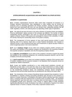
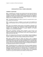
9–2. The state of stress at a point in a member is shown on
the element. Determine the stress components acting on
the inclined plane AB. Solve the problem using the method
of equilibrium described in Sec. 9.1.
A
8 ksi
2 ksi
5 ksi
60Њ
B
Referring to Fig a, if we assume that the areas of the inclined plane AB is ¢A, then
the area of the horizontal and vertical of the triangular element are ¢A cos 60° and
¢A sin 60° respectively. The forces act acting on these two faces indicated on the
FBD of the triangular element, Fig. b.
¢Fx¿ + 2¢A sin 60° cos 60° + 5¢ A sin 60° sin 60°
+Q©Fx¿ = 0;
+ 2¢A cos 60° sin 60° - 8¢A cos 60° cos 60° = 0
¢Fx¿ = -3.482 ¢A
¢Fy¿ + 2¢A sin 60° sin 60° - 5¢ A sin 60° cos 60°
+a©Fy¿ = 0;
- 8¢A cos 60° sin 60° - 2¢A cos 60° cos 60° = 0
¢Fy¿ = 4.629 ¢A
From the definition,
sx¿ = lim¢A:0
¢Fx¿
= -3.48 ksi
¢A
tx¿y¿ = lim¢A:0
¢Fy¿
Ans.
Ans.
= 4.63 ksi
¢A
The negative sign indicates that sx¿, is a compressive stress.
620
09 Solutions 46060
6/8/10
3:13 PM
Page 621
© 2010 Pearson Education, Inc., Upper Saddle River, NJ. All rights reserved. This material is protected under all copyright laws as they currently
exist. No portion of this material may be reproduced, in any form or by any means, without permission in writing from the publisher.
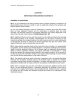
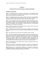
9–3. The state of stress at a point in a member is shown on
the element. Determine the stress components acting on
the inclined plane AB. Solve the problem using the method
of equilibrium described in Sec. 9.1.
500 psi
B
60Њ
A
Referring to Fig. a, if we assume that the area of the inclined plane AB is ¢A, then
the areas of the horizontal and vertical surfaces of the triangular element are
¢A sin 60° and ¢A cos 60° respectively. The force acting on these two faces are
indicated on the FBD of the triangular element, Fig. b
+R©Fx¿ = 0;
¢Fx¿ + 500 ¢A sin 60° sin 60° + 350¢A sin 60° cos 60°
+350¢A cos 60° sin 60° = 0
¢Fx¿ = -678.11 ¢A
+Q©Fy¿ = 0;
¢Fy¿ + 350¢A sin 60° sin 60° - 500¢A sin 60° cos 60°
-350¢A cos 60° cos 60° = 0
¢Fy¿ = 41.51 ¢A
From the definition
sx¿ = lim¢A:0
tx¿y¿ = lim¢A:0
¢Fx¿
= -6.78 psi
¢A
¢Fy¿
Ans.
Ans.
= 41.5 psi
¢A
The negative sign indicates that sx¿, is a compressive stress.
621
350 psi
09 Solutions 46060
6/8/10
3:13 PM
Page 622
© 2010 Pearson Education, Inc., Upper Saddle River, NJ. All rights reserved. This material is protected under all copyright laws as they currently
exist. No portion of this material may be reproduced, in any form or by any means, without permission in writing from the publisher.
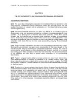
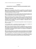
*9–4. The state of stress at a point in a member is shown
on the element. Determine the stress components acting on
the inclined plane AB. Solve the problem using the method
of equilibrium described in Sec. 9.1.
A
650 psi
¢Fx¿ - 400(¢Acos 60°)cos 60° + 650(¢ A sin 60°)cos 30° = 0
Q+ ©Fx¿ = 0
400 psi
60Њ
¢Fx¿ = -387.5¢A
¢Fy¿ - 650(¢Asin 60°)sin 30° - 400(¢ A cos 60°)sin 60° = 0
a+ ©Fy¿ = 0
B
¢Fy¿ = 455 ¢A
sx¿ = lim¢A:0
sx¿y¿ = lim¢A:0
¢Fx¿
= -388 psi
¢A
¢Fy¿
Ans.
Ans.
= 455 psi
¢A
The negative sign indicates that the sense of sx¿, is opposite to that shown on FBD.
•9–5.
Solve Prob. 9–4 using the stress-transformation
equations developed in Sec. 9.2.
sy = 400 psi
sx = -650 psi
sx¿ =
=
sx + sy
sx - sy
+
2
2
txy = 0
A
400 psi
u = 30°
650 psi
cos 2u + txy sin 2u
60Њ
-650 + 400
-650 - 400
+
cos 60° + 0 = -388 psi
2
2
Ans.
B
The negative sign indicates sx¿, is a compressive stress.
tx¿y¿ = = -a
sx - sy
2
sin 2u + txy cos 2u
-650 - 400
bsin 60° = 455 psi
2
Ans.
622
09 Solutions 46060
6/8/10
3:13 PM
Page 623
© 2010 Pearson Education, Inc., Upper Saddle River, NJ. All rights reserved. This material is protected under all copyright laws as they currently
exist. No portion of this material may be reproduced, in any form or by any means, without permission in writing from the publisher.
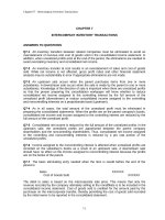
9–6. The state of stress at a point in a member is shown on
the element. Determine the stress components acting on
the inclined plane AB. Solve the problem using the method
of equilibrium described in Sec. 9.1.
90 MPa
A
35 MPa
60Њ
30Њ
R+ ©Fy¿ = 0
B
50 MPa
¢Fy¿ - 50¢A sin 30° cos 30° - 35¢A sin 30° cos 60° +
90¢A cos 30° sin 30° + 35¢A cos 30° sin 60° = 0
¢Fy¿ = -34.82¢A
b+ ©Fx¿ = 0
¢Fx¿ - 50¢A sin 30° sin 30° + 35¢A sin 30° sin 60°
-90¢A cos 30° cos 30° + 35¢A cos 30° cos 60° = 0
¢Fx¿ = 49.69 ¢A
sx¿ = lim¢A:0
¢Fx¿
= 49.7 MPa
¢A
tx¿y¿ = lim¢A:0
¢Fy¿
Ans.
Ans.
= -34.8 MPa
¢A
The negative signs indicate that the sense of sx¿, and tx¿y¿ are opposite to the shown
on FBD.
9–7. Solve Prob. 9–6 using the stress-transformation
equations developed in Sec. 9.2. Show the result on a sketch.
90 MPa
A
35 MPa
60Њ
30Њ
sy = 50 MPa
sx = 90 MPa
sx¿ =
=
sx + sy
sx - sy
+
2
2
txy = -35 MPa
u = -150°
cos 2u + txy sin 2u
90 - 50
90 + 50
+
cos(-300°) + (-35) sin ( -300°)
2
2
= 49.7 MPa
tx¿y¿ = -
sx - sy
= -a
2
Ans.
sin 2u + txy cos 2u
90 - 50
bsin(-300°) + ( -35) cos ( -300°) = -34.8 MPa
2
The negative sign indicates tx¿y¿ acts in -y¿ direction.
623
Ans.
B
50 MPa
09 Solutions 46060
6/8/10
3:13 PM
Page 624
© 2010 Pearson Education, Inc., Upper Saddle River, NJ. All rights reserved. This material is protected under all copyright laws as they currently
exist. No portion of this material may be reproduced, in any form or by any means, without permission in writing from the publisher.
*9–8. Determine the normal stress and shear stress acting
on the inclined plane AB. Solve the problem using the
method of equilibrium described in Sec. 9.1.
45 MPa
B
80 MPa
45Њ
A
Force Equllibrium: Referring to Fig. a, if we assume that the area of the inclined
plane AB is ¢A, then the area of the vertical and horizontal faces of the triangular
sectioned element are ¢A sin 45° and ¢A cos 45°, respectively. The forces acting on
the free-body diagram of the triangular sectioned element, Fig. b, are
©Fx¿ = 0;
¢Fx¿ + c45 A 106 B ¢A sin 45° dcos 45° + c45 A 106 B ¢A cos 45° dsin 45°
- c80 A 106 B ¢A sin 45° dcos 45° = 0
¢Fx¿ = -5 A 106 B ¢A
©Fy¿ = 0;
¢Fy¿ + c45 A 106 B ¢A cos 45° dcos 45° - c45 A 106 B ¢A sin 45° dsin 45°
- c80 A 106 B ¢ A sin 45° dsin 45° = 0
¢Fy¿ = 40 A 106 B ¢A
Normal and Shear Stress: From the definition of normal and shear stress,
sx¿ = lim¢A:0
¢Fx¿
= -5 MPa
¢A
tx¿y¿ = lim¢A:0
¢Fy¿
Ans.
Ans.
= 40 MPa
¢A
The negative sign indicates that sx¿ is a compressive stress.
624
09 Solutions 46060
6/8/10
3:13 PM
Page 625
© 2010 Pearson Education, Inc., Upper Saddle River, NJ. All rights reserved. This material is protected under all copyright laws as they currently
exist. No portion of this material may be reproduced, in any form or by any means, without permission in writing from the publisher.
•9–9.
Determine the normal stress and shear stress acting
on the inclined plane AB. Solve the problem using the
stress transformation equations. Show the result on the
sectioned element.
45 MPa
80 MPa
45Њ
Stress Transformation Equations:
u = +135° (Fig. a)
sx = 80 MPa
sy = 0
txy = 45 MPa
we obtain,
sx¿ =
=
sx + sy
sx - sy
+
2
2
cos u + txysin 2u
80 - 0
80 + 0
+
cos 270 + 45 sin 270°
2
2
Ans.
= -5 MPa
tx¿y¿ = -
= -
sx - sy
2
B
sinu + txy cos 2u
80 - 0
sin 270° + 45 cos 270°
2
= 40 MPa
Ans.
The negative sign indicates that sx¿ is a compressive stress. These results are
indicated on the triangular element shown in Fig. b.
625
A
09 Solutions 46060
6/8/10
3:13 PM
Page 626
© 2010 Pearson Education, Inc., Upper Saddle River, NJ. All rights reserved. This material is protected under all copyright laws as they currently
exist. No portion of this material may be reproduced, in any form or by any means, without permission in writing from the publisher.
9–10. The state of stress at a point in a member is shown
on the element. Determine the stress components acting on
the inclined plane AB. Solve the problem using the method
of equilibrium described in Sec. 9.1.
2 ksi
A
3 ksi
30Њ
4 ksi
B
Force Equllibrium: For the sectioned element,
¢Fy¿ - 3(¢A sin 30°) sin 60° + 4(¢ A sin 30°)sin 30°
a+ ©Fy¿ = 0;
-2(¢A cos 30°) sin 30° - 4(¢A cos 30°) sin 60° = 0
¢Fy¿ = 4.165 ¢A
¢Fx¿ + 3(¢A sin 30°) cos 60° + 4(¢ A sin 30°)cos 30°
Q+ ©Fx¿ = 0;
-2(¢A cos 30°) cos 30° + 4(¢A cos 30°) cos 60° = 0
¢Fx¿ = -2.714 ¢A
Normal and Shear Stress: For the inclined plane.
sx = lim¢A:0
tx¿y¿ = lim¢A:0
¢Fx¿
= -2.71 ksi
¢A
¢Fy¿
Ans.
Ans.
= 4.17 ksi
¢A
Negative sign indicates that the sense of sx¿, is opposite to that shown on FBD.
9–11. Solve Prob. 9–10 using the stress-transformation
equations developed in Sec. 9.2. Show the result on a sketch.
2 ksi
Normal and Shear Stress: In accordance with the established sign convention,
u = +60°
sx = -3 ksi
sy = 2 ksi
A
txy = -4 ksi
3 ksi
30Њ
Stress Transformation Equations: Applying Eqs. 9-1 and 9-2.
sx¿ =
=
sx + sy
sx - sy
+
2
2
B
cos 2u + txy sin 2u
-3 - 2
-3 + 2
+
cos 120° + (-4 sin 120°)
2
2
Ans.
= -2.71 ksi
tx¿y¿ = -
= -
sx - sy
2
4 ksi
sin 2u + txy cos 2u
-3 - 2
sin 120° + (-4 cos 120°)
2
= 4.17 ksi
Ans.
Negative sign indicates sx¿, is a compressive stress
626
09 Solutions 46060
6/8/10
3:13 PM
Page 627
© 2010 Pearson Education, Inc., Upper Saddle River, NJ. All rights reserved. This material is protected under all copyright laws as they currently
exist. No portion of this material may be reproduced, in any form or by any means, without permission in writing from the publisher.
*9–12. Determine the equivalent state of stress on an
element if it is oriented 50° counterclockwise from the
element shown. Use the stress-transformation equations.
10 ksi
16 ksi
sy = 0
sx = -10 ksi
txy = -16 ksi
u = +50°
sx¿ =
=
sx + sy
= -a
=
2
cos 2u + txy sin 2u
-10 - 0
-10 + 0
+
cos 100° + ( -16)sin 100° = -19.9 ksi
2
2
tx¿y¿ = - a
sy¿ =
sx - sy
+
2
sx - sy
2
b sin 2u + txy cos 2u
-10 - 0
b sin 100° + (-16)cos 100° = 7.70 ksi
2
sx + sy
2
sx - sy
-
Ans.
2
Ans.
cos 2u - txy sin 2u
-10 + 0
-10 - 0
- a
bcos 100° - (-16)sin 100° = 9.89 ksi
2
2
627
Ans.
09 Solutions 46060
6/8/10
3:13 PM
Page 628
© 2010 Pearson Education, Inc., Upper Saddle River, NJ. All rights reserved. This material is protected under all copyright laws as they currently
exist. No portion of this material may be reproduced, in any form or by any means, without permission in writing from the publisher.
•9–13.
Determine the equivalent state of stress on an
element if the element is oriented 60° clockwise from the
element shown. Show the result on a sketch.
350 psi
75 psi
200 psi
In accordance to the established sign covention,
u = -60° (Fig. a)
sx = 200 psi
sy = -350 psi
txy = 75 psi
Applying Eqs 9-1, 9-2 and 9-3,
sx¿ =
=
sx + sy
sx - sy
+
2
2
cos 2u + txy sin 2u
200 - ( -350)
200 + (-350)
+
cos ( -120°) + 75 sin (-120°)
2
2
= -277.45 psi = -277 psi
sy¿ =
=
sx + sy
sx - sy
-
2
2
Ans.
cos 2u - txy sin 2u
200 - ( -350)
200 + (-350)
cos ( -120°) - 75 sin ( -120°)
2
2
= 127.45 psi = 127 psi
tx¿y¿ = -
= -
sx - sy
2
Ans.
sin 2u + txy cos 2u
200 - (-350)
sin (-120°) + 75 cos (-120°)
2
= 200.66 psi = 201 psi
Ans.
Negative sign indicates that sx¿ is a compressive stress. These result, can be
represented by the element shown in Fig. b.
628
09 Solutions 46060
6/8/10
3:13 PM
Page 629
© 2010 Pearson Education, Inc., Upper Saddle River, NJ. All rights reserved. This material is protected under all copyright laws as they currently
exist. No portion of this material may be reproduced, in any form or by any means, without permission in writing from the publisher.
9–14. The state of stress at a point is shown on the element.
Determine (a) the principal stress and (b) the maximum
in-plane shear stress and average normal stress at the point.
Specify the orientation of the element in each case. Show
the results on each element.
30 ksi
12 ksi
sx = -30 ksi
sy = 0
txy = -12 ksi
a)
sx + sy
s1, 2 =
;
2
C
a
sx - sy
2
2
b + txy 2 =
-30 + 0
-30 - 0 2
;
a
b + (-12)2
2
C
2
s1 = 4.21 ksi
Ans.
s2 = -34.2 ksi
Ans.
Orientation of principal stress:
txy
tan 2uP =
(sx - sy)>2
uP = 19.33° and
-12
= 0.8
(-30 -0)>2
=
-70.67°
Use Eq. 9-1 to determine the principal plane of s1 and s2.
sx + sy
sx¿ =
sx - sy
+
2
2
cos 2u + txy sin 2u
u = 19.33°
sx¿ =
-30 + 0
-30 - 0
+
cos 2(19.33°) + (-12)sin 2(19.33°) = -34.2 ksi
2
2
Therefore uP2 = 19.3°
Ans.
and uP1 = -70.7°
Ans.
b)
tmaxin-plane =
savg =
C
a
sx - sy
2
sx + sy
2
=
2
b + txy 2 =
-30 - 0 2
b + (-12)2 = 19.2 ksi
C
2
a
-30 + 0
= -15 ksi
2
Ans.
Ans.
Orientation of max, in - plane shear stress:
tan 2uP =
-(sx - sy)>2
=
txy
uP = -25.2°
and
-(-30 - 0)>2
= -1.25
-12
64.3°
Ans.
By observation, in order to preserve equllibrium along AB, tmax has to act in the
direction shown in the figure.
629
09 Solutions 46060
6/8/10
3:13 PM
Page 630
© 2010 Pearson Education, Inc., Upper Saddle River, NJ. All rights reserved. This material is protected under all copyright laws as they currently
exist. No portion of this material may be reproduced, in any form or by any means, without permission in writing from the publisher.
9–15. The state of stress at a point is shown on the element.
Determine (a) the principal stress and (b) the maximum
in-plane shear stress and average normal stress at the point.
Specify the orientation of the element in each case. Show
the results on each element.
80 MPa
50 MPa
60 MPa
In accordance to the established sign convention,
sx = -60 MPa
s1, 2 =
=
sy = -80 MPa
sx + sy
;
2
C
a
sx - sy
2
txy = 50 MPa
2
b + txy 2
-60 + (-80)
-60 - (-80) 2
;
c
d + 502
2
C
2
= -70 ; 22600
s2 = -121 MPa
s1 = -19.0 MPa
txy
tan 2uP =
=
(sx - sy)>2
uP = 39.34°
Ans.
50
= 5
[-60 - (-80)]>2
and
-50.65°
Substitute u = 39.34° into Eq. 9-1,
sx¿ =
=
sx + sy
sx - sy
+
2
2
cos 2u + txy sin 2u
-60 + (-80)
-60 - ( -80)
+
cos 78.69° + 50 sin 78.69°
2
2
= -19.0 MPa = s1
Thus,
(uP)1 = 39.3°
Ans.
(uP)2 = -50.7°
The element that represents the state of principal stress is shown in Fig. a.
t max
in-plane
=
C
a
sx - sy
2
tan 2uS =
2
b + txy 2 =
-(sx - sy)>2
=
txy
-60 - (-80) 2
d + 502 = 51.0 MPa
C
2
c
-[-60 - (-80)]>2
= -0.2
50
uS = -5.65° and 84.3°
By Inspection, t max
Ans.
Ans.
has to act in the sense shown in Fig. b to maintain
in-plane
equilibrium.
savg =
sx + sy
2
=
-60 + (-80)
= -70 MPa
2
The element that represents the state of maximum in - plane shear stress is shown in
Fig. c.
630
09 Solutions 46060
6/8/10
3:13 PM
Page 631
© 2010 Pearson Education, Inc., Upper Saddle River, NJ. All rights reserved. This material is protected under all copyright laws as they currently
exist. No portion of this material may be reproduced, in any form or by any means, without permission in writing from the publisher.
9–15. Continued
631
09 Solutions 46060
6/8/10
3:13 PM
Page 632
© 2010 Pearson Education, Inc., Upper Saddle River, NJ. All rights reserved. This material is protected under all copyright laws as they currently
exist. No portion of this material may be reproduced, in any form or by any means, without permission in writing from the publisher.
*9–16. The state of stress at a point is shown on the
element. Determine (a) the principal stress and (b) the
maximum in-plane shear stress and average normal stress at
the point. Specify the orientation of the element in each case.
Sketch the results on each element.
60 MPa
30 MPa
45 MPa
sx = 45 MPa
sy = -60 MPa
txy = 30 MPa
a)
s1, 2 =
=
sx + sy
;
2
C
a
sx - sy
2
2
b + txy 2
45 - (-60) 2
45 - 60
a
;
b + (30)2
2
C
2
s1 = 53.0 MPa
Ans.
s2 = -68.0 MPa
Ans.
Orientation of principal stress:
tan 2uP =
txy
(sx - sy)>2
uP = 14.87,
=
30
= 0.5714
(45 - (-60))>2
-75.13
Use Eq. 9-1 to determine the principal plane of s1 and s2:
sx¿ =
=
sx + sy
sx - sy
+
2
2
cos 2u + txy sin 2u,
where u = 14.87°
45 + (-60)
45 - (-60)
+
cos 29.74° + 30 sin 29.74° = 53.0 MPa
2
2
Therefore uP1 = 14.9°
Ans.
and uP2 = -75.1°
Ans.
b)
tmaxin-plane =
savg =
C
a
sx - sy
2
sx - sy
2
=
2
b + txy 2 =
45 - (-60) 2
b + 302 = 60.5 MPa
C
2
a
45 + (-60)
= -7.50 MPa
2
Ans.
Ans.
Orientation of maximum in - plane shear stress:
tan 2uS =
-(sx - sy)>2
txy
=
-(45 - ( -60))>2
= -1.75
30
uS = -30.1°
Ans.
uS = 59.9°
Ans.
and
By observation, in order to preserve equilibrium along AB, tmax has to act in the
direction shown.
632
09 Solutions 46060
6/8/10
3:13 PM
Page 633
© 2010 Pearson Education, Inc., Upper Saddle River, NJ. All rights reserved. This material is protected under all copyright laws as they currently
exist. No portion of this material may be reproduced, in any form or by any means, without permission in writing from the publisher.
•9–17.
Determine the equivalent state of stress on an
element at the same point which represents (a) the principal
stress, and (b) the maximum in-plane shear stress and the
associated average normal stress. Also, for each case,
determine the corresponding orientation of the element
with respect to the element shown. Sketch the results on
each element.
75 MPa
125 MPa
50 MPa
Normal and Shear Stress:
sx = 125 MPa
sy = -75 MPa
txy = -50 MPa
In - Plane Principal Stresses:
s1,2 =
=
sx - sy
;
2
B
a
sx - sy
2
2
b + txy 2
125 + (-75)
125 - (-75) 2
a
;
b + (-50)2
2
2
B
= 25; 212500
s2 = -86.8 MPa
s1 = 137 MPa
Ans.
Orientation of Principal Plane:
tan 2uP =
txy
A sx - sy B >2
-50
=
A 125 -(-75) B >2
= -0.5
up = -13.28° and 76.72°
Substitute u = -13.28° into
sx¿ =
=
sx + sy
sx - sy
+
2
2
cos 2u + txy sin 2u
125 + (-75)
125 - (-75)
+
cos(-26.57°)+(-50) sin(-26.57°)
2
2
= 137 MPa = s1
Thus,
A up B 1 = -13.3° and A up B 2 = 76.7°
Ans.
125 - (-75)>(-50)
The element that represents the state of principal stress is shown in Fig. a.
Maximum In - Plane Shear Stress:
t max
in-plane
=
C
¢
sx - sy
2
2
≤ + txy 2 =
-100 - 0 2
b + 252 = 112 MPa
2
B
a
Orientation of the Plane of Maximum In - Plane Shear Stress:
tan 2us = -
A sx - sy B >2
txy
= -
A 125 - (-75) B >2
= 2
-50
us = 31.7° and 122°
633
Ans.
09 Solutions 46060
6/8/10
3:13 PM
Page 634
© 2010 Pearson Education, Inc., Upper Saddle River, NJ. All rights reserved. This material is protected under all copyright laws as they currently
exist. No portion of this material may be reproduced, in any form or by any means, without permission in writing from the publisher.
9–17.
Continued
By inspection, t max
has to act in the same sense shown in Fig. b to maintain
in-plane
equilibrium.
Average Normal Stress:
savg =
sx + sy
2
=
125 + (-75)
= 25 MPa
2
Ans.
The element that represents the state of maximum in - plane shear stress is shown in
Fig. c.
634
09 Solutions 46060
6/8/10
3:13 PM
Page 635
© 2010 Pearson Education, Inc., Upper Saddle River, NJ. All rights reserved. This material is protected under all copyright laws as they currently
exist. No portion of this material may be reproduced, in any form or by any means, without permission in writing from the publisher.
sy
9–18. A point on a thin plate is subjected to the two
successive states of stress shown. Determine the resultant
state of stress represented on the element oriented as
shown on the right.
=
sx¿ + sy¿
sx¿ - sy¿
+
2
2
؉
60Њ
Stress Transformation Equations: Applying Eqs. 9-1, 9-2, and 9-3
u = -30°, sx¿ = -200 MPa,
to
element
(a)
with
sy¿ = -350 MPa and tx¿y¿ = 0.
(sx)a =
350 MPa
cos 2u + tx¿y¿ sin 2u
-200 - (-350)
-200 + (-350)
+
cos (-60°) + 0
2
2
= -237.5 MPa
A sy B a =
=
sx¿ + sy¿
sx¿ - sy¿
-
2
2
cos 2u - tx¿y¿ sin 2u
-200 - (-350)
-200 + (-350)
cos (-60°) - 0
2
2
= -312.5 MPa
A txy B a = = -
sx¿ - sy¿
2
sin 2u + tx¿y¿ cos 2u
-200 - (-350)
sin (-60°) + 0
2
= 64.95 MPa
For element (b), u = 25°, sx¿ = sy¿ = 0 and sx¿y¿ = 58 MPa.
(sx)b =
sx¿ + sy¿
sx¿ - sy¿
+
2
2
cos 2u + tx¿y¿ sin 2u
= 0 + 0 + 58 sin 50°
= 44.43 MPa
A sy B b =
sx¿ + sy¿
sx¿ - sy¿
-
2
2
cos 2u - tx¿y¿ sin 2u
= 0 - 0 - 58 sin 50°
= -44.43 MPa
A txy B b = -
sx¿ - sy¿
2
58 MPa
200 MPa
sin 2u + tx¿y¿ cos 2u
= -0 + 58 cos 50°
= 37.28 MPa
Combining the stress components of two elements yields
ss = (sx)a + (sx)b = -237.5 + 44.43 = -193 MPa
Ans.
sy = A sy B a + A sy B b = -312.5 - 44.43 = -357 MPa
Ans.
txy = A txy B a + A txy B b = 64.95 + 37.28 = 102 MPa
Ans.
635
25Њ
؍
txy
sx
09 Solutions 46060
6/8/10
3:13 PM
Page 636
© 2010 Pearson Education, Inc., Upper Saddle River, NJ. All rights reserved. This material is protected under all copyright laws as they currently
exist. No portion of this material may be reproduced, in any form or by any means, without permission in writing from the publisher.
9–19. The state of stress at a point is shown on the element.
Determine (a) the principal stress and (b) the maximum
in-plane shear stress and average normal stress at the point.
Specify the orientation of the element in each case. Sketch
the results on each element.
160 MPa
120 MPa
In accordance to the established sign Convention,
sx = 0
sy = 160 MPa
s1, 2 =
=
sx + sy
;
2
B
a
txy = -120 MPa
sx - sy
2
2
b + t2xy
0 + 160
0 - 160 2
;
a
b + (-120)2
2
2
B
= 80 ; 220800
s2 = -64.2 MPa
s1 = 224 MPa
tan 2up =
txy
(sx - sy)>2
up = 28.15°
=
Ans.
-120
= 1.5
(0 - 160)>2
and -61.85°
Substitute u = 28.15° into Eq. 9-1,
sx¿ =
=
sx + sy
sx - sy
+
2
2
cos 2u + txy sin 2u
0 + 160
0 - 160
+
cos 56.31° + (-120) sin 56.31°
2
2
= -64.22 = s2
Thus,
(up)1 = -61.8°
Ans.
(up)2 = 28.2°
The element that represents the state of principal stress is shown in Fig. a
tmax
in-plane
=
B
a
sx - sy
2
tan 2us =
0 - 160 2
b + (-120)2 = 144 MPa
2
B
a
-(sx - sy)>2
us = -16.8°
By inspection,
equilibrium.
2
b + t2xy =
tmax
in-plane
savg =
txy
Ans.
-(0 - 160)>2
= -0.6667
-120
=
Ans.
and 73.2°
has to act in the sense shown in Fig. b to maintain
sx + sy
2
=
0 + 160
= 80 MPa
2
Ans.
The element that represents the state of Maximum in - plane shear stress is shown in
Fig. (c)
636
09 Solutions 46060
6/8/10
3:13 PM
Page 637
© 2010 Pearson Education, Inc., Upper Saddle River, NJ. All rights reserved. This material is protected under all copyright laws as they currently
exist. No portion of this material may be reproduced, in any form or by any means, without permission in writing from the publisher.
9–19. Continued
637
09 Solutions 46060
6/8/10
3:13 PM
Page 638
© 2010 Pearson Education, Inc., Upper Saddle River, NJ. All rights reserved. This material is protected under all copyright laws as they currently
exist. No portion of this material may be reproduced, in any form or by any means, without permission in writing from the publisher.
*9–20. The stress acting on two planes at a point is
indicated. Determine the normal stress sb and the principal
stresses at the point.
a
4 ksi
60Њ
45Њ
b
2 ksi
sb
a
Stress Transformation Equations: Applying Eqs. 9-2 and 9-1 with u = -135°,
sy = 3.464 ksi, txy = 2.00 ksi, tx¿y¿ = -2 ksi, and sx¿ = sb¿.,
tx¿y¿ = -
-2 = -
sx - sy
2
sin 2u + txy cos 2u
sx - 3.464
sin (-270°) + 2cos ( -270°)
2
sx = 7.464 ksi
sx¿ =
sy =
sx - sy
sx - sy
+
2
2
cos 2u + txy sin 2u
7.464 - 3.464
7.464 + 3.464
+
cos (-270°) + 2sin ( -270°)
2
2
Ans.
= 7.46 ksi
In - Plane Principal Stress: Applying Eq. 9-5.
s1, 2 =
=
sx + sy
2
;
B
a
sx - sy
2
2
b + t2xy
7.464 - 3.464 2
7.464 + 3.464
;
a
b + 22
2
2
B
= 5.464 ; 2.828
s1 = 8.29 ksi
s2 = 2.64 ksi
Ans.
638
b
09 Solutions 46060
6/8/10
3:13 PM
Page 639
© 2010 Pearson Education, Inc., Upper Saddle River, NJ. All rights reserved. This material is protected under all copyright laws as they currently
exist. No portion of this material may be reproduced, in any form or by any means, without permission in writing from the publisher.
•9–21. The stress acting on two planes at a point is
indicated. Determine the shear stress on plane a–a and the
principal stresses at the point.
b
a
ta
45Њ
60 ksi
60Њ
txy = 60 cos 60° = 30 ksi
sa =
80 =
sx + sy
sx - sy
+
2
2
51.962 - sy
51.962 + sy
+
2
cos 2u + txy sin 2u
2
cos (90°) + 30 sin (90°)
sy = 48.038 ksi
ta = - a
= -a
sx - sy
2
b sin 2u + txy cos u
51.962 - 48.038
bsin (90°) + 30 cos (90°)
2
ta = -1.96 ksi
s1, 2 =
=
Ans.
sx + sy
2
;
C
a
sx - sy
2
2
b + t2xy
51.962 - 48.038 2
51.962 + 48.038
;
a
b + (30)2
2
C
2
s1 = 80.1 ksi
Ans.
s2 = 19.9 ksi
Ans.
639
90Њ
a
b
sx = 60 sin 60° = 51.962 ksi
80 ksi
09 Solutions 46060
6/8/10
3:13 PM
Page 640
© 2010 Pearson Education, Inc., Upper Saddle River, NJ. All rights reserved. This material is protected under all copyright laws as they currently
exist. No portion of this material may be reproduced, in any form or by any means, without permission in writing from the publisher.
9–22. The T-beam is subjected to the distributed loading
that is applied along its centerline. Determine the principal
stress at point A and show the results on an element located
at this point.
100 kN/m
A
1m
0.5 m
200 mm
75 mm
'
©yA
0.1(0.2)(0.02) + 0.21(0.02)(0.2)
=
= 0.155 m
©A
0.2(0.02) + 0.02(0.2)
1
(0.02)(0.2 3) + 0.02(0.2)(0.155 - 0.1)2
12
I =
+
1
(0.2)(0.023) + 0.2(0.02)(0.21 - 0.155)2
12
= 37.6667(10 - 6) m4
Referring to Fig. b,
QA = y¿A¿ = 0.1175(0.075)(0.02) = 0.17625(10 - 3) m3
Using the method of sections and considering the FBD of the left cut segment of the
beam, Fig. c,
+ c ©Fy = 0;
V - 100(1) = 0
a + ©MC = 0;
100(1)(0.5) - M = 0 M = 50 kN # m
V = 100 kN
The normal stress developed is contributed by bending stress only. For point A,
y = 0.155 - 0.075 = 0.08 m. Thus
s =
My
50(103) (0.08)
= 106 MPa
=
I
37.6667(10 - 6)
The shear stress is contributed by the transverse shear stress only. Thus,
t =
100(103)[0.17625(10 - 3)]
VQA
= 23.40(106)Pa = 23.40 MPa
=
It
37.6667(10 - 6) (0.02)
The state of stress of point A can be represented by the element shown in Fig. c.
Here, sx = -106.19 MPa, sy = 0 and txy = 23.40 MPa.
s1, 2 =
=
sx + sy
2
;
B
a
sx - sy
2
2
b + txy 2
-106.19 - 0 2
-106.19 + 0
;
b + 23.402
a
2
2
B
= -53.10 ; 58.02
s1 = 4.93 MPa
20 mm
200 mm
20 mm
The location of the centroid c of the T cross-section, Fig. a, is
y =
A
s2 = -111 MPa
Ans.
640
09 Solutions 46060
6/8/10
3:13 PM
Page 641
© 2010 Pearson Education, Inc., Upper Saddle River, NJ. All rights reserved. This material is protected under all copyright laws as they currently
exist. No portion of this material may be reproduced, in any form or by any means, without permission in writing from the publisher.
9–22.
Continued
tan 2up =
txy
(sx - sy)>2
up = -11.89°
=
ans
23.40
= -0.4406
( -106.19 - 0)>2
78.11°
Substitute u = -11.89°,
sx¿ =
=
sx + sy
2
sx - sy
+
2
cos 2u + txy sin 2u
-106.19 + 0
-106.19 - 0
+
cos (-23.78°) + 23.40 5m (-23.78°)
2
2
= -111.12 MPa = s2
Thus,
(up)1 = 78.1°
Ans.
(up)2 = -11.9°
The state of principal stress can be represented by the element shown in Fig. e.
641
09 Solutions 46060
6/8/10
3:13 PM
Page 642
© 2010 Pearson Education, Inc., Upper Saddle River, NJ. All rights reserved. This material is protected under all copyright laws as they currently
exist. No portion of this material may be reproduced, in any form or by any means, without permission in writing from the publisher.
•9–23.
The wood beam is subjected to a load of 12 kN. If a
grain of wood in the beam at point A makes an angle of 25°
with the horizontal as shown, determine the normal and
shear stress that act perpendicular and parallel to the grain
due to the loading.
I =
12 kN
1m
2m
A
25Њ
300 mm
75 mm
1
(0.2)(0.3)3 = 0.45(10 - 3) m4
12
QA = yA¿ = 0.1125(0.2)(0.075) = 1.6875(10 - 3) m3
sA =
MyA
13.714(103)(0.075)
= 2.2857 MPa (T)
=
I
0.45(10 - 3)
tA =
6.875(103)(1.6875)(10 - 3)
VQA
= 0.1286 MPa
=
It
0.45(10 - 3)(0.2)
sx = 2.2857 MPa
sx¿ =
sx¿ =
sx + sy
sx - sy
+
2
sy = 0
2
txy = -0.1286 MPa
u = 115°
cos 2u + txy sin 2u
2.2857 - 0
2.2857 + 0
+
cos 230° + (-0.1286)sin 230°
2
2
Ans.
= 0.507 MPa
tx¿y¿ = -
sx - sy
= -a
2
sin 2u + txy cos 2u
2.2857 - 0
b sin 230° + (-0.1286)cos 230°
2
= 0.958 MPa
Ans.
642
4m
200 mm
09 Solutions 46060
6/8/10
3:13 PM
Page 643
© 2010 Pearson Education, Inc., Upper Saddle River, NJ. All rights reserved. This material is protected under all copyright laws as they currently
exist. No portion of this material may be reproduced, in any form or by any means, without permission in writing from the publisher.
*9–24. The wood beam is subjected to a load of 12 kN.
Determine the principal stress at point A and specify the
orientation of the element.
12 kN
1m
2m
A
25Њ
I =
300 mm
75 mm
1
(0.2)(0.3)3 = 0.45(10 - 3) m4
12
QA = yA¿ = 0.1125(0.2)(0.075) = 1.6875(10 - 3) m3
sA =
13.714(103)(0.075)
MyA
= 2.2857 MPa (T)
=
I
0.45(10 - 3)
tA =
VQA
6.875(103)(1.6875)(10 - 3)
= 0.1286 MPa
=
It
0.45(10 - 3)(0.2)
sx = 2.2857 MPa
s1, 2 =
=
sy = 0
sx + sy
;
2
C
a
txy = -0.1286 MPa
sx - sy
2
2
b + t2xy
2.2857 - 0 2
2.2857 + 0
;
a
b + (-0.1286)2
2
C
2
s1 = 2.29 MPa
Ans.
s2 = -7.20 kPa
Ans.
tan 2up =
txy
(sx - sy)>2
=
-0.1286
(2.2857 - 0)>2
up = -3.21°
Check direction of principal stress:
sx¿ =
=
sx + sy
2
sx - sy
+
2
cos 2u + txy sin 2u
2.2857 + 0
2.2857 - 0
+
cos (-6.42°) - 0.1285 sin (-6.42)
2
2
= 2.29 MPa
643
4m
200 mm