Solution manual mechanics of materials 8th edition hibbeler chapter 14 part2
Bạn đang xem bản rút gọn của tài liệu. Xem và tải ngay bản đầy đủ của tài liệu tại đây (4.4 MB, 38 trang )
14 Solutions 46060_Part2
6/11/10
8:19 AM
Page 1238
© 2010 Pearson Education, Inc., Upper Saddle River, NJ. All rights reserved. This material is protected under all copyright laws as they currently
exist. No portion of this material may be reproduced, in any form or by any means, without permission in writing from the publisher.
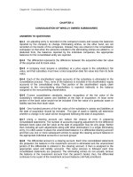
•14–101.
Determine the slope of end C of the overhang
beam. EI is constant.
w
C
A
Real Moment Function M. As indicated in Fig. a.
B
D
L
2
Virtual Moment Function mu. As indicated in Fig. b.
Virtual Work Equation.
L
1#u =
1 # uC =
uC =
mu M
dx
L0 EI
L
L>2
x1 w
w
1
(1) ¢
x 3 ≤ dx2 R
B
¢ - ≤ c A 11Lx1 - 12x1 2 B ddx1 +
EI L0
L 24
3L 2
L0
1
w
B
EI 24L L0
uC = -
L
A 12x1 3 - 11Lx1 2 B dx1 +
w
3L L0
L>2
x2 3 dx2 R
13wL3
13wL3
=
576EI
576EI
Ans.
1238
L
2
L
2
14 Solutions 46060_Part2
6/11/10
8:19 AM
Page 1239
© 2010 Pearson Education, Inc., Upper Saddle River, NJ. All rights reserved. This material is protected under all copyright laws as they currently
exist. No portion of this material may be reproduced, in any form or by any means, without permission in writing from the publisher.
14–102. Determine the displacement of point D of the
overhang beam. EI is constant.
w
L
2
Virtual Work Equation.
L
1 # ¢D =
L0
mM
dx
EI
1
B
EI L0
L>2
¢
x1 w
≤ c A 11Lx1 - 12x1 2 B ddx1
2 24
L>2
+
L0
¢D =
w
B
48EI L0
¢D =
wL4
T
96EI
L>2
¢
x2 w
≤ c A 13Lx2 - 12x2 2 - L2 B ddx2 R
2 24
A 11Lx1 2 - 12x1 3 B dx1 +
L>2
L0
B
D
Virtual Moment Function m. As indicated in Fig. b.
1#¢ =
C
A
Real Moment Function M. As indicated in Fig. a.
A 13Lx2 2 - 12x2 3 - L2x2 B dx2 R
Ans.
1239
L
2
L
2
14 Solutions 46060_Part2
6/11/10
8:19 AM
Page 1240
© 2010 Pearson Education, Inc., Upper Saddle River, NJ. All rights reserved. This material is protected under all copyright laws as they currently
exist. No portion of this material may be reproduced, in any form or by any means, without permission in writing from the publisher.
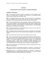
14–103. Determine the displacement of end C of the
overhang Douglas fir beam.
400 lb
a
Real Moment Functions M. As indicated in Fig. a.
400 lbиft
A
B
a
Virtual Moment Functions m. As indicated in Fig. b.
8 ft
Virtual Work Equation.
4 ft
3 in.
L
mM
1#¢ =
dx
L0 EI
1 lb # ¢ C =
¢C =
=
=
1
B
EI L0
1
B
EI L0
6 in.
8 ft
8 ft
4 ft
125x1 2dx1 +
Section a – a
4 ft
(0.5x1)(250x1)dx1 +
L0
L0
x2(400x2 + 400)dx2 R
A 400x2 2 + 400x2 B dx2 R
33066.67 lb # ft3
EI
33066.67 A 12 3 B
1.90 A 106 B c
1
(3) A 63 B d
12
= 0.5569 in. = 0.557 in. T
Ans.
1240
C
14 Solutions 46060_Part2
6/11/10
8:19 AM
Page 1241
© 2010 Pearson Education, Inc., Upper Saddle River, NJ. All rights reserved. This material is protected under all copyright laws as they currently
exist. No portion of this material may be reproduced, in any form or by any means, without permission in writing from the publisher.
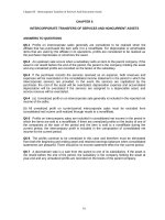
*14–104. Determine the slope at A of the overhang white
spruce beam.
400 lb
a
400 lbиft
A
8 ft
Virtual Moment Functions m. indicated in Fig. b.
6 in.
L
muM
1#u =
dx
L0 EI
uA =
=
=
1
B
EI L0
1
B
EI L0
8 ft
Section a – a
8 ft
4 ft
(1 - 0.125x1)(250x1)dx1 +
L0
0(400x2 + 400)dx2 R
A 250x1 - 31.25x1 2 B dx1 + 0 R
2666.67 lb # ft2
EI
2666.67 A 12 2 B
1.940 A 106 B c
1
(3) A 63 B d
12
= 0.00508 rad = 0.00508 rad
Ans.
1241
C
4 ft
3 in.
Virtual Work Equation.
1 lb # ft # uA =
B
a
Real Moment Functions M. As indicated in Fig. a.
14 Solutions 46060_Part2
6/11/10
8:19 AM
Page 1242
© 2010 Pearson Education, Inc., Upper Saddle River, NJ. All rights reserved. This material is protected under all copyright laws as they currently
exist. No portion of this material may be reproduced, in any form or by any means, without permission in writing from the publisher.
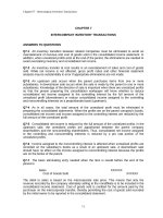
•14–105. Determine the displacement at point B. The
moment of inertia of the center portion DG of the shaft is
2I, whereas the end segments AD and GC have a moment
of inertia I. The modulus of elasticity for the material is E.
w
A
C
D
a
Real Moment Function M(x): As shown on Fig. a.
Virtual Moment Functions m(x): As shown on Fig. b.
Virtual Work Equation: For the slope at point B, apply Eq. 14–42.
L
1#¢ =
mM
dx
L0 EI
1 # ¢B = 2 B
a
x1
1
a b(w ax1)dx1 R
EI L0
2
a
+ 2B
¢B =
1
1
w 2
(x + a) B wa(a + x2) x R dx2 R
2EI L0 2 2
2 2
65wa4
48EI
Ans.
T
1242
B
a
G
a
a
14 Solutions 46060_Part2
6/11/10
8:19 AM
Page 1243
© 2010 Pearson Education, Inc., Upper Saddle River, NJ. All rights reserved. This material is protected under all copyright laws as they currently
exist. No portion of this material may be reproduced, in any form or by any means, without permission in writing from the publisher.
14–106. Determine the displacement of the shaft at C. EI
is constant.
w0
A
B
C
L
–
2
L
–
2
L
1 # ¢C =
mM
dx
L0 E I
L
¢C
2
w0 L
w0 3
1
1
= 2a
b
a x1 b a
x1 x bdx1
E I L0
2
4
3L 1
=
w0 L4
120 E I
Ans.
14–107. Determine the slope of the shaft at the bearing
support A. EI is constant.
w0
A
B
C
L
–
2
L
1 # uA =
mu M
dx
L0 E I
L
uA
2
w0 L
w0 3
1
1
=
C
a1 x ba
x1 x bdx1 S
E I L0
L 1
4
3L 1
L
2
+
=
L0
a
w0L
w0 3
1
x ba
x x bdx2
L 2
4 2
3L 2
5 w0L3
192 E I
Ans.
1243
L
–
2
14 Solutions 46060_Part2
6/11/10
8:19 AM
Page 1244
© 2010 Pearson Education, Inc., Upper Saddle River, NJ. All rights reserved. This material is protected under all copyright laws as they currently
exist. No portion of this material may be reproduced, in any form or by any means, without permission in writing from the publisher.
*14–108. Determine the slope and displacement of end C
of the cantilevered beam. The beam is made of a material
having a modulus of elasticity of E. The moments of
inertia for segments AB and BC of the beam are 2I and I,
respectively.
P
L
2
Real Moment Function M. As indicated in Fig. a.
Virtual Moment Functions mu and M. As indicated in Figs. b and c.
Virtual Work Equation. For the slope at C,
L
1#u =
L0
1 # uC =
uC =
mu M
dx
EI
1
EI L0
L>2
1(Px1)dx1 +
1
2 EI L0
L>2
1 B Pa x2 +
L
b R dx2
2
5PL2
16 EI
Ans.
For the displacement at C,
L
1#¢ =
1 # ¢C =
¢C =
mM
dx
L0 EI
1
EI L0
L>2
x1(Px1)dx1 +
1
2EI L0
L>2
¢ x2 +
L
L
≤ B P ¢ x2 + ≤ R dx2
2
2
3PL
T
16EI
Ans.
1244
C
B
A
L
2
14 Solutions 46060_Part2
6/11/10
8:19 AM
Page 1245
© 2010 Pearson Education, Inc., Upper Saddle River, NJ. All rights reserved. This material is protected under all copyright laws as they currently
exist. No portion of this material may be reproduced, in any form or by any means, without permission in writing from the publisher.
•14–109.
Determine the slope at A of the A-36 steel
W200 * 46 simply supported beam.
12 kN/m
6 kN/m
Real Moment Function M. As indicated in Fig. a.
A
3m
Virtual Work Equation.
L
1#u =
mu M
dx
EI
L0
1kN # m # uA =
1
B
EI L0
3m
(1 - 0.1667x1) A 31.5x1 - 6x1 2 B dx1
3m
+
uA =
=
=
1
B
EI L0
3m
L0
(0.1667x2) A 22.5x2 - 3x2 2 B dx2 R
A x1 3 - 11.25x1 2 + 31.5x1 B dx1 +
3m
L0
B
C
Virtual Moment Functions m. As indicated in Fig. b.
A 3.75x2 2 - 0.5x2 3 B dx2 R
84.375 kN # m2
EI
84.375 A 103 B
200 A 109 B c45.5 A 10 - 6 B d
= 0.009272 rad = 0.00927 rad
Ans.
1245
3m
14 Solutions 46060_Part2
6/11/10
8:19 AM
Page 1246
© 2010 Pearson Education, Inc., Upper Saddle River, NJ. All rights reserved. This material is protected under all copyright laws as they currently
exist. No portion of this material may be reproduced, in any form or by any means, without permission in writing from the publisher.
14–110. Determine the displacement at point C of the
A-36 steel W200 * 46 simply supported beam.
12 kN/m
6 kN/m
Real Moment Functions M. As indicated in Fig. a.
A
3m
Virtual Work Equation.
L
1#¢ =
mM
dx
L0 EI
1kN # ¢ C =
1
B
EI L0
(0.5x1) A 31.5x1 - 6x1 2 B dx1
3m
3m
+
¢C =
=
=
1
B
EI L0
3m
L0
(0.5x2) A 22.5x2 - 3x2 2 B dx2 R
A 15.75x1 2 - 3x1 3 B dx1 +
3m
L0
B
C
Virtual Moment Functions m. As indicated in Figs. b.
A 11.25x2 2 - 1.5x2 3 B dx2 R
151.875 kN # m3
EI
151.875 A 103 B
200 A 109 B c45.5 A 10 - 6 B d
= 0.01669 m = 16.7 mm T
Ans.
1246
3m
14 Solutions 46060_Part2
6/11/10
8:19 AM
Page 1247
© 2010 Pearson Education, Inc., Upper Saddle River, NJ. All rights reserved. This material is protected under all copyright laws as they currently
exist. No portion of this material may be reproduced, in any form or by any means, without permission in writing from the publisher.
14–111. The simply supported beam having a square cross
section is subjected to a uniform load w. Determine the
maximum deflection of the beam caused only by bending,
and caused by bending and shear. Take E = 3G.
w
a
L
For bending and shear,
L
1#¢ =
L
fsvV
mM
dx +
dx
EI
L0 GA
L0
L>2
¢ = 2
L0
x
A 12 x B A wL
2 x - w 2 B dx
2
EI
L>2
+ 2
L0
A 65 B A 12 B A wL
2 - wx B dx
GA
A B wL
wx2 2 L>2
wx4 2 L>2
1 wL 3
a
x b
+
a
x b
EI
6
8
GA
2
2
0
0
6
5
=
=
5wL4
3wL2
+
384EI
20 GA
5wL4
¢ =
=
1
384(3G) A 12
B a4
+
3wL2
20(G)a2
20wL4
3wL2
+
4
384Ga
20Ga2
= a
L 2
L 2
w
5
3
ba b Ba ba b +
R
a
a
G
96
20
Ans.
For bending only,
¢ =
5w L 4
a b
96G a
Ans.
1247
a
14 Solutions 46060_Part2
6/11/10
8:19 AM
Page 1248
© 2010 Pearson Education, Inc., Upper Saddle River, NJ. All rights reserved. This material is protected under all copyright laws as they currently
exist. No portion of this material may be reproduced, in any form or by any means, without permission in writing from the publisher.
*14–112. The frame is made from two segments, each
of length L and flexural stiffness EI. If it is subjected
to the uniform distributed load determine the vertical
displacement of point C. Consider only the effect of bending.
w
B
C
L
L
A
Real Moment Function M(x): As shown on Fig. a.
Virtual Moment Functions m(x): As shown on Fig. b.
Virtual Work Equation: For the vertical displacement at point C,
L
1#¢ =
L0
mM
dx
EI
L
1 # (¢ C)v =
(¢ C)v =
L
1
w 2
1
wL2
(1.00x1)a x1 b dx1 +
(1.00L)a
b dx2
EI L0
2
EI L0
2
5wL4
8EI
Ans.
T
1248
14 Solutions 46060_Part2
6/11/10
8:19 AM
Page 1249
© 2010 Pearson Education, Inc., Upper Saddle River, NJ. All rights reserved. This material is protected under all copyright laws as they currently
exist. No portion of this material may be reproduced, in any form or by any means, without permission in writing from the publisher.
•14–113.
The frame is made from two segments, each
of length L and flexural stiffness EI. If it is subjected to
the uniform distributed load, determine the horizontal
displacement of point B. Consider only the effect of bending.
w
B
C
L
Real Moment Function M(x): As shown on Fig. a.
L
Virtual Moment Functions m(x): As shown on Fig. b.
Virtual Work Equation: For the horizontal displacement at point B,
A
L
1#¢
mM
=
dx
L0 EI
L
1 # (¢ B)h =
(¢ B)h =
L
1
w 2
1
wL2
(0)a x1 b dx1 +
(1.00L - 1.00x2)a
b dx2
EI L0
2
EI L0
2
wL4
:
4EI
Ans.
14–114. Determine the vertical displacement of point A
on the angle bracket due to the concentrated force P. The
bracket is fixed connected to its support. EI is constant.
Consider only the effect of bending.
P
L
A
L
1 # ¢ Av =
mM
dx
L0 EI
L
L
¢ Av =
=
L
1
C
(x1)(Px1)dx1 +
(1L)(PL)dx2 S
EI L0
L0
4PL3
3EI
Ans.
1249
14 Solutions 46060_Part2
6/11/10
8:19 AM
Page 1250
© 2010 Pearson Education, Inc., Upper Saddle River, NJ. All rights reserved. This material is protected under all copyright laws as they currently
exist. No portion of this material may be reproduced, in any form or by any means, without permission in writing from the publisher.
14–115. Beam AB has a square cross section of 100 mm by
100 mm. Bar CD has a diameter of 10 mm. If both members
are made of A-36 steel, determine the vertical displacement
of point B due to the loading of 10 kN.
C
10 kN
2m
D
A
3m
Real Moment Function M(x): As shown on Fig. a.
Virtual Moment Functions m(x): As shown on Fig. b.
Virtual Work Equation: For the displacement at point B,
L
1#¢ =
1 kN # ¢ B =
L0
nNL
mM
dx +
EI
AE
1
EI L0
+
3m
(0.6667x1)(6.667x1)dx1
1
EI L0
+
¢B =
2m
(1.00x2)(10.0x2)dx2
1.667(16.667)(2)
AE
66.667 kN # m3
55.556 kN # m
+
EI
AE
66.667(1000)
=
200(10 ) C
9
1
12
(0.1) A 0.1
3
BD
= 0.04354 m = 43.5 mm
55.556(1000)
+
C A 0.012 B D C 200 A 109 B D
p
4
Ans.
T
1250
B
2m
14 Solutions 46060_Part2
6/11/10
8:19 AM
Page 1251
© 2010 Pearson Education, Inc., Upper Saddle River, NJ. All rights reserved. This material is protected under all copyright laws as they currently
exist. No portion of this material may be reproduced, in any form or by any means, without permission in writing from the publisher.
*14–116. Beam AB has a square cross section of 100 mm
by 100 mm. Bar CD has a diameter of 10 mm. If both
members are made of A-36 steel, determine the slope at A
due to the loading of 10 kN.
C
10 kN
2m
Real Moment Function M(x): As shown on Fig. a.
D
A
Virtual Moment Functions mu(x): As shown on Fig. b.
B
3m
2m
Virtual Work Equation: For the slope at point A,
L
1#u =
1 kN # m # uA =
muM
nNL
dx +
EI
AE
L0
3m
1
EI L0
(1 - 0.3333x1)(6.667x1)dx1
+
uA =
1
EI L0
2m
0(10.0x2)dx2 +
10.0 kN # m2
11.111 kN
EI
AE
11.111(1000)
10.0(1000)
=
(-0.3333)(16.667)(2)
AE
200 A 10
9
B C (0.1) A 0.1 B D
1
12
3
-
C A 0.012 B D C 200 A 109 B D
p
4
= 0.00529 rad
Ans.
14–117. Bar ABC has a rectangular cross section of
300 mm by 100 mm. Attached rod DB has a diameter
of 20 mm. If both members are made of A-36 steel,
determine the vertical displacement of point C due to the
loading. Consider only the effect of bending in ABC and
axial force in DB.
D
4m
20 kN
300 mm
100 mm
A
Real Moment Function M(x): As shown on Fig. a.
3m
Virtual Moment Functions m(x): As shown on Fig. b.
Virtual Work Equation: For the displacement at point C,
L
1#¢ =
L0
mM
nNL
dx +
EI
AE
1 kN # ¢ C = 2c
¢C =
1
EI L0
3m
(1.00x)(20.0x) dx d +
2.50(50.0) (5)
AE
360 kN # m3
625 kN # m
+
EI
AE
625(1000)
360(1000)
=
200 A 10
9
B C (0.1) A 0.3 B D
1
12
+
3
B
C A 0.02 2 B D C 200 A 109 B D
p
4
= 0.017947 m = 17.9 mm T
Ans.
1251
3m
C
14 Solutions 46060_Part2
6/11/10
8:19 AM
Page 1252
© 2010 Pearson Education, Inc., Upper Saddle River, NJ. All rights reserved. This material is protected under all copyright laws as they currently
exist. No portion of this material may be reproduced, in any form or by any means, without permission in writing from the publisher.
14–118. Bar ABC has a rectangular cross section of
300 mm by 100 mm. Attached rod DB has a diameter
of 20 mm. If both members are made of A-36 steel,
determine the slope at A due to the loading. Consider only
the effect of bending in ABC and axial force in DB.
D
4m
20 kN
300 mm
100 mm
A
B
3m
Real Moment Function M(x): As shown on Fig. a.
Virtual Moment Functions mu (x): As shown on Fig. b.
Virtual Work Equation: For the slope at point A,
L
1#u =
muM
nNL
dx +
AE
L0 EI
1 kN # m # uA =
uA =
1
EI L0
3m
(1 - 0.3333x)(20.0x)dx +
30.0 kN # m2
104.167 kN
EI
AE
104.167(1000)
30.0(1000)
=
( -0.41667)(50.0)(5)
AE
200 A 10
9
B C (0.1) A 0.3 B D
1
12
3
-
C A 0.02 2 B D C 200 A 109 B D
p
4
= -0.991 A 10 - 3 B rad = 0.991 A 10 - 3 B rad
Ans.
1252
3m
C
14 Solutions 46060_Part2
6/11/10
8:19 AM
Page 1253
© 2010 Pearson Education, Inc., Upper Saddle River, NJ. All rights reserved. This material is protected under all copyright laws as they currently
exist. No portion of this material may be reproduced, in any form or by any means, without permission in writing from the publisher.
14–119. Determine the vertical displacement of point C.
The frame is made using A-36 steel W250 * 45 members.
Consider only the effects of bending.
15 kN/m
15 kN
D
B
C
2.5 m
5m
A
Real Moment Functions M. As indicated in Fig. a.
Virtual Moment Functions m. As indicated in Fig. b.
Virtual Work Equation.
L
1#¢ =
L0
mM
dx
EI
1 kN # (¢ C)v =
1
B
EI L0
(0.5x1) A 52.5x1 - 7.5x1 2 B dx1
2.5 m
5m
+
0(15x2)dx2
L0
2.5 m
+
(¢ C)v =
1
B
EI L0
2.5 m
L0
A 26.25x1 2 - 3.75x1 3 B dx1 + 0
2.5 m
+
=
=
(0.5x3) A 75 + 22.5x3 - 7.5x3 2 B dx2 R
L0
A 37.5x3 + 11.25x3 2 - 3.75x3 3 B dx3 R
239.26 kN # m3
EI
239.26 A 103 B
200 A 109 B c71.1 A 10 - 6 B d
= 0.01683 m = 16.8 mm T
Ans.
1253
2.5 m
14 Solutions 46060_Part2
6/11/10
8:19 AM
Page 1254
© 2010 Pearson Education, Inc., Upper Saddle River, NJ. All rights reserved. This material is protected under all copyright laws as they currently
exist. No portion of this material may be reproduced, in any form or by any means, without permission in writing from the publisher.
*14–120. Determine the horizontal displacement of end
B. The frame is made using A-36 steel W250 * 45
members. Consider only the effects of bending.
15 kN/m
15 kN
D
B
C
2.5 m
5m
Real Moment Functions M. As indicated in Fig. a.
A
Virtual Moment Functions m. As indicated in Fig. b.
Virtual Work Equation.
L
1#¢ =
L0
mM
dx
EI
1 kN # (¢ B)h =
(¢ B)h =
=
=
1
B
EI L0
1
B
EI L0
5m
x1 A 52.5x1 - 7.5x1 2 B dx1 +
5m
A 52.5x1 2 - 7.5x1 3 B dx1 +
5m
L0
x2(15x2)dx2 R
5m
L0
15x2 2dx2 R
1640.625 kN # m3
EI
1640.625 A 103 B
200 A 109 B c71.1 A 10 - 6 B d
= 0.1154 m = 115 mm :
Ans.
1254
2.5 m
14 Solutions 46060_Part2
6/11/10
8:19 AM
Page 1255
© 2010 Pearson Education, Inc., Upper Saddle River, NJ. All rights reserved. This material is protected under all copyright laws as they currently
exist. No portion of this material may be reproduced, in any form or by any means, without permission in writing from the publisher.
•14–121. Determine the displacement at point C. EI is
constant.
A
B
a
C
M0
C
M0
a
L
mM
dx
L0 E I
1 # ¢C =
a
¢C =
L0
(1x) A
EI
5 M0 a
6EI
=
14–122.
M0
a
xB
a
dx +
(1x) M0
dx
EI
L0
2
Ans.
Determine the slope at B. EI is constant.
A
B
a
L
mu M
dx
L0 E I
1 # uB =
a
uB =
=
L0
A xa B A Ma0 x B
EI
dx
M0 a
3EI
14–123.
Ans.
Solve Prob. 14–72 using Castigliano’s theorem.
Member
N
0N>0P
N(P = 0)
L
N(0N>0P)L
AB
1.1547P + 800
1.1547
800
120
110851.25
BC
–0.5774P
–0.5774
0
60
0
© = 110851.25
¢ Bb = ©N a
0N L
110851.25
110851.25
= 0.00191 in.
b
=
=
0P AE
AE
(2)(29)(106)
1255
Ans.
a
14 Solutions 46060_Part2
6/11/10
8:19 AM
Page 1256
© 2010 Pearson Education, Inc., Upper Saddle River, NJ. All rights reserved. This material is protected under all copyright laws as they currently
exist. No portion of this material may be reproduced, in any form or by any means, without permission in writing from the publisher.
*14–124.
Solve Prob. 14–73 using Castigliano’s theorem.
Member Force N: Member forces due to external force P and external applied
forces are shown on the figure.
Castigliano’s Second Theorem:
N(P = 200 lb)
L
–0.8333P
0N
0P
–0.8333
–166.67
10.0
0N
bL
0P
1388.89
BC
0.8333P
0.8333
166.67
10.0
1388.89
AC
0.500P
0.500
100.00
12
600.00
Member
N
AB
Na
© 3377.78 lb # ft
0N L
b
¢ = a Na
0P AE
(¢ B)h =
3377.78 lb # ft
AE
3377.78(12)
=
•14–125.
2 C 29.0 A 106 B D
= 0.699 A 10 - 3 B in. :
Ans.
Solve Prob. 14–75 using Castigliano’s theorem.
Member
N
N(P = 30)
0N>0P
L
N(0N>0P)L
AB
1.50P
1.50
45.00
3.0
202.50
AD
5 213
0
5213
213
0
BD
–20
0
–20
2.0
0
BC
1.5P
1.5
45.00
3.0
202.50
CD
–0.5 213P
–0.5 213
-15 213
213
351.54
–0.5 213
-20 213
213
468.72
DE
– A 0.5 213P + 5 213 B
1225.26 A 10 B
0N L
b
=
0P AE
300 A 10 - 6 B (200) A 109 B
© = 1225.26
3
¢ Cv = ©Na
= 0.02.04 m = 20.4 mm
Ans.
1256
14 Solutions 46060_Part2
6/11/10
8:19 AM
Page 1257
© 2010 Pearson Education, Inc., Upper Saddle River, NJ. All rights reserved. This material is protected under all copyright laws as they currently
exist. No portion of this material may be reproduced, in any form or by any means, without permission in writing from the publisher.
14–126. Solve Prob. 14–76 using Castigliano’s theorem.
Member
N
N(P = 0)
0N>0P
N(0N>0P)L
L
AB
45
0
45.00
3
0
AD
0.25 213P + 5 213
0.25213
5213
213
58.59
BC
45
0
45
3
0
BD
–20
0
–20
2
0
CD
–15 213
0
-15 213
213
0
–0.25213
-20 213
213
234.36
– A 0.25 213P + 20 213 B
DE
¢ Dv = ©Na
© = 292.95
292.95 A 103 B
292.95
0N L
b
=
=
0P AE
AE
300 A 10 - 6 B (200) A 109 B
= 4.88 A 10 - 3 B m = 4.88 mm
14–127.
Ans.
Solve Prob. 14–77 using Castigliano’s theorem.
Member Forces N: Member forces due to external force P and external applied
forces are shown on the figure.
Castigliano’s Second Theorem:
3.333
96
0N
bL
0P
213.33
0.6667
3.333
96
213.33
0
0
0
72
0
DE
0
0
0
96
0
EF
0
0
0
96
0
AF
0
0
0
72
0
AE
– 0.8333P
– 0.8333
–4.167
120
416.67
CE
– 0.8333P
– 0.8333
–4.167
120
416.67
BE
1.00P
1.00
5.00
72
360.00
Member
N
AB
0.6667P
0N
0P
0.6667
BC
0.6667P
CD
N(P = 5 kip)
L
Na
©1620 kip # in
0N L
b
¢ = a Na
0P AE
(¢ B)v =
1620 kip # in.
AE
1620
=
4.5 C 29.0 A 103 B D
= 0.0124 in. T
Ans.
1257
14 Solutions 46060_Part2
6/11/10
8:19 AM
Page 1258
© 2010 Pearson Education, Inc., Upper Saddle River, NJ. All rights reserved. This material is protected under all copyright laws as they currently
exist. No portion of this material may be reproduced, in any form or by any means, without permission in writing from the publisher.
*14–128.
Solve Prob. 14–78 using Castigliano’s theorem.
Member Forces N: Member forces due to external force P and external applied forces
are shown on the figure.
Castigliano’s Second Theorem:
N(P = 0)
L
3.333
96
0N
bL
0P
213.33
AB
0.6667P+3.333
0N
0P
0.6667
BC
0.6667P+3.333
0.6667
3.333
96
213.33
CD
0
0
0
72
0
DE
0
0
0
96
0
EF
0
0
0
96
0
AF
0
0
0
72
0
AE
–(0.8333P + 4.167)
– 0.8333
–4.167
120
416.67
CE
–(0.8333P + 4.167)
– 0.8333
–4.167
120
416.67
BE
5.0
0
5.00
72
0
Member
N
Na
©1260 kip # in
0N L
b
¢ = a Na
0P AE
(¢ E)v =
1260 kip # in.
AE
1260
=
•14–129.
4.5 C 29.0 A 103 B D
= 0.00966 in. T
Ans.
Solve Prob. 14–79 using Castigliano’s theorem.
Member
N
0N>0P
N(P = 4)
L
N(0N>0P)L
AB
0
0
0
1.5
0
AC
–1.25P
–1.25
–5
2.5
15.625
AD
P
1
4
2.0
8.00
BC
P
1
4
2.0
8.00
CD
–(5 -0.75P)
0.75
–2
1.5
–2.25
© = 29.375
¢ Bh = ©Na
29.375 A 103 B
0N
L
ba
b =
= 0.367 A 10 - 3 B m
0P
AE
400 A 10 - 6 B (200) A 109 B
= 0.367 mm
Ans.
1258
14 Solutions 46060_Part2
6/11/10
8:19 AM
Page 1259
© 2010 Pearson Education, Inc., Upper Saddle River, NJ. All rights reserved. This material is protected under all copyright laws as they currently
exist. No portion of this material may be reproduced, in any form or by any means, without permission in writing from the publisher.
14–130.
Solve Prob. 14–80 using Castigliano’s theorem.
Member
N
0N>0P
N(P = 5)
L
N(0N>0P)L
AB
0
0
0
1.5
0
AC
–5
0
–5
2.5
0
AD
4
0
4
2.0
0
BC
4
0
4
2.0
0
CD
–(P - 3)
–1
–2
1.5
3
© = 3
3 A 10 B
3
0N L
b
=
=
0P AE
AE
400 A 10 6 B (200) A 109 B
3
¢ Cv = ©Na
= 37.5 A 10 - 6 B m = 0.0375 mm
14–131.
Ans.
Solve Prob. 14–81 using Castigliano’s theorem.
Member Forces N: Member forces due to external force P and external applied
forces are shown on the figure.
Castigliano’s Second Theorem:
N(P = 30 kN)
L
–22.5
1.5
0N
bL
0P
25.3125
AB
– 0.750P
0N
0P
– 0.750
BC
– 0.750P
– 0.750
–22.5
1.5
25.3125
AE
1.25P
1.25
37.5
2.5
117.1875
CE
–(1.25P + 25.0)
– 1.25
–62.5
2.5
195.3125
BE
20.0
0
20.0
2
0
DE
1.50P+15.0
1.50
60.0
1.5
135.00
Member
N
Na
#
a 498.125 kN m
0N L
b
¢ = a Na
0P AE
(¢ A)v =
=
498.125 kN # m
AE
498.125 A 103 B
0.400 A 10 - 3 B C 200 A 109 B D
= 6.227 A 10 - 3 B m = 6.23 mm T
Ans.
1259
14 Solutions 46060_Part2
6/11/10
8:19 AM
Page 1260
© 2010 Pearson Education, Inc., Upper Saddle River, NJ. All rights reserved. This material is protected under all copyright laws as they currently
exist. No portion of this material may be reproduced, in any form or by any means, without permission in writing from the publisher.
*14–132.
Solve Prob. 14–82 using Castigliano’s theorem.
Member Forces N: Member forces due to external force P and external applied
forces are shown on the figure.
Castigliano’s Second Theorem:
0N
bL
0P
0
AB
– 22.5
0N
0P
0
BC
– 22.5
0
–22.5
1.5
0
AE
37.5
0
37.5
2.5
0
CE
–(1.25P + 37.5)
– 1.25
–62.5
2.5
195.3125
BE
1.00P
1.00
20.0
2
40.0
DE
0.750P + 45
0.750
60.0
1.5
67.50
Member
N
N(P = 20 kN)
L
–22.5
1.5
Na
#
a 302.8125 kN m
0N L
b
¢ = a Na
0P AE
(¢ B)v =
=
302.8125 kN # m
AE
302.8125 A 103 B
0.400 A 10 - 3 B C 200 A 109 B D
= 3.785 A 10 - 3 B m = 3.79 mm T
•14–133.
Ans.
Solve Prob. 14–83 using Castigliano’s theorem.
¢ Cv = ©N a
21232
21232
0N L
= 0.163 in.
b
=
=
0P AE
AE
4.5 (29)(103)
Ans.
1260
14 Solutions 46060_Part2
6/11/10
8:19 AM
Page 1261
© 2010 Pearson Education, Inc., Upper Saddle River, NJ. All rights reserved. This material is protected under all copyright laws as they currently
exist. No portion of this material may be reproduced, in any form or by any means, without permission in writing from the publisher.
14–134.
Solve Prob. 14–84 using Castigliano’s theorem.
¢ Hv = ©N a
20368
20368
0N L
b
=
=
0P AE
AE
4.5 (29) A 103 B
= 0.156 in.
14–135.
Ans.
Solve Prob. 14–87 using Castigliano’s theorem.
0M1
x1
=
0P¿
2
0M2
x2
a
=
+
0P¿
2
2
Set P¿ = 0
M1 = Px1
M2 = Pa
a
¢C =
L0
Ma
0M dx
b
0P EI
a
= (2)
=
1
1
(Px1) a x1 b dx +
B
EI L0
2
L0
a>2
(Pa) a
1
a
+ x2 bdx2 R
2
2
23Pa3
24 EI
Ans.
1261
14 Solutions 46060_Part2
6/11/10
8:19 AM
Page 1262
© 2010 Pearson Education, Inc., Upper Saddle River, NJ. All rights reserved. This material is protected under all copyright laws as they currently
exist. No portion of this material may be reproduced, in any form or by any means, without permission in writing from the publisher.
*14–136.
Solve Prob. 14–88 using Castigliano’s theorem.
0M1
= x1
0P
0M2
= -0.5 x2
0P
Set P = 15 kN
M2 = -1.5x2 - 2x22
M1 = 15x1
L
¢A =
Ma
L0
0M dx
b
0P EI
1.5
3
A -1.5x2 - 2x22 B (-0.5x2)dx2 R
=
1
B
EI L0
=
43.875(103)
43.875 kN # m3
=
= 0.0579 m
1
9
EI
13(10 ) 12
(0.12)(0.18)3
(15x1)(x1)dx +
L0
= 57.9 mm
•14–137.
Ans.
Solve Prob. 14–90 using Castigliano’s theorem.
Internal Moment Function M(x): The internal moment function in terms of the
couple moment M¿ and the applied load are shown on the figure.
Castigliano’s Second Theorem: The slope at A can be determined with
0M(x1)
0M(x2)
= 1 - 0.100x1,
= 0 and setting M¿ = 0.
0M¿
0M¿
L
u =
uA =
=
=
L0
Ma
1
EI L0
0M dx
b
0M¿ EI
10 m
(2.50x1)(1 - 0.100x1)dx1 +
1
EI L0
5m
A 1.00x22 B (0)dx2
41.667 kN # m2
EI
41.667 A 103 B
200 A 109 B C 70 A 10 - 6 B D
Ans.
= 0.00298 rad
1262