Solution manual fundamentals of electric circuits 3rd edition chapter03
Bạn đang xem bản rút gọn của tài liệu. Xem và tải ngay bản đầy đủ của tài liệu tại đây (1.27 MB, 125 trang )
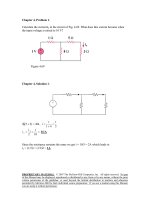
Chapter 3, Problem 1.
Determine Ix in the circuit shown in Fig. 3.50 using nodal analysis.
1 kΩ
4 kΩ
Ix
9V
+
_
2 kΩ
+
_
6V
Figure 3.50 For Prob. 3.1.
Chapter 3, Solution 1
Let Vx be the voltage at the node between 1-kΩ and 4-kΩ resistors.
9 − Vx 6 − Vx Vk
+
=
1k
4k
2k
Vx
Ix =
= 3 mA
2k
⎯⎯
→ Vx = 6
PROPRIETARY MATERIAL. © 2007 The McGraw-Hill Companies, Inc. All rights reserved. No part
of this Manual may be displayed, reproduced or distributed in any form or by any means, without the prior
written permission of the publisher, or used beyond the limited distribution to teachers and educators
permitted by McGraw-Hill for their individual course preparation. If you are a student using this Manual,
you are using it without permission.
Chapter 3, Problem 2.
For the circuit in Fig. 3.51, obtain v1 and v2.
Figure 3.51
Chapter 3, Solution 2
At node 1,
− v1 v1
v − v2
−
= 6+ 1
10
5
2
60 = - 8v1 + 5v2
(1)
At node 2,
v2
v − v2
= 3+ 6+ 1
4
2
36 = - 2v1 + 3v2
(2)
Solving (1) and (2),
v1 = 0 V, v2 = 12 V
PROPRIETARY MATERIAL. © 2007 The McGraw-Hill Companies, Inc. All rights reserved. No part
of this Manual may be displayed, reproduced or distributed in any form or by any means, without the prior
written permission of the publisher, or used beyond the limited distribution to teachers and educators
permitted by McGraw-Hill for their individual course preparation. If you are a student using this Manual,
you are using it without permission.
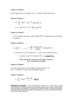
Chapter 3, Problem 3.
Find the currents i1 through i4 and the voltage vo in the circuit in Fig. 3.52.
Figure 3.52
Chapter 3, Solution 3
Applying KCL to the upper node,
10 =
v0 vo vo
v
+
+
+2+ 0
10 20 30
60
i1 =
v0
v
v
v
= 4 A , i2 = 0 = 2 A, i3 = 0 = 1.3333 A, i4 = 0 = 666.7 mA
10
20
30
60
v0 = 40 V
PROPRIETARY MATERIAL. © 2007 The McGraw-Hill Companies, Inc. All rights reserved. No part
of this Manual may be displayed, reproduced or distributed in any form or by any means, without the prior
written permission of the publisher, or used beyond the limited distribution to teachers and educators
permitted by McGraw-Hill for their individual course preparation. If you are a student using this Manual,
you are using it without permission.
Chapter 3, Problem 4.
Given the circuit in Fig. 3.53, calculate the currents i1 through i4.
Figure 3.53
Chapter 3, Solution 4
2A
v1
i1
4A
5Ω
i2
v2
i3
10 Ω
10 Ω
i4
5Ω
5A
At node 1,
4 + 2 = v1/(5) + v1/(10)
v1 = 20
At node 2,
5 - 2 = v2/(10) + v2/(5)
v2 = 10
i1 = v1/(5) = 4 A, i2 = v1/(10) = 2 A, i3 = v2/(10) = 1 A, i4 = v2/(5) = 2 A
PROPRIETARY MATERIAL. © 2007 The McGraw-Hill Companies, Inc. All rights reserved. No part
of this Manual may be displayed, reproduced or distributed in any form or by any means, without the prior
written permission of the publisher, or used beyond the limited distribution to teachers and educators
permitted by McGraw-Hill for their individual course preparation. If you are a student using this Manual,
you are using it without permission.
Chapter 3, Problem 5.
Obtain v0 in the circuit of Fig. 3.54.
Figure 3.54
Chapter 3, Solution 5
Apply KCL to the top node.
30 − v 0 20 − v 0 v 0
+
=
2k
5k
4k
v0 = 20 V
Chapter 3, Problem 6.
Use nodal analysis to obtain v0 in the circuit in Fig. 3.55.
Figure 3.55
Chapter 3, Solution 6
i1 + i2 + i3 = 0
v 2 − 12 v 0 v 0 − 10
+
+
=0
4
6
2
or v0 = 8.727 V
PROPRIETARY MATERIAL. © 2007 The McGraw-Hill Companies, Inc. All rights reserved. No part
of this Manual may be displayed, reproduced or distributed in any form or by any means, without the prior
written permission of the publisher, or used beyond the limited distribution to teachers and educators
permitted by McGraw-Hill for their individual course preparation. If you are a student using this Manual,
you are using it without permission.
Chapter 3, Problem 7.
Apply nodal analysis to solve for Vx in the circuit in Fig. 3.56.
+
2A
10 Ω
Vx
20 Ω
_
0.2 Vx
Figure 3.56 For Prob. 3.7.
Chapter 3, Solution 7
V − 0 Vx − 0
−2+ x
+
+ 0.2Vx = 0
10
20
0.35Vx = 2 or Vx = 5.714 V.
Substituting into the original equation for a check we get,
0.5714 + 0.2857 + 1.1428 = 1.9999 checks!
PROPRIETARY MATERIAL. © 2007 The McGraw-Hill Companies, Inc. All rights reserved. No part
of this Manual may be displayed, reproduced or distributed in any form or by any means, without the prior
written permission of the publisher, or used beyond the limited distribution to teachers and educators
permitted by McGraw-Hill for their individual course preparation. If you are a student using this Manual,
you are using it without permission.
Chapter 3, Problem 8.
Using nodal analysis, find v0 in the circuit in Fig. 3.57.
Figure 3.57
Chapter 3, Solution 8
3Ω
i1
v1
i3
5Ω
i2
+
V0
3V
2Ω
+
–
+ 4V0
–
–
1Ω
v1 v1 − 3 v1 − 4 v 0
+
+
=0
5
1
5
2
8
v 0 = v1 so that v1 + 5v1 - 15 + v1 - v1 = 0
5
5
or v1 = 15x5/(27) = 2.778 V, therefore vo = 2v1/5 = 1.1111 V
i1 + i2 + i3 = 0
But
PROPRIETARY MATERIAL. © 2007 The McGraw-Hill Companies, Inc. All rights reserved. No part
of this Manual may be displayed, reproduced or distributed in any form or by any means, without the prior
written permission of the publisher, or used beyond the limited distribution to teachers and educators
permitted by McGraw-Hill for their individual course preparation. If you are a student using this Manual,
you are using it without permission.
Chapter 3, Problem 9.
Determine Ib in the circuit in Fig. 3.58 using nodal analysis.
60 Ib
Ib
250 Ω
+ –
24 V
+
_
50 Ω
150 Ω
Figure 3.58 For Prob. 3.9.
Chapter 3, Solution 9
Let V1 be the unknown node voltage to the right of the 250-Ω resistor. Let the ground
reference be placed at the bottom of the 50-Ω resistor. This leads to the following nodal
equation:
V1 − 24 V1 − 0 V1 − 60I b − 0
=0
+
+
250
50
150
simplifying we get
3V1 − 72 + 15V1 + 5V1 − 300I b = 0
But I b =
24 − V1
. Substituting this into the nodal equation leads to
250
24.2V1 − 100.8 = 0 or V1 = 4.165 V.
Thus,
Ib = (24 – 4.165)/250 = 79.34 mA.
PROPRIETARY MATERIAL. © 2007 The McGraw-Hill Companies, Inc. All rights reserved. No part
of this Manual may be displayed, reproduced or distributed in any form or by any means, without the prior
written permission of the publisher, or used beyond the limited distribution to teachers and educators
permitted by McGraw-Hill for their individual course preparation. If you are a student using this Manual,
you are using it without permission.
Chapter 3, Problem 10.
Find i0 in the circuit in Fig. 3.59.
Figure 3.59
Chapter 3, Solution 10
3Ω
i1
v1
6Ω
i3
+ v0 –
i2
12V
+
–
+
v1
8Ω
+
–
–
2v0
At the non-reference node,
12 − v1 v1 v1 − 2v 0
=
+
3
8
6
(1)
But
-12 + v0 + v1 = 0
v0 = 12 - v1
(2)
Substituting (2) into (1),
12 − v1 v1 3v1 − 24
=
+
3
8
6
v0 = 3.652 V
PROPRIETARY MATERIAL. © 2007 The McGraw-Hill Companies, Inc. All rights reserved. No part
of this Manual may be displayed, reproduced or distributed in any form or by any means, without the prior
written permission of the publisher, or used beyond the limited distribution to teachers and educators
permitted by McGraw-Hill for their individual course preparation. If you are a student using this Manual,
you are using it without permission.
Chapter 3, Problem 11.
Find Vo and the power dissipated in all the resistors in the circuit of Fig. 3.60.
1Ω
36 V
Vo
+
_
4Ω
2Ω
–
+
12 V
Figure 3.60 For Prob. 3.11.
Chapter 3, Solution 11
At the top node, KVL gives
Vo − 36 Vo − 0 Vo − (−12)
+
+
=0
1
2
4
1.75Vo = 33 or Vo = 18.857V
P1Ω = (36–18.857)2/1 = 293.9 W
P2Ω = (Vo)2/2 = (18.857)2/2 = 177.79 W
P4Ω = (18.857+12)2/4 = 238 W.
PROPRIETARY MATERIAL. © 2007 The McGraw-Hill Companies, Inc. All rights reserved. No part
of this Manual may be displayed, reproduced or distributed in any form or by any means, without the prior
written permission of the publisher, or used beyond the limited distribution to teachers and educators
permitted by McGraw-Hill for their individual course preparation. If you are a student using this Manual,
you are using it without permission.
Chapter 3, Problem 12.
Using nodal analysis, determine Vo in the circuit in Fig. 3.61.
10 Ω
1Ω
Ix
30 V
+
_
2Ω
5Ω
4 Ix
+
Vo
_
Figure 3.61 For Prob. 3.12.
PROPRIETARY MATERIAL. © 2007 The McGraw-Hill Companies, Inc. All rights reserved. No part
of this Manual may be displayed, reproduced or distributed in any form or by any means, without the prior
written permission of the publisher, or used beyond the limited distribution to teachers and educators
permitted by McGraw-Hill for their individual course preparation. If you are a student using this Manual,
you are using it without permission.
Chapter 3, Solution 12
There are two unknown nodes, as shown in the circuit below.
10 Ω
30 V
At node 1,
+
_
1Ω
V1
Vo
2Ω
V1 − 30 V1 − 0 V1 − Vo
=0
+
+
10
2
1
16V1 − 10Vo = 30
4 Ix
5Ω
(1)
At node o,
Vo − V1
V −0
=0
− 4I x + o
1
5
− 5V1 + 6Vo − 20I x = 0
But Ix = V1/2. Substituting this in (2) leads to
–15V1 + 6Vo = 0 or V1 = 0.4Vo
(2)
(3)
Substituting (3) into 1,
16(0.4Vo) – 10Vo = 30 or Vo = –8.333 V.
PROPRIETARY MATERIAL. © 2007 The McGraw-Hill Companies, Inc. All rights reserved. No part
of this Manual may be displayed, reproduced or distributed in any form or by any means, without the prior
written permission of the publisher, or used beyond the limited distribution to teachers and educators
permitted by McGraw-Hill for their individual course preparation. If you are a student using this Manual,
you are using it without permission.
Chapter 3, Problem 13.
Calculate v1 and v2 in the circuit of Fig. 3.62 using nodal analysis.
Figure 3.62
Chapter 3, Solution 13
At node number 2, [(v2 + 2) – 0]/10 + v2/4 = 3 or v2 = 8 volts
But, I = [(v2 + 2) – 0]/10 = (8 + 2)/10 = 1 amp and v1 = 8x1 = 8volts
PROPRIETARY MATERIAL. © 2007 The McGraw-Hill Companies, Inc. All rights reserved. No part
of this Manual may be displayed, reproduced or distributed in any form or by any means, without the prior
written permission of the publisher, or used beyond the limited distribution to teachers and educators
permitted by McGraw-Hill for their individual course preparation. If you are a student using this Manual,
you are using it without permission.
Chapter 3, Problem 14.
Using nodal analysis, find vo in the circuit of Fig. 3.63.
Figure 3.63
Chapter 3, Solution 14
5A
v0
v1
1Ω
8Ω
2Ω
4Ω
40 V
20 V
–
+
+
–
At node 1,
v1 − v 0
40 − v 0
+5=
2
1
At node 0,
v1 − v 0
v
v + 20
+5= 0 + 0
2
4
8
v1 + v0 = 70
4v1 - 7v0 = -20
(1)
(2)
Solving (1) and (2), v0 = 27.27 V
PROPRIETARY MATERIAL. © 2007 The McGraw-Hill Companies, Inc. All rights reserved. No part
of this Manual may be displayed, reproduced or distributed in any form or by any means, without the prior
written permission of the publisher, or used beyond the limited distribution to teachers and educators
permitted by McGraw-Hill for their individual course preparation. If you are a student using this Manual,
you are using it without permission.
Chapter 3, Problem 15.
Apply nodal analysis to find io and the power dissipated in each resistor in the circuit of
Fig. 3.64.
Figure 3.64
PROPRIETARY MATERIAL. © 2007 The McGraw-Hill Companies, Inc. All rights reserved. No part
of this Manual may be displayed, reproduced or distributed in any form or by any means, without the prior
written permission of the publisher, or used beyond the limited distribution to teachers and educators
permitted by McGraw-Hill for their individual course preparation. If you are a student using this Manual,
you are using it without permission.
Chapter 3, Solution 15
5A
8Ω
v0
v1
1Ω
2Ω
4Ω
40 V
20 V
–
+
+
–
Nodes 1 and 2 form a supernode so that v1 = v2 + 10
At the supernode, 2 + 6v1 + 5v2 = 3 (v3 - v2)
At node 3, 2 + 4 = 3 (v3 - v2)
(1)
2 + 6v1 + 8v2 = 3v3
v3 = v2 + 2
(2)
(3)
Substituting (1) and (3) into (2),
2 + 6v2 + 60 + 8v2 = 3v2 + 6
v1 = v2 + 10 =
v2 =
− 56
11
54
11
i0 = 6vi = 29.45 A
2
v12
⎛ 54 ⎞
P65 =
= v12 G = ⎜ ⎟ 6 = 144.6 W
R
⎝ 11 ⎠
2
⎛ − 56 ⎞
P55 = v G = ⎜
⎟ 5 = 129.6 W
⎝ 11 ⎠
2
2
P35 = (v L − v 3 ) G = (2) 2 3 = 12 W
2
PROPRIETARY MATERIAL. © 2007 The McGraw-Hill Companies, Inc. All rights reserved. No part
of this Manual may be displayed, reproduced or distributed in any form or by any means, without the prior
written permission of the publisher, or used beyond the limited distribution to teachers and educators
permitted by McGraw-Hill for their individual course preparation. If you are a student using this Manual,
you are using it without permission.
Chapter 3, Problem 16.
Determine voltages v1 through v3 in the circuit of Fig. 3.65 using nodal analysis.
Figure 3.65
Chapter 3, Solution 16
2S
v2
v1
i0
2A
+
1S
v0
4S
8S
v3
13 V
–
+
–
At the supernode,
2 = v1 + 2 (v1 - v3) + 8(v2 – v3) + 4v2, which leads to 2 = 3v1 + 12v2 - 10v3
(1)
But
v1 = v2 + 2v0 and v0 = v2.
Hence
v1 = 3v2
v3 = 13V
(2)
(3)
Substituting (2) and (3) with (1) gives,
v1 = 18.858 V, v2 = 6.286 V, v3 = 13 V
PROPRIETARY MATERIAL. © 2007 The McGraw-Hill Companies, Inc. All rights reserved. No part
of this Manual may be displayed, reproduced or distributed in any form or by any means, without the prior
written permission of the publisher, or used beyond the limited distribution to teachers and educators
permitted by McGraw-Hill for their individual course preparation. If you are a student using this Manual,
you are using it without permission.
Chapter 3, Problem 17.
Using nodal analysis, find current io in the circuit of Fig. 3.66.
Figure 3.66
PROPRIETARY MATERIAL. © 2007 The McGraw-Hill Companies, Inc. All rights reserved. No part
of this Manual may be displayed, reproduced or distributed in any form or by any means, without the prior
written permission of the publisher, or used beyond the limited distribution to teachers and educators
permitted by McGraw-Hill for their individual course preparation. If you are a student using this Manual,
you are using it without permission.
Chapter 3, Solution 17
v1
i0
4Ω
2Ω
10 Ω
v2
60 V
60 V
+
8Ω
3i0
–
60 − v1 v1 v1 − v 2
=
+
4
8
2
60 − v 2 v1 − v 2
+
=0
At node 2, 3i0 +
10
2
At node 1,
But i0 =
120 = 7v1 - 4v2
(1)
60 − v1
.
4
Hence
3(60 − v1 ) 60 − v 2 v1 − v 2
+
+
=0
4
10
2
1020 = 5v1 + 12v2
Solving (1) and (2) gives v1 = 53.08 V. Hence i0 =
60 − v1
= 1.73 A
4
(2)
PROPRIETARY MATERIAL. © 2007 The McGraw-Hill Companies, Inc. All rights reserved. No part
of this Manual may be displayed, reproduced or distributed in any form or by any means, without the prior
written permission of the publisher, or used beyond the limited distribution to teachers and educators
permitted by McGraw-Hill for their individual course preparation. If you are a student using this Manual,
you are using it without permission.
Chapter 3, Problem 18.
Determine the node voltages in the circuit in Fig. 3.67 using nodal analysis.
Figure 3.67
Chapter 3, Solution 18
–+
v2
v1
2Ω
5A
v3
2Ω
8Ω
4Ω
10 V
+
+
v1
v3
–
(a)
At node 2, in Fig. (a), 5 =
At the supernode,
–
(b)
v 2 − v1 v 2 − v3
+
2
2
10 = - v1 + 2v2 - v3
v 2 − v1 v 2 − v 3 v1 v 3
+
=
+
2
2
4
8
From Fig. (b), - v1 - 10 + v3 = 0
v3 = v1 + 10
40 = 2v1 + v3
(1)
(2)
(3)
Solving (1) to (3), we obtain v1 = 10 V, v2 = 20 V = v3
PROPRIETARY MATERIAL. © 2007 The McGraw-Hill Companies, Inc. All rights reserved. No part
of this Manual may be displayed, reproduced or distributed in any form or by any means, without the prior
written permission of the publisher, or used beyond the limited distribution to teachers and educators
permitted by McGraw-Hill for their individual course preparation. If you are a student using this Manual,
you are using it without permission.
Chapter 3, Problem 19.
Use nodal analysis to find v1, v2, and v3 in the circuit in Fig. 3.68.
Figure 3.68
Chapter 3, Solution 19
At node 1,
V1 − V3 V1 − V2 V1
+
+
2
8
4
At node 2,
5 = 3+
V1 − V2 V2 V2 − V3
=
+
8
2
4
At node 3,
12 − V3
⎯
⎯→
⎯
⎯→
0 = −V1 + 7V2 − 2V3
V1 − V3 V2 − V3
+
=0
8
2
4
From (1) to (3),
3+
+
⎛ 7 − 1 − 4 ⎞⎛ V1 ⎞ ⎛ 16 ⎞
⎜
⎟⎜ ⎟ ⎜
⎟
⎜ − 1 7 − 2 ⎟⎜V2 ⎟ = ⎜ 0 ⎟
⎜ 4 2 − 7 ⎟⎜ V ⎟ ⎜ − 36 ⎟
⎝
⎠⎝ 3 ⎠ ⎝
⎠
Using MATLAB,
⎡ 10 ⎤
−1
V = A B = ⎢⎢ 4.933 ⎥⎥
⎢⎣12.267⎥⎦
⎯
⎯→
16 = 7V1 − V2 − 4V3
⎯
⎯→
⎯
⎯→
(1)
(2)
− 36 = 4V1 + 2V2 − 7V3 (3)
AV = B
V1 = 10 V, V2 = 4.933 V, V3 = 12.267 V
PROPRIETARY MATERIAL. © 2007 The McGraw-Hill Companies, Inc. All rights reserved. No part
of this Manual may be displayed, reproduced or distributed in any form or by any means, without the prior
written permission of the publisher, or used beyond the limited distribution to teachers and educators
permitted by McGraw-Hill for their individual course preparation. If you are a student using this Manual,
you are using it without permission.
Chapter 3, Problem 20.
For the circuit in Fig. 3.69, find v1, v2, and v3 using nodal analysis.
Figure 3.69
Chapter 3, Solution 20
Nodes 1 and 2 form a supernode; so do nodes 1 and 3. Hence
V1 V2 V3
+
+
=0
⎯
⎯→ V1 + 4V2 + V3 = 0
(1)
4
1
4
.
V1
V2
.
4Ω
Between nodes 1 and 3,
− V1 + 12 + V3 = 0
⎯
⎯→
2Ω
V3
1Ω
V3 = V1 − 12
Similarly, between nodes 1 and 2,
V1 = V2 + 2i
4Ω
(2)
(3)
But i = V3 / 4 . Combining this with (2) and (3) gives
V2 = 6 + V1 / 2
(4)
Solving (1), (2), and (4) leads to
V1 = −3V, V2 = 4.5V, V3 = −15V
PROPRIETARY MATERIAL. © 2007 The McGraw-Hill Companies, Inc. All rights reserved. No part
of this Manual may be displayed, reproduced or distributed in any form or by any means, without the prior
written permission of the publisher, or used beyond the limited distribution to teachers and educators
permitted by McGraw-Hill for their individual course preparation. If you are a student using this Manual,
you are using it without permission.
Chapter 3, Problem 21.
For the circuit in Fig. 3.70, find v1 and v2 using nodal analysis.
Figure 3.70
PROPRIETARY MATERIAL. © 2007 The McGraw-Hill Companies, Inc. All rights reserved. No part
of this Manual may be displayed, reproduced or distributed in any form or by any means, without the prior
written permission of the publisher, or used beyond the limited distribution to teachers and educators
permitted by McGraw-Hill for their individual course preparation. If you are a student using this Manual,
you are using it without permission.
Chapter 3, Solution 21
4 kΩ
v1
2 kΩ
v3
3v0
+
3v0
v2
+
v0
3 mA
–
1 kΩ
+
+
+
v3
v2
–
–
(b)
(a)
Let v3 be the voltage between the 2kΩ resistor and the voltage-controlled voltage source.
At node 1,
v − v 2 v1 − v 3
3x10 −3 = 1
+
12 = 3v1 - v2 - 2v3
(1)
4000
2000
At node 2,
v1 − v 2 v1 − v 3 v 2
+
=
4
2
1
3v1 - 5v2 - 2v3 = 0
(2)
Note that v0 = v2. We now apply KVL in Fig. (b)
- v3 - 3v2 + v2 = 0
v3 = - 2v2
(3)
From (1) to (3),
v1 = 1 V, v2 = 3 V
PROPRIETARY MATERIAL. © 2007 The McGraw-Hill Companies, Inc. All rights reserved. No part
of this Manual may be displayed, reproduced or distributed in any form or by any means, without the prior
written permission of the publisher, or used beyond the limited distribution to teachers and educators
permitted by McGraw-Hill for their individual course preparation. If you are a student using this Manual,
you are using it without permission.
Chapter 3, Problem 22.
Determine v1 and v2 in the circuit in Fig. 3.71.
Figure 3.71
Chapter 3, Solution 22
At node 1,
12 − v 0 v1
v − v0
=
+3+ 1
2
4
8
At node 2, 3 +
24 = 7v1 - v2
(1)
v 1 − v 2 v 2 + 5v 2
=
8
1
But, v1 = 12 - v1
Hence, 24 + v1 - v2 = 8 (v2 + 60 + 5v1) = 4 V
456 = 41v1 - 9v2
(2)
Solving (1) and (2),
v1 = - 10.91 V, v2 = - 100.36 V
PROPRIETARY MATERIAL. © 2007 The McGraw-Hill Companies, Inc. All rights reserved. No part
of this Manual may be displayed, reproduced or distributed in any form or by any means, without the prior
written permission of the publisher, or used beyond the limited distribution to teachers and educators
permitted by McGraw-Hill for their individual course preparation. If you are a student using this Manual,
you are using it without permission.