Solution manual vector mechanics engineers dynamics 8th beer chapter 16
Bạn đang xem bản rút gọn của tài liệu. Xem và tải ngay bản đầy đủ của tài liệu tại đây (15.19 MB, 218 trang )
COSMOS: Complete Online Solutions Manual Organization System
Chapter 16, Solution 1.
∑ M A = N B (1.5 m ) sin 60° − ( 294.3 N )( 0.75 m )( cos 60° )
(
)
= ( 30 kg ) 4 m/s 2 ( sin 60° )( 0.75 m )
N B = 144.96 N
(
∑ Fx = N B − F = 30 kg 4 m/s 2
)
F = 24.96 N
(a)
RA =
N A2 + F 2 = 295.36 N
or R A = 295 N
α = tan − 1
85.2° !
294.3
= 85.2°
24.96
and B = 145.0 N
(b)
μ=
!
F
24.96
=
= 0.08481
N A 294.3
or μ = 0.0848 !
Vector Mechanics for Engineers: Statics and Dynamics, 8/e, Ferdinand P. Beer, E. Russell Johnston, Jr.,
Elliot R. Eisenberg, William E. Clausen, David Mazurek, Phillip J. Cornwell
© 2007 The McGraw-Hill Companies.
COSMOS: Complete Online Solutions Manual Organization System
Chapter 16, Solution 2.
Alternative
∑ M A = ∑ M A eff :
mg
L
L
cos 60° = ma sin 60°
2
2
g
So a = tan 60o
∑ M A = ( 294.3 N )( 0.75 m )( cos 60° ) = ( 30 kg )( a )( 0.75 m )( sin 60° )
a = 5.664 m/s 2
or a = 5.66 m/s 2
(
)
∑ Fx = F = ( 30 kg ) 5.664 m/s 2 = 169.9 N
(a)
(b)
!
μ=
F
169.9 N
=
= 0.5773
N A 294.3 N
or μ = 0.577 !
Vector Mechanics for Engineers: Statics and Dynamics, 8/e, Ferdinand P. Beer, E. Russell Johnston, Jr.,
Elliot R. Eisenberg, William E. Clausen, David Mazurek, Phillip J. Cornwell
© 2007 The McGraw-Hill Companies.
COSMOS: Complete Online Solutions Manual Organization System
Chapter 16, Solution 3.
∑ Fx = ma
(a)
∑ Fx = mg ( cos 60° ) = ma
a=
g
2
a = 16.10 ft/s 2 !
∑ M C = ( ∑ M C )eff
(b)
∑ M C = − (1.8 lb )( 2 in.) + RA ( cos 30° ) ( 8 in.) − RA ( sin 30° )( 8 in.)
⎛ −1.8 ⎞
⎛ 1.8 ⎞
=⎜
⎟ ( a )( cos 30° )( 6 in.) − ⎜
⎟ ( a )( sin 30° )( 2 in.)
⎝ g ⎠
⎝ g ⎠
− 3.6 + RA ( 2.9282) = − (11.1531)
a
g
⎛ 1⎞
3.6 − 11.1531 ⎜ ⎟
⎝ 2⎠
RA =
= − 0.675 lb
2.9282
or R A = 0.675 lb
60° !
∑ Fy = RA + RC − (1.8 lb ) cos 30° = 0
RA + RC = 1.5588
RC = 1.5588 − ( − 0.675) = 2.234 lb
or R C = 2.23 lb
Vector Mechanics for Engineers: Statics and Dynamics, 8/e, Ferdinand P. Beer, E. Russell Johnston, Jr.,
Elliot R. Eisenberg, William E. Clausen, David Mazurek, Phillip J. Cornwell
© 2007 The McGraw-Hill Companies.
60° !
COSMOS: Complete Online Solutions Manual Organization System
Chapter 16, Solution 4.
See the free body diagram for problem 16.3
∑ Fx = mg sin θ = ma
a = g sin θ
∑ M G = 0 = RC cosθ ( 2 in.) − RC sin θ ( 6 in.)
(a)
(b)
tanθ =
1
3
(
or θ = 18.43° !
)
a = 32.2 ft/s 2 ( sin18.43°) = 10.180 ft/s 2
or a = 10.18 ft/s 2
Vector Mechanics for Engineers: Statics and Dynamics, 8/e, Ferdinand P. Beer, E. Russell Johnston, Jr.,
Elliot R. Eisenberg, William E. Clausen, David Mazurek, Phillip J. Cornwell
© 2007 The McGraw-Hill Companies.
18.43° !
COSMOS: Complete Online Solutions Manual Organization System
Chapter 16, Solution 5.
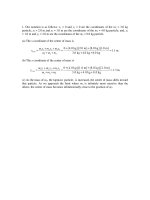
(a) If rear-wheel brakes fail to operate:
ΣM A = Σ ( M A )eff : N B (12 ft ) − W ( 5 ft ) = ma ( 4 ft )
NB =
5
1W
W +
a
12
3 g
ΣFx = Σ ( Fx )eff : FB = ma , µ k N B =
W
a
g
5
1W W
0.699 W +
a =
a
3 g
g
12
5
0.699 32.2 ft/s 2
12
a =
a = 12.227 ft/s2
1 − 0.233
Uniformly accelerated motion
(
v 2 = v02 + 2ax
)
(
) (
)
0 = 30 ft/s 2 − 2 12.227 ft/s2 x
x = 36.8 ft !
(b) If front-wheel brakes fail to operate:
ΣM B = Σ ( M B )eff : W ( 7 ft ) − N A (12 ft ) = ma ( 4 ft )
NA =
7
1W
W −
a
12
3 g
continued
Vector Mechanics for Engineers: Statics and Dynamics, 8/e, Ferdinand P. Beer, E. Russell Johnston, Jr.,
Elliot R. Eisenberg, William E. Clausen, David Mazurek, Phillip J. Cornwell
© 2007 The McGraw-Hill Companies.
COSMOS: Complete Online Solutions Manual Organization System
ΣFx = Σ ( Fx )eff : FA = ma , µ k N A =
W
a
g
7
1W W
0.699 W −
a =
a
3 g
g
12
7
0.699 32.2 ft/s 2
12
a =
1 + 0.233
(
)
a = 10.648 ft/s 2
Uniformly accelerated motion
v 2 = v02 + 2ax
(
) (
)
0 = 30 ft/s 2 − 2 10.648 ft/s 2 x
x = 42.3 ft !
Vector Mechanics for Engineers: Statics and Dynamics, 8/e, Ferdinand P. Beer, E. Russell Johnston, Jr.,
Elliot R. Eisenberg, William E. Clausen, David Mazurek, Phillip J. Cornwell
© 2007 The McGraw-Hill Companies.
COSMOS: Complete Online Solutions Manual Organization System
Chapter 16, Solution 6.
(a) Four-wheel drive:
ΣFy = 0: N A + N B − W = 0
Thus:
N A + N B = W = mg
FA + FB = µk N A + µ k N B = µ k ( N A + N B ) = µ kW = 0.80mg
ΣFx = Σ ( Fx )eff : FA + FB = ma
0.80mg = ma
(
)
a = 0.80 g = 0.80 9.81 m/s 2 = 7.848 m/s 2
a = 7.85 m/s 2 !
(b) Rear-wheel drive:
ΣM B = Σ ( M B )eff :
(1 m )W − (1.5 m ) N A
= − ( 0.5 m ) ma
N A = 0.4W + 0.2ma
Thus:
FA = µk N B = 0.80 ( 0.4W + 0.2ma ) = 0.32mg + 0.16ma
ΣFx = Σ ( Fx )eff : FA = ma
0.32mg + 0.16ma = ma
0.32 g = 0.84a
a =
(
)
0.32
9.81 m/s 2 = 3.7371 m/s 2
0.84
or a = 3.74 m/s 2 !
continued
Vector Mechanics for Engineers: Statics and Dynamics, 8/e, Ferdinand P. Beer, E. Russell Johnston, Jr.,
Elliot R. Eisenberg, William E. Clausen, David Mazurek, Phillip J. Cornwell
© 2007 The McGraw-Hill Companies.
COSMOS: Complete Online Solutions Manual Organization System
(c) Front-wheel drive:
ΣM A = Σ ( M A )eff :
( 2.5 m ) N B − (1.5 m )W
= − ( 0.5 m ) ma
N B = 0.6W − 0.2ma
Thus:
FB = µk N B = 0.80 ( 0.6W − 0.2ma ) = 0.48mg − 0.16ma
ΣFx = Σ ( Fx )eff : FB = ma
0.48mg − 0.16ma = ma
0.48g = 1.16a
a =
(
)
0.48
9.81 m/s 2 = 4.0593 m/s 2
1.16
or a = 4.06 m/s 2
Vector Mechanics for Engineers: Statics and Dynamics, 8/e, Ferdinand P. Beer, E. Russell Johnston, Jr.,
Elliot R. Eisenberg, William E. Clausen, David Mazurek, Phillip J. Cornwell
© 2007 The McGraw-Hill Companies.
!
COSMOS: Complete Online Solutions Manual Organization System
Chapter 16, Solution 7.
(a) Sliding impends:
ΣFy = Σ ( Fx )eff : F = ma cos 30°
( )eff :
ΣFy = Σ Fy
N − mg = ma sin 30°
N = m ( g + a sin 30° )
μs =
F
;
N
0.25 =
ma cos 30°
;
m ( g + a sin 30° )
g + a sin 30° = 3.3333a cos 30°
g = 2.3867a
a = 0.419g
30° !
(b) Tipping impends:
⎛h⎞
⎛d ⎞
ΣM G = Σ ( M G )eff : F ⎜ ⎟ − N ⎜ ⎟ = 0
2
⎝ ⎠
⎝2⎠
F
d
=
N
h
μ =
Vector Mechanics for Engineers: Statics and Dynamics, 8/e, Ferdinand P. Beer, E. Russell Johnston, Jr.,
Elliot R. Eisenberg, William E. Clausen, David Mazurek, Phillip J. Cornwell
© 2007 The McGraw-Hill Companies.
F
;
N
0.3 =
d
;
h
h
= 3.33 !
d
COSMOS: Complete Online Solutions Manual Organization System
Chapter 16, Solution 8.
(a) Sliding impends:
ΣFx = Σ ( Fx )eff : F = ma cos 30°
( )eff :
ΣFy = Σ Fy
N − mg = −ma sin 30°
N = m ( g − a sin 30° )
μs =
F
;
N
0.3 =
ma cos 30°
m ( g − a sin 30° )
g − a sin 30° = 3.3333a cos 30°
1
a
=
= 0.29527
g
3.3333cos 30° + sin 30°
a = 0.295
!
(b) Tipping impends:
ΣM G = Σ ( M G )eff
⎛h⎞
⎛d⎞
F ⎜ ⎟ = W ⎜ ⎟;
⎝2⎠
⎝2⎠
F
d
=
N
h
μ =
Vector Mechanics for Engineers: Statics and Dynamics, 8/e, Ferdinand P. Beer, E. Russell Johnston, Jr.,
Elliot R. Eisenberg, William E. Clausen, David Mazurek, Phillip J. Cornwell
© 2007 The McGraw-Hill Companies.
F
;
N
0.30 =
d
;
h
h
= 3.33 !
d
COSMOS: Complete Online Solutions Manual Organization System
Chapter 16, Solution 9.
(a) Acceleration
ΣFx = Σ ( Fx )eff :
25 lb = ma
25 lb =
50 lb
a
32 ft/s 2
a = 16.10 ft/s 2 !
(b) For tipping to impend
;
A=0
ΣM B = Σ ( M B )eff :
( 25 lb ) h − ( 50 lb )(12 in.) = ma ( 36 in.)
For tipping to impend
;
B=0
ΣM A = Σ ( M A )eff :
( 25 lb ) h + ( 50 lb )(12 in.) = ma ( 36 )
or
h = 12 in.
cabinet will not tip for 12 in. ≤ h ≤ 60 in. !
Vector Mechanics for Engineers: Statics and Dynamics, 8/e, Ferdinand P. Beer, E. Russell Johnston, Jr.,
Elliot R. Eisenberg, William E. Clausen, David Mazurek, Phillip J. Cornwell
© 2007 The McGraw-Hill Companies.
COSMOS: Complete Online Solutions Manual Organization System
Chapter 16, Solution 10.
ΣFy = 0
(a) Acceleration
N A + NB − W = 0
N A + N B = 50 lb
But F = μ N , Thus
FA + FB = μ s ( 50 lb ) ,
μ s = 0.25
ΣFx = Σ ( Fx )eff :
25 lb − ( FA + FB ) = ma
⎛ 50 lb ⎞
25 lb − ⎣⎡( 0.25)( 50 lb ) ⎦⎤ = ⎜
a
2⎟
⎝ 32.2 ft/s ⎠
a = 8.05 ft/s 2
(b) Tipping
For tipping to impend
: NA = 0
ΣM B = Σ ( M B )eff :
( 25 lb ) h − ( 50 lb )(12 in.) =
(
)
50 lb
8.05 ft/s 2 ( 36 in.)
32.2 ft/s 2
h = 42 in.
For tipping to impend
:
NB = 0
ΣM A = Σ ( M A )eff :
( 25 lb ) + ( 50 lb )(12 in.) =
(
)
50 lb
8.05 ft/s 2 ( 36 in.)
32.2 ft/s 2
h = −6 in.
impossible
cabinet will not tip if h ≤ 42 in. !
Vector Mechanics for Engineers: Statics and Dynamics, 8/e, Ferdinand P. Beer, E. Russell Johnston, Jr.,
Elliot R. Eisenberg, William E. Clausen, David Mazurek, Phillip J. Cornwell
© 2007 The McGraw-Hill Companies.
COSMOS: Complete Online Solutions Manual Organization System
Chapter 16, Solution 11.
ΣM G = 0 ⇒ FA = 0
ΣF⊥ BG = ( mg )( sin 30° ) = ma
a=
g
2
or
a = 16.1 ft/s 2
∑ F& BG = FB − (16 lb )( cos 30° ) = 0
FB = 13.856 lb
(a)
a = 16.10 ft/s 2
(b)
FA = 0, FB = 13.86 lb compression W
Vector Mechanics for Engineers: Statics and Dynamics, 8/e, Ferdinand P. Beer, E. Russell Johnston, Jr.,
Elliot R. Eisenberg, William E. Clausen, David Mazurek, Phillip J. Cornwell
© 2007 The McGraw-Hill Companies.
30°W
COSMOS: Complete Online Solutions Manual Organization System
(c) Front-wheel drive:
ΣM A = Σ ( M A )eff :
( 2.5 m ) N B − (1.5 m )W
= − ( 0.5 m ) ma
N B = 0.6W − 0.2ma
Thus:
FB = μ k N B = 0.80 ( 0.6W − 0.2ma ) = 0.48mg − 0.16ma
ΣFx = Σ ( Fx )eff : FB = ma
0.48mg − 0.16ma = ma
0.48 g = 1.16a
a =
(
)
0.48
9.81 m/s 2 = 4.0593 m/s 2
1.16
or a = 4.06 m/s 2
Vector Mechanics for Engineers: Statics and Dynamics, 8/e, Ferdinand P. Beer, E. Russell Johnston, Jr.,
Elliot R. Eisenberg, William E. Clausen, David Mazurek, Phillip J. Cornwell
© 2007 The McGraw-Hill Companies.
!
COSMOS: Complete Online Solutions Manual Organization System
Chapter 16, Solution 12.
Analysis of linkage
Since members ACE and DCB are of negligible
mass, their effective forces may also be
neglected and the methods of statics may be
applied to their analysis.
Free body: Entire linkage:
ΣM D = 0:
(B
(B
y
y
)
− E ) cos 30°− B
− E ( 30 sin 30°) − Bx ( 30 sin 30°) = 0
x
sin 30° = 0
(1)
Free body: member ACE
ΣM C = 0:
A (15 cos30°) − E (15 cos30°) = 0 ;
E=A
carrying into eq. (1):
(B
y
)
− A cos30°− Bx sin 30° = 0
Equations of motion for member AB
Vector Mechanics for Engineers: Statics and Dynamics, 8/e, Ferdinand P. Beer, E. Russell Johnston, Jr.,
Elliot R. Eisenberg, William E. Clausen, David Mazurek, Phillip J. Cornwell
© 2007 The McGraw-Hill Companies.
(2)
COSMOS: Complete Online Solutions Manual Organization System
(a)
+
60° ΣFt − ∑ ( Ft ) eff :
(B
y
)
− A cos 30°− Bx sin 30° + W cos 30° = ma
Recalling equation (2), we have,
W cos 30° = ma
(
a =
W
cos 30° = g cos 30°
m
)
a = 32.2 ft/s 2 cos30°
(b)
a = 27.9 ft/s 2
60° !
ΣM B = ∑ ( M B )eff :
W ( 7.5 in.) − A ( 30 in.) cos 30° = ( ma sin 60°)( 7.5 in.) − ( ma cos 60°)( 2.5 in.)
But ma = W cos 30° As found above.
Thus:
7.5 W − 30 A cos 30° = W cos 30° ( 7.5 sin 60° − 2.5 cos 60° )
1
1
1
cos 60° = 0.11384 W
A =W
− sin 60° +
12
4 cos 30° 4
Recalling that W = 20 lb
A = 0.11384 ( 20 lb ) = 2.2768 lb
A = 2.28 lb !
Vector Mechanics for Engineers: Statics and Dynamics, 8/e, Ferdinand P. Beer, E. Russell Johnston, Jr.,
Elliot R. Eisenberg, William E. Clausen, David Mazurek, Phillip J. Cornwell
© 2007 The McGraw-Hill Companies.
COSMOS: Complete Online Solutions Manual Organization System
Chapter 16, Solution 13.
Bar AC
ΣM C = 0 ⇒ 6 N ⋅ m − R1 ( 0.45 m ) = 0
R1 =
6 N ⋅ m 40
N
=
0.45 m
3
Bar AB
ΣFx =
(a)
40
N − ( 4 )( 9.81) sin 30° = − 4 a
3
a = 1.5717 m/s 2
or a = 1.572 m/s 2
(b)
30° !
∑ M A = ( ∑ M A )eff :
∑ M A = ( 39.24 N )( 0.3 m ) − TEB ( cos 30° )( 0.6 m ) = ma ( sin 30° )( 0.3 m )
TAB =
− ( 4 )(1.5717 )( 0.15 ) + 11.772
= 20.841 N
( 0.866 )( 0.6 )
or TAB = 20.8 N !
Vector Mechanics for Engineers: Statics and Dynamics, 8/e, Ferdinand P. Beer, E. Russell Johnston, Jr.,
Elliot R. Eisenberg, William E. Clausen, David Mazurek, Phillip J. Cornwell
© 2007 The McGraw-Hill Companies.
COSMOS: Complete Online Solutions Manual Organization System
Chapter 16, Solution 14.
Bar AC
ΣM C = 0
0 = M − R1 ( 0.45 ) ,
ΣFx =
so R1 =
M
0.45
)
M = 1.629 N ⋅ m !
(a)
(b)
(
M
− ( 39.24 N )( sin 30° ) = − ( 4 kg ) 4 m/s 2
0.45 m
ΣM A = ( 39.24 N )( 0.3 m ) − TEB ( cos 30° )( 0.6 m ) = ma ( sin 30° )( 0.3 m )
TEB = 18.036 N
or TEB = 18.04 N !
Vector Mechanics for Engineers: Statics and Dynamics, 8/e, Ferdinand P. Beer, E. Russell Johnston, Jr.,
Elliot R. Eisenberg, William E. Clausen, David Mazurek, Phillip J. Cornwell
© 2007 The McGraw-Hill Companies.
COSMOS: Complete Online Solutions Manual Organization System
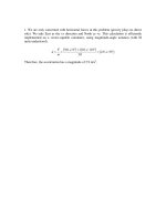
Chapter 16, Solution 15.
We will need the acceleration of the center of gravity of the bar and since it is translating let’s find the
acceleration of point B.
ω = 180 rpm = 18.85 rad/s
Since ω is constant
aB = aBn = rω 2 = ( 0.2 m )(18.85 rad/s )
2
= 71.061 m/s 2
Since AB is translating
aG = aB = 71.061 m/s 2 60°
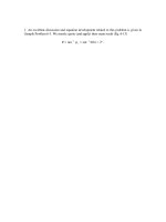
Apply Newton’s second law to the system = Bar BC
ΣM B = ( ΣM B )eff ⇒ C y ( 0.75 ) − mg ( 0.375 ) = − maG sin 60° ( 0.375 )
C y = 0.5 mg − maG sin 60° ( 0.5 )
= 0.5 ( 7.5 )( 9.81) − 7.5 ( 71.061) sin 60° ( 0.5 )
= −193.99 N
C y = 194.0 N
(
ΣFy = ΣFy
!
)eff ⇒ By − mg + C y = − maG sin 60°
By = mg − C y − maG sin 60° = 7.5 ( 9.81) + 193.99 − 7.5 ( 71.061) sin 60°
= −193.99 N
By = 194.0 N !
Vector Mechanics for Engineers: Statics and Dynamics, 8/e, Ferdinand P. Beer, E. Russell Johnston, Jr.,
Elliot R. Eisenberg, William E. Clausen, David Mazurek, Phillip J. Cornwell
© 2007 The McGraw-Hill Companies.
COSMOS: Complete Online Solutions Manual Organization System
Chapter 16, Solution 16.
∑ M G = 0 = 200 ( 0.6 )( 0.866 ) − 300 ( 0.6 )( 0.866 ) + P ( 0.6 )( 0.5)
P = 173.2 N
(a)
!
∑ Fy = 300 − 5 ( 9.81) + 200 = 5 ( 0.4 )ω 2
ω = 15.02 rad/s !
(b)
∑ Fx = P = 5 ( 0.4 )α = 173.2
(c)
Vector Mechanics for Engineers: Statics and Dynamics, 8/e, Ferdinand P. Beer, E. Russell Johnston, Jr.,
Elliot R. Eisenberg, William E. Clausen, David Mazurek, Phillip J. Cornwell
© 2007 The McGraw-Hill Companies.
α = 86.6 rad/s 2
!
COSMOS: Complete Online Solutions Manual Organization System
Chapter 16, Solution 17.
Bar AB
Free body diagram
Kinetic diagram
an = 0; Released from rest
∑ Fx = ( ∑ Fx )eff
8 u g
−V =
cos 30 °
32.2 1.5 2
− V = 2.3094 u
− V = 2.3094 u
At u = 1.5 ft
V = − 3.464 lb;
u
+ ∑ M p = M = mat 2
8 u g
u
M =
cos 30°
32.2 1.5 2
2
M = 1.1547 u 2
At
u = 1.5 ft;
Shear
M = 2.598 ft ⋅ lb
Moment
"
Vector Mechanics for Engineers: Statics and Dynamics, 8/e, Ferdinand P. Beer, E. Russell Johnston, Jr.,
Elliot R. Eisenberg, William E. Clausen, David Mazurek, Phillip J. Cornwell
© 2007 The McGraw-Hill Companies.
COSMOS: Complete Online Solutions Manual Organization System
Bar BE
8 u
u
mg =
g = 8
32.2 1.5
1.5
8 u g
m ax =
cos 30° = 2.3094 u
32.2 1.5 2
∑ Fx = ( ∑ Fx )eff
u
− V + 8
cos 30 ° = 2.3094 u
1.5
V = 2.3094 u
+
∑ M p = M + 8
u
u
u
cos30° = 2.3094 u
1.5
2
2
M = −1.1547 u 2
Shear
Moment
"
"
Vector Mechanics for Engineers: Statics and Dynamics, 8/e, Ferdinand P. Beer, E. Russell Johnston, Jr.,
Elliot R. Eisenberg, William E. Clausen, David Mazurek, Phillip J. Cornwell
© 2007 The McGraw-Hill Companies.
COSMOS: Complete Online Solutions Manual Organization System
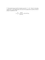
Chapter 16, Solution 18.
From Problem 16.15
aG = 71.061 m/s 2 60°
a y = 61.541 m/s 2
Distributed mass per unit length =
m 7.5 kg
=
= 10 kg m
L 0.75 m
(
)
Distributed weight per unit length = (10 kg/m ) 9.81 m/s 2 = 98.1 N/m
(
)
Vertical component of effective forces = ma y = (10 kg/m ) 61.541 m/s 2 = 615.41 N/m
∑ Fy = ( ∑ Fy )eff : By + C y + ( 98.1)( 0.75 ) = ( 0.75 )( 615.41 N/m )
B y + C y = 387.98
From symmetry By = C y = 194.0 N (Same as what we got for Prob. 16.15)
Max value of bending moment occurs at G where V = 0
M
max
= Area under V – Diagram from B to G
=
1
(194.0 N )( 0.375 m )
2
VB = −194 N !
M
Vector Mechanics for Engineers: Statics and Dynamics, 8/e, Ferdinand P. Beer, E. Russell Johnston, Jr.,
Elliot R. Eisenberg, William E. Clausen, David Mazurek, Phillip J. Cornwell
© 2007 The McGraw-Hill Companies.
max
= 36.4 N ⋅ m !
COSMOS: Complete Online Solutions Manual Organization System
Chapter 16, Solution 19.
Since slab is in translation, each particle has same acceleration as G, namely a. The effective forces consist of
( Δmi ) a.
The sum of these vectors is:
Σ ( Δmi ) a = ( ΣΔmi ) a
or since ΣΔmi = m,
Σ ( Δmi ) a = m a
The sum of the moments about G is:
Σri′ × ( Δmi ) a = ( ΣΔmi ri′) × a
(1)
But, ΣΔmi ri′ = mr ′ = 0, because G is the mass center. It follows that the right-hand member of Eq. (1) is zero.
Thus, the moment about G of ma must also be zero, which means that its line of action passes through G and
that it may be attached at G.
Vector Mechanics for Engineers: Statics and Dynamics, 8/e, Ferdinand P. Beer, E. Russell Johnston, Jr.,
Elliot R. Eisenberg, William E. Clausen, David Mazurek, Phillip J. Cornwell
© 2007 The McGraw-Hill Companies.
COSMOS: Complete Online Solutions Manual Organization System
Chapter 16, Solution 20.
For centroidal rotation: ai = ( ai )t + ( ai )n = α × ri′ − ω 2ri′
( Δmi ) ai
Effective forces are:
= ( Δmi )( α × ri ) − ( Δmi ) ω 2ri′( Δmi )(α × ri )
Σ ( Δmi ) ai = Σ ( Δmi )( α × ri′) − Σ ( Δmi ) ω 2ri′
= α × Σ ( Δmi ) ri′ − ω 2Σ ( Δmi ) ri′
Since G is the mass center,
Σ ( Δmi ) ri′ = 0
∴ effective forces reduce to a couple, summing moments about G
(
)
Σ ( r1′ × Δmiai ) = Σ ⎡ri′ × ( Δmi ) α × ri′ ⎤ − Σri′ × ( Δmi ) ω 2ri′
⎣⎢
⎦⎥
ri′ × ( Δmi ) ω 2ri′ = ω 2 ( Δmi )( ri′ × ri′) = 0
But,
ri′ × ( Δmi )( α × ri′) = ( Δmi ) r1′2α
and,
Thus,
Σ ( ri′ × Δmiai ) = Σ ( Δmi ) r12α = ⎡⎣Σ ( Δmi ) r′i2⎤⎦ α
Since
Σ ( Δm ) r ′i 2 = I ,
the moment of the couple is I α
Vector Mechanics for Engineers: Statics and Dynamics, 8/e, Ferdinand P. Beer, E. Russell Johnston, Jr.,
Elliot R. Eisenberg, William E. Clausen, David Mazurek, Phillip J. Cornwell
© 2007 The McGraw-Hill Companies.